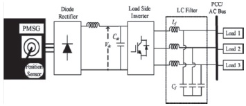
Figure 1. Standalone Wind Energy System
This paper deals with a wind energy conversion system connected with grid. In this system rotor side and grid side converters are used to cope with reactive powers generated and to get the balanced output at the load side. A very effective control technique has been developed based on pulse width modulation to make the line voltages at the point of common coupling. Various filters have been used in this system and according to different filter parameters and design, the total harmonic distortion (THD) has been compared and calculated accordingly.
The consumption of fossil fuel increases day by day as there is a need to generate more and more energy for the increasing domestic and commercial use. The use of such fuels affect the environment badly. To overcome all these situation the Ministry of New and Renewable Energy (MNRE) has proposed many incentives programs to promote renewable source of energy for generation of electricity as far as possible so as to provide green and clean energy. Wind energy and solar energy plays a vital role in renewable energy generation.
In this paper we discuss a wind energy conversion system connected with grid with some standard parameters. There are two methods such as isolated standalone system and grid connected wind energy conversion system.
In wind energy application, variable speed wind turbines have much better performance due to its maximum power point tracking system (MPPT). Nowadays, doubly fed induction generator are widely used in a variable speed wind turbine but the main drawback is the requirement of gear box to match turbine and rotor speed. The gear box many times suffers and requires regular maintenance making the system unreliable (Polinder et al., 2006). The reliability of variable speed wind turbine can be improved by using direct drive permanent magnet synchronous generator (Bhende et al., 2011).
The output of wind turbine is not suitable for use as its amplitude and frequency are not stable due to variation in wind speed. A constant DC voltage is required for direct use or to convert into AC via inverter. Normally two converters are used in this system, rotor side converter and grid side converter. In the system, for rotor side converter we have used three phase diode bridge rectifier and grid side IGBT/diode, and three phase converter. Different control technique has been used for the signal input to the gate of IGBT converter and the output signal passes through various filters before supplying to any kind of load or grid. The standalone wind energy system is shown in Figure 1.
Figure 1. Standalone Wind Energy System
Various analysis has been done in this research regarding different filters used and total harmonic distortion calculated in various conditions.
Different future scopes can be generated regarding power quality improvement by using FACTS devices such as STATCOM, SVC or by any other method by using this analysis.
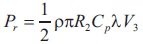
According to aerodynamics, the power of wind turbine can be expressed as,
When the rotor speed is adjusted to maintain its optimal value, the maximum power can be gained as,
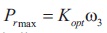
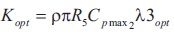
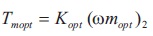
we can get the maximum output power at various wind speed that varies according to wind speed from the optimum power curve shown by the wind turbine characteristics (Ackermann, 2005; Nath & Rana,2011). The wind turbine parameters is given in Table 1.
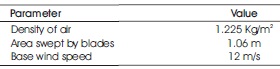
Table 1.Wind Turbine Parameters
WECS is represented with the two mass drive train model. The differential equation governing its mechanical dynamics are as follows,
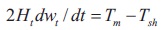
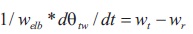
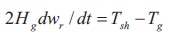
where Ht is the inertia constant of turbine and Hg is the inertia constant of PMSG where, θtw is the shaft twist angle, wt is the angular speed of wind turbine in pu, wt is the rotor speed of PMSG in pu, welb is the electrical base speed and the shaft torque is Tsh.
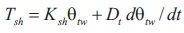
where Ksh is shaft stiffness and Dt is the damping coefficient.
For converting mechanical energy obtained from the wind into electricity, PMSG system has been considered. The dynamic model of the PMSG is created from the two phase synchronous reference frame, in which the q-axis is 90° ahead of the d-axis with respect to the direction of rotation. By utilizing a phase locked loop (PLL) the synchronization between the d-q rotating reference frame and the abcthree phase frame is maintained (Upadhyay et al., 2013). Figure 2 shows the d-q reference frame for a salient-pole synchronous machine (which is the same reference as the one used in a PMSG), where the mechanical angle, which is the angle between the rotor d-axis and the stator axis.
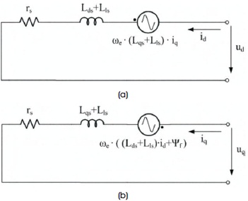
Figure 2. Equivalent Circuit of PMSG in Synchronous Frame (a) d-axis Equivalent Circuit (b) q-axis Equivalent Circuit
For representing mathematical model of PMSG, the state equations are given.
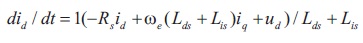
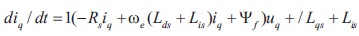
where subscript d and q classify the physical quantities that have been changed into the d, q synchronous rotating reference frame, R is the stator resistance (Ω), Ld and Lq are the inductances (H) of the generator on the d and q axis, respectively, ψt is the permanently magnetic flux (wb) and the electrical rotating speed (rad/s) of the generator is given by ωe.
ωe =p ωm
Where p represents the number of pole pairs of the generator and ωm is the mechanical angular speed. Mathematical equation is needed in order to execute the mathematical model of PMSG and it is given by the electromagnetic torque equation. The PMSG parameters are given in Table 2.
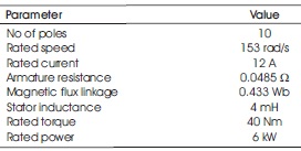
Table 2. PMSG Parameters
In this proposed wind energy conversion system the output AC voltage is controlled through the frequency and amplitude. The inverter control system is shown in Figure 3 and their subsystems is shown in Figure 4 and 5. The reactive power exchange with the line depends on the phase and amplitude of terminal voltage at terminals of grid side converter (Chinchilla et al., 2006; Verma et al., 2014).
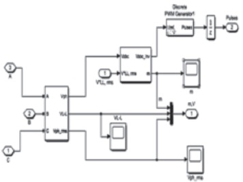
Figure 3. Inverter Control System
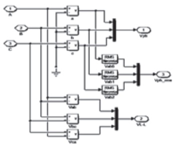
Figure 4. Subsystem of Control System
The transmission lines has inductive as well as capacitive loads and if there is a fault, unbalancing of load occurs affecting the output voltage. The objective of controlling grid side converter is to keep constant DC link voltage under change in generated active power. The currents are not balanced in all the phases, so filters also cause unequal voltages.
All the three phase voltages are processed for rms and discrete values and set accordingly so that we can input the desired values to our next subsystem of the control system.
As Figure 5 shows the output, output of PI controller is multiplied with the sine wave and we get the Vabc inverter and after that this signal is processed from PWM generator to get the PWM pulse of load side inverter.
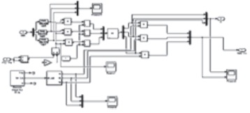
Figure 5. Control System Subsystem Output
In order to get the better sinusoidal voltages the resonance frequency of the filter has to be well below the lowest harmonic frequency of inverter voltage resulting from pulse width modulation. The resonant frequency is determined by the product of L and C (Steinke, 1999).
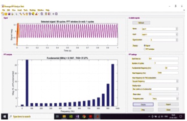
Figure 6. FFT analysis of first case THD 38%
According to the cost and weight, we can choose the values of inductor and capacitor.
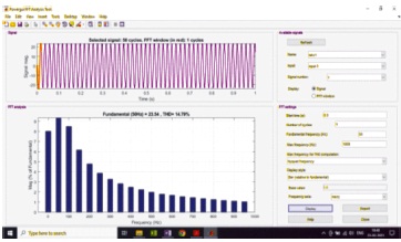
Figure 7. FFT Analysis of Second Case THD 14%
In the first case, we have taken a simple LC filter with values of inductance of 1milli henry and 1 micro farad and current harmonic distortion is evaluated. The FTT analysis of first case and second case is shown in Figure 6 and 7 respectively. From FFT analysis we can see that the THD percentage is around 38% and in the very next case if we take only inductor filter of 1.2 mH and ignoring the value of capacitance, then the THD values are about 14% in the currents of the phases.
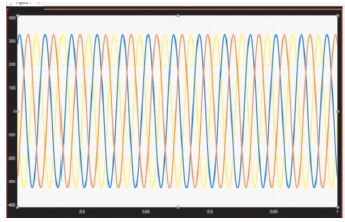
Figure 8. Voltage Waveform
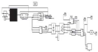
Figure 9. Simulink Model
Voltage waveform is sinusoidal as shown in Figure 8. The Simulink model is shown in Figure 9.
A wind energy conversion system has been designed and the whole system is connected to the grid with the pitch control system in the turbine. The synchronous generator is used as it has various advantages and the three phase diode bridge rectifier has been used in the rotor side converter. After going through the DC link capacitor an IGBT/diode inverter has been designed with the gate pulse generated by PWM generator and after passing through various filters we have the output voltage in the grid side. By using two different types of filters, the THD value from the FFT analysis has been discovered; one is 37 and another is 14 percent. Our aim is to analyze and reduce harmonics from the output as much as we can and from the optimization of the system, it is achieved.
Future scope is that various FACTS devices can be used for power quality improvements like STATCOM and SVC for harmonic reduction in the outputs.