Figure 1. Basic Configuration of UPFC
This paper presents the use of Unified Power Flow Controller (UPFC) for mitigation of voltage sag and swell in power system. The power quality issues such as voltage fluctuations, power frequency variations, harmonics, voltage sag and swell, noise, etc., causes low power issue, low potency, enlarged losses in transmission and distribution lines, failure of electrical equipment and interference weakness with communication system. It is important to mitigate these reactive current parts and harmonic, which is done by Active Power filters. Also, voltage in all buses may not be same due to changes in load. To resolve the above issues UPFC device is used in this work. UPFC is one of the types of FACTS devices which are very useful in voltage compensation. UPFC is a three-phase device, with a combination of series and shunt active power filter with common DC link. It is employed to eliminate voltage swell and sag compensation in power system, current harmonics, compensate reactive power etc. In this paper, MATLAB (SIMULINK) based UPFC simulation model is developed and analyzed for voltage swell and sag compensation in distribution system.
The electricity find vital role in our day to day life as it has become a part of our life and we cannot think of living without electricity. One of the key factors for the drastic improvement in our life style is electricity. Every work we do is dependent on electricity. From, cooking to cleaning, work to sleep, in industries, commercial use, entertainment etc., everything needs electricity. The power necessity is growing daily. Energy is important for the growth of the whole nation and the world and it is the economic driver. The decline in power supply and increase in energy demand leads to the power crisis. The energy demand has major effect in growth of a nation. Energy crisis put an end to the establishment of new industrial units, and may lead to the closure of existing industries in a nation. The issues directly resulting in unemployment and recessions of a factor, which leads to increasing poverty. Hence, it is very important to maintain the energy demand and energy generation to go hand-in-hand.
The UPFC is a flexible device and it can, not only deliver additional flexibility by combining some of the functions of the controllers, it also execute the functions of the static synchronous compensator (STATCOM), thyristor switched capacitor (TSC), thyristor-controlled reactor (TCR), and the phase angle regulator (Hingorani, 1988). The UPFC performs the operation of controlling the real and reactive power by varying series voltage magnitude and phase angle. Further it controls real and reactive power in particular path, limit the loading of transmission line close to its thermal limits and further improve the transient and small signal stability of the power system. This work mainly focuses on resolving voltage instability. The UPFC (unified power flow controller) eliminates the voltage sag and swell leading to voltage stability improvement. In this paper, MATLAB (SIMULINK) based UPFC simulation model is developed and analyzed for voltage swell and sag compensation in distribution system.
In Singh et al. (1999), authors reviewed the active filters for power quality improvement. In Enslin (1998), unified approach to power quality mitigation is proposed. The concepts of UPFC for AC transmission system were discussed (Gyugi, 1992; Papic et al., 1997). In Smith et al. (1997), dynamic modeling of a UPFC is done. In Padiyar (1998), control design and simulation of UPFC is done. In Jianjun (2002) the principle, control and application of unified power quality conditioner is discussed. In Kannan et al. (2004), real & reactive power coordination for UPFC is discussed. Authors discussed about dynamic voltage restorer for voltage sag mitigation in oil & gas applications in Chesteen et al. (2015). In Ahmed et al. (2020), the low switching frequency modulation of 3x3 matrix converters in UPFC application using differential evaluation method were discussed.
According to IEEE standard 1159, sag is defined as a decrease in rms voltage to 0.1-0.9 pu at the network fundamental frequency with duration from 0.5 cycles to one minute.
Voltage swell is defined by IEEE 1159 as increase in the rms voltage level to 1.1 -1.8 pu in rms voltage at the network fundamental frequency with duration from 0.5 cycles to one minute.
The voltage for the purpose of common coupling might or might not read the counting of opposite nonlinear in a proper way. These nonlinearity causes' voltage sag and voltage swell condition throughout the ON and OFF operation. Therefore, UPFC is used as a guard to sensitive loads from all kinds of disruptions.
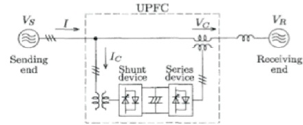
The Figure 1 displays the basic configuration of UPFC, which is installed between the receiving-end and sending-end. The device comprises of a union of a series and a shunt device, the DC terminals of which are linked to a general DC link capacitor.
Figure 1. Basic Configuration of UPFC
The Figure 2 shows the circuit diagram of UPFC. UPFC contains two converters, one of which is serially connected to the conductor through a series inserted electrical device and the other one connected in shunt to the conductor through a shunt electrical device. The DC ends of the two converters is linked along the DC electrical device. To insert voltage magnitude and phase, the series device management is used, to regulate the active and reactive power flows on the conductor the series device can exchange reactive and active power.
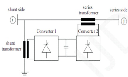
Figure 2. Circuit Diagram of UPFC
The main purpose of using UPFC is that, resolving the transmission line compensation issues and mistreatments that provide fixed flexibility which cannot be obtained by thyristor-controlled controllers. The unit forms two parts of UPFC, one as a general UPFC for power distribution systems and industrial power systems, the other UPFC for treating voltage flicker/imbalance, sensitive load (load fluctuations), caused by electrical power consumers. To maintain desired voltage magnitude at load bus, the UPFC controller is used. Therefore, the series active power filter is used to inject voltage which is equal to the difference between the running voltage and the reference load voltage. The DC link voltage at constant value is maintained by shunt active power filter. Additionally, the shunt filter offers the voltampere required by the load, such that the input power issue are unity and only the basic active power are equipped by the source (Sahu et al., 2014).
The supply voltage is denoted by and load voltage by VL. The supply and load currents are denoted by IS and IL respectively.
Vsr - voltage injected by series power filter.
ISh - current injected by shunt power filter.
VL - load reference phase
CosϕL - power factor of the load


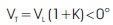
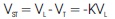
where, fluctuation of source voltage is represented by K and is defined as

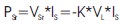
Active power filter voltage injection is equal to
Assuming, the unified power quality conditioner has no loss and the active power demanded by the load is compensated by active power input at point of common coupling. The UPFC delivers almost unity preferably source current, hence, the active power at PCC (Point of Common Coupling) is equal to load power and can be stated by the succeeding equations

From, the above equation, the source current IS depends on the factor K. Since ϕL and IL are load characteristics and are constant for a specific type of load. The absorption of complex power by the series active power filter can be expressed as the following


Since, unity power factor is maintained by unified power quality conditioner, ϕS=0

The absorption of complex power by the shunt active power filter can be expressed as,

The power transmission capability of long transmission lines is commonly limited by their thermal capacity. With UPFC, using the present transmission line at its extreme thermal ability is possible.
Based on synchronous rotating coordinate system, the control strategies of UPFC were developed by the conventional amplitude and phase control. The construction of the UPFC unit was also from the traditional linear PI (proportional integration) or PID (proportional integration differentiation) to fuzzy control, decoupling control, neural network which are related to decoupling control, adaptive theory, cross-coupling and coordinated control.
3.1 Shunt Converter Control The shunt branch of the UPFC controls the bus voltage, the shunt reactive power and the DC link capacitor voltage. In this method, the shunt converter voltage is divided into two components one in phase with the UPFC bus voltage and the other in the quadrature. By using de-coupled control system, UPFC bus voltage and the DC link capacitor voltage can be controlled. The Figure 3 shows the configuration of de-coupled control system for the shunt converter. The DC link capacitor voltage Vdc is controlled by the D-axis and the bus voltage Vupfcbus or shunt reactive power is controlled by Q-axis unit.
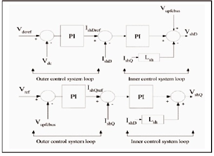
Figure 3. Basic Configuration of UPFC
The shunt converter control system is designed based on the linear control system technique and it comprises of outer loop control unit that sets the reference for the inner control system loop.
The series control unit provides concurrent control of real and reactive power flow in the transmission line. For the above process to take place, the voltage injected in the series converter is divided in to two components. One component is in phase with the UPFC bus voltage and other with quadrature. The transmission line real power flow is controlled by quadrature component of the series injected voltage and is similar to the strategy of the phase shifter. The reactive power flow of transmission line is controlled by the in-phase component and the process is similar to the strategy of the tap changer.
The Figure 4 shows the diagram of the complete series converter control unit.
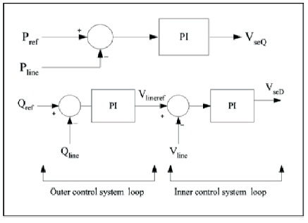
Figure 4. Real and Reactive Power Flow Control of Series Converter System
Figure 5 shows the proposed controller UPFC. It is a combination of shunt converter and series converter connected via a common DC link capacitor. UPFC utilizes a set of three-phase controllable bridges to generate current that is added into a transmission line using a series transformer. The device controls active and reactive power flows in a transmission line. The simulation of complete generating system using UPFC (unified power flow controller), to reduce the voltage sag and swell resulting in improvised system efficiency. The parameters used for simulation are given in Table 1.
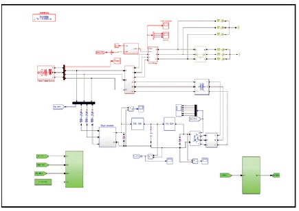
Figure 5. Simulation Model of Shunt and Series Converter with System
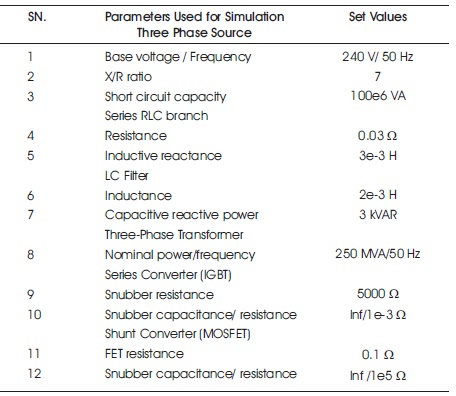
Table 1. FL Controller Rules
The Figure 6 represents block diagram of the shunt converter controller. The conventional control strategy for this inverter concerns with the control of AC-bus and DC-link voltage. The dual control objectives are met by generating appropriate current reference (for d-axis and q-axis) and then, by regulating those currents. PI controllers are conventionally employed for both the tasks while attempting to decouple the d-axis and q-axis current regulators.
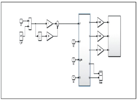
Figure 6. Block Diagram of Shunt Converter Controller
In figure 7 the active and reactive components of the shunt converter current (id and iq) can be independently controlled. It is observed that DC voltage variations are related to the active power, affecting the reference value of the active component of the current. Variations in the sending bus voltage are corrected by controlling the reactive component of the current (iq). The Figure 8 represents block diagram of series converter controller.
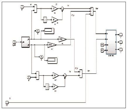
Figure 7. Control Block of 2 Level Inverter
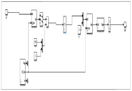
Figure 8. Block Diagram of Series Converter Controller
The proposed controller UPFC connected to the power generation system to eliminate voltage imbalance in the unit. UPFC component provides fast reactive power compensating the high-voltage power transmission systems. UPFC utilizes a set of controllable three-phase bridges to generate current that is added into a transmission line using a series transformer. The device controls active and reactive power flows in a transmission line.
In the Figure 5, the circuit breaker in the system is kept open and one side of the UPFC link is disconnected. The signal sent to the proposed controller (UPFC) is disconnected to show the voltage sag in the system. The system model is run in the Simulink software to show the waveform having voltage sag.
The Figure 9 shows the voltage sag in the generating system. Voltage sag is also known as voltage dip, which affects the system performance. Voltage sag is defined as decrease in the rms voltage for short time. Voltage sag is caused due to over load, short circuit or faults or due to starting of motors. One of the other causes can also be loose connection which leads to increase in source impedance. Voltage sag is caused when rms voltage decreases from 10 to 90 % of the rated voltage for one-half cycle to one minute. From the Figure 9, it is seen that the voltage when reached about 350 V in 0.3 seconds it is normal and stable and there is voltage dip in the waveform for few seconds. The dip in voltage if ignored, may interrupt the production with raw material loss in the production line and cause damage to electronic boards.
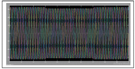
Figure 9. Waveform Showing Voltage Sag
The UPFC is connected to the circuit breaker keeping it open. Hence, the voltage sag is corrected, compensated and the sag in the voltage is removed.
In the Figure 4, the circuit breaker in the system is kept closed and one side of the UPFC link is disconnected. The signal sent to the proposed controller (UPFC) is disconnected to show the voltage swell in the system. Here, the UPFC is detached and the abnormal load is sent to the system. The system model is run in the Simulink software to show the waveform having voltage swell.
The Figure 10 shows the voltage swell in the power system. Voltage swells are caused by decrease in load on a circuit with a damaged or poor voltage regulator or loose connection. This issue causes flickering of lights or data loss, damage of sensitive electrical equipment. Hence, it is very important to solve the issues of voltage sag and swell.
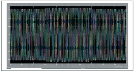
Figure 10. Waveform Showing Voltage Swell
In the simulation, the UPFC is connected to the system to eliminate sag and voltage swells. The circuit breaker is kept open to show voltage sag and kept closed to show voltage swell.
The Figure 11 shows the balanced waveform which has no voltage swell or voltage dip in the system. The voltage unbalance is eliminated using the proposed UPFC to the power system. Thus, the performance and efficiency of the system is improved.
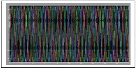
Figure 11. Waveform Showing Elminated Voltage Sag and Voltage Swell
In this paper, the power quality issues such as a voltage sag and swell are considered for analysis. The UPFC (unified Power Flow Controller) is a three-phase device, with a combination of series active power filter and shunt active power filter with common DC link. It is employed to eliminate voltage sag and voltage swell compensation on distribution network, current harmonics, compensate real and reactive power. In this work UPFC is modeled and simulated using MATLAB (SIMULINK) software and analyzed for voltage sag and swell compensation in distribution system. This will in turn maintain the voltage stability and improve the power quality and efficiency of the system.