Figure 1. Basic structure of DVR
Power quality is an extensive term to describe the effectiveness and its performances. The main task of power system is to provide their customer a continuity power supply forever, because the whole power system is a big network which includes different types of loads. At the instant of common coupling, connected sensitive loads in which voltage distortion in supply side or load side is highly repellent. Voltage dip is the most frequently arising power quality issue mainly occuring in distribution system due to faults, connecting nonlinear loads, since it is a main disturbance for domestic and industrial equipment. In this paper to diminish the voltage drop, fuzzy logic controller based dynamic voltage restorer is used in three-phase parallel distribution system. The Fuzzy logic controller is used to manage the DVR output. The performance evolution and result is simulated using MATLAB/SIMULINK. The Fuzzy control rule is optimized using Gaussian membership function by applying if-then rule.
Modern day power systems are complicated networks with hundreds of generating stations and load centers being interconnected through power transmission lines. An electric power system has three separate components power generation, power transmission and power distribution. Electric power is generated by synchronous alternators that are usually driven either by steam or hydro turbines. Reliability and quality are the two most important facets of any power delivery system. A power distribution system is reliable if all its customer gets uninterrupted power for 24 hours a day and 365 days a year. The power quality problems in power distribution systems are not new, but customer awareness of these problems has increased. Similarly there are set of conventional solutions to the power quality problem which has existed for a long time (Ghosh & Ledwich, 2012).
Power quality is a set of electrical boundaries that allows a piece of equipment to function in its intended manner without significant loss of performance or life expectancy. Power quality problems like voltage sag, swell, unbalance, interruption, flicker, harmonics, etc., create poor power quality. In this paper fuzzy logic controller based DVR is used to mitigate the voltage sag in distribution system. Fuzzy logic controller is used to control the output of the DVR, and output of this is applied to generate gate pulse for voltage source inverter.
The basic principle of the dynamic voltage restorer is to inject a voltage of required magnitude and frequency, so that it can restore the load side voltage to the desired amplitude and waveform even when the source voltage is unbalanced or distorted. The voltage assessment falls between 10% to 90% of the nominal voltage (IEEE Standards Association, 2009). The DVR can generate or absorb independently controllable real and reactive power at the load side.
The source of the injected voltage is the commutation process for reactive power demand and an energy source for the real power demand. The energy source may vary according to the design and manufacturer of the DVR (Sankaran, 2002). Some examples of energy sources applied are DC capacitors, batteries and that drawn from the line through a rectifier.
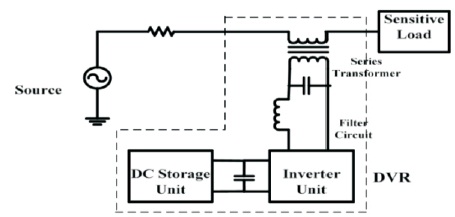
The basic formation of a DVR is given in Figure 1. It contains the following components-
Figure 1. Basic structure of DVR
The major purpose of the DVR is injecting the voltage of the required magnitude and frequency as preferred by means of the power system net. For the duration of the normal action, the DVR will be there in support mode. During the trouble in the system, the insignificant or rated voltage is compared by means of the voltage deviation and the DVR injects the divergence voltage that is essential by the load (Abed et al., 2017; Praveena & Kumar, 2017)
The voltage injected via DVR is articulated as;

where,
Vinj = required injected voltage,
Vload = desired load voltage,
Zload = load impedance,
Iload = load current, Vs = source voltage.
To control the dynamic voltage restorer, Synchronous reference frame theory based on battery supported is applied to execute the control method planned. The Feed-forward control performance utilizing dq0- transformation or generally called Park's Transformation is implemented at this time for DVR controller (Bangarraju et al., 2017, Saggu & Singh, 2015).
An essential segment of the control lane of the DVR is the sag detection circuit. Voltage sag has to be detected very quickly and corrected competently with the purpose of smallest amount of error. To start with the considered phase voltage is converting from abc reference frame to dq0 reference frame. From the time when the system and disturbance deal is balanced, the zero-sequence component becomes zero, so it will be ignored. The voltage sag is detected by comparing a situate of reference voltage in dq0 frame with deliberate RMS phasevoltages. The relation for recognition of sag is given by

Park's Transformation: In Electrical Engineering, Park's transformation (or dq0 transformation) is an arithmetical conversion method used to make simpler analysis of threephase circuits. The equations describing the transformation from abc to dq0 reference frame of three-phase voltage is,
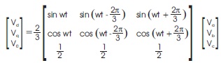
The DVR voltage as the frame of 'abc' is obtained by using reverse park transformation

The transformation is regularly used to make simpler examination of three phase piece of equipment or to formulate simpler calculations measured for the controloperation of three-phase inverter.
Fuzzy scheme is the rule based system based on the fuzzy interference and fuzzy rule represents awareness that is subjective. Fuzzy system is distinct by three section i.e.,
Fuzzy inference takes the inputs, applies fuzzy rule and gives the output. The degree of membership function is defined through a characteristics function called membership function (Das et al., 2018; Nabi & Singh, 2016). The characteristics function represents,
μA(u)=1, if u is an element of the set A
μA(u)=0, if u is not a function of the set A,
where 'A' is fuzzy subset of 'u'
Fuzzy logic controller uses very flexible set of IF-THEN rules and the solution is applied to the membership function. In this paper, sugeno type fuzzy controller also called as takagi sugeno fuzzy sytem is considered. In sugeno type system, multiple input and single output function used for the nonlinear system for approximate results, and the working of fuzzy controller is shown in Figure 2.
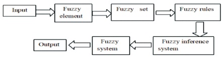
Figure 2. Basic Structure of DVR
We can take intermediate values like small, medium and large, error and change in error is consider as two input and one output is produced. Seven membership function is considered for each input and output and in sugeno type interference system square time of rule is created according to their membership function shown in Table 1.
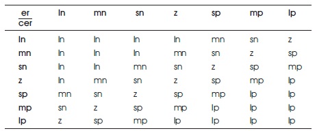
Table 1. FL Controller Rules
where,
er = error cer = change in error
ln = large negative lp = large positive
mn = medium negative mp = medium positive
sn = small negative
sp = small positive
z = zero
The rules are written as,
Fuzzy logic controller is used in this control model in order to reduce the error zero as soon as possible. Fuzzy logic designer for membership function for two inputs and one output shown in Figure 3, 4 & 5, and surface view of inputs and output is shown in Figure 6.
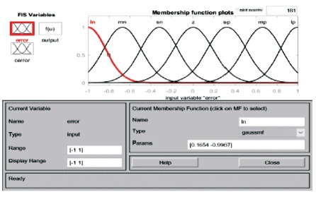
Figure 3. Membership Function Plots for Input Variable “Error”
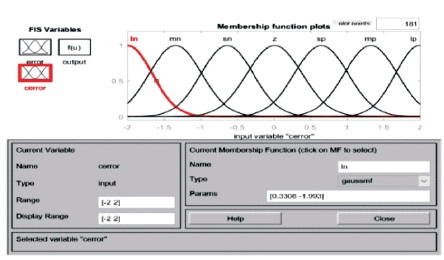
Figure 4. Membership Function Plots for Input Variable “Cerror”
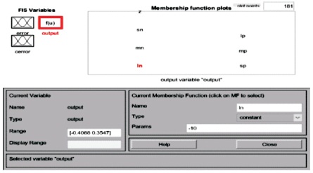
Figure 5. Membership Function Plots for Output Variable
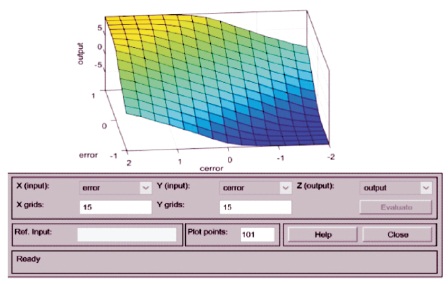
Figure 6. Surface View of Inputs and Output Function
In order to analyse the voltage sag, two parallel distribution feeder is considered as test system and feeder-1 creates a different time of fault, then the fault duration of voltage sag is automatically created in feeder-2. This system is implemented in MATLAB Simulink as shown in Figure 7 to learn the analysis of voltage sag and act of DVR, and also its control strategy is to improve the power quality problem.
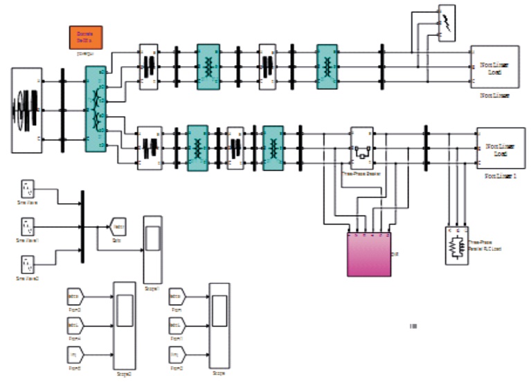
Figure 7. Simulation Model of Test System
To diminish the voltage sag an error signal is obtained by comparing a reference signal to supply voltage measured at the load side. The error signals is then proceeded to fuzzy logic control where error signal is evaluated with change in error signal by applying a fuzzy rule and obtained an output signal shown in Figure 8. The output signal is converted to abc frame signal and feed to the PWM generator. This signal is sent to IGBT voltage source inverter. Voltage required for the compensation is obtain by output of VSI, which is then feed to injected transformer primary winding as shown in Figure 9.
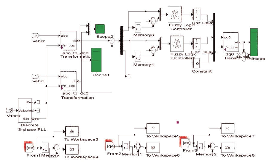
Figure 8. Model of Reference Frame Theory Control Method of DVR
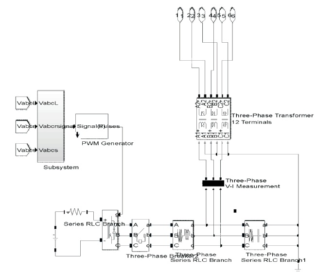
Figure 9. DVR Connection Model
The different type of fault is created in feeder-1 to analyze the sag at the duration of 0.4 seconds to 0.6 seconds with fault resistance of 0.001 Ω and ground resistance 0.001 Ω, and at the same time symmetrical and unsymmetrical voltage sag is occurred in second feeder. Using DVR this drop is compensated. Figure 10, 11 and 12 shows SLG, LLG, and three phase to ground faults and the sag in feeder-2 is cleared showing source voltage, load voltage and injected voltage waveform, by injecting the voltage when the load side voltage sag is clear, also ABC to dq0 reference signal is shown in Figure 13 and also the FFT analysis is shown in Figure 14, where the voltage harmonics is 0.61% which is in the range and very small.
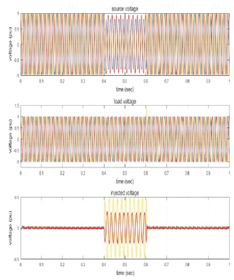
Figure 10. Single Line to Ground Fault Sag Clearing
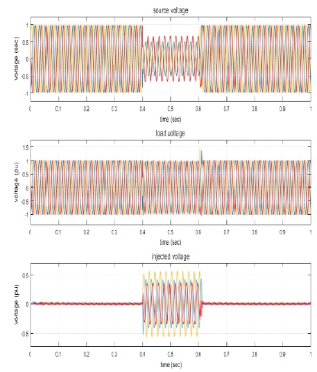
Figure 11. Double Line to Ground Fault Sag Clearing
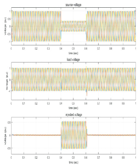
Figure 12. Three Phase to Ground Fault Sag Clearing
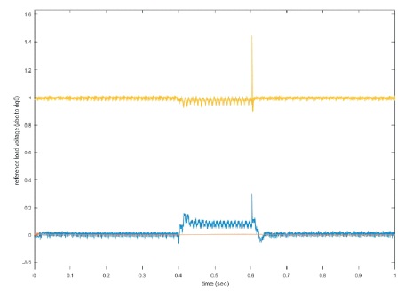
Figure 13. Reference Load Voltage (abc to dq0 Transformation)
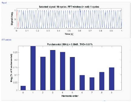
Figure 14. FFT Analysis
Table 2. FL Controller Rules
This paper present the performance of voltage sag reduction by using a fuzzy logic controller based dynamic voltage restorer. Voltage sag is frequently occurring power problem due to faults occurring in system, which affects the performance of the system. Fuzzy logic organizer is used in this and the main aim of the required controller is making the error to zero as soon as possible. Fuzzy logic is used for the following beneficial reasons.
The simulation results showed that the load voltage has been compensated using the dynamic voltage restorer, and also the voltage harmonic is reduced i.e. 0.61% which is very less. This entire attempt is done by MATLAB/ SIMULINK program.