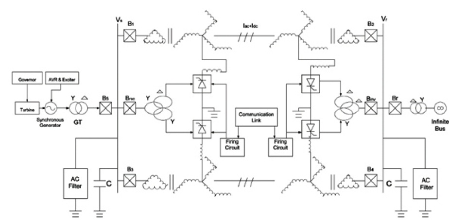
Figure 1. Basic Scheme for Simultaneous AC-DC Transmission
It is difficult to load long extra-high voltage (EHV) AC lines to their thermal limits as a sufficient margin is kept against transient instability. In the model proposed in this the paper, it will be feasible to load these lines near to their thermal permissible limits. This paper gives us the feasibility of converting a double circuit AC line into composite AC–DC power transmission line, without constructing a separate DC line, to get the advantages of parallel AC–DC transmission for improving stability and loadability of a transmission line. There is no need for the alteration of conductors, insulator strings, and towers. An analytical model is established for the loadability and transient stability analysis of the simultaneous ACDC transmission system. The validation of these models is carried out by comparing the results obtained from the application of the models with already published results. Simulation has been carried out in MATLAB software package. Both loadability and stability models are also applied to a realistic system. The benefits of the simultaneous AC-DC system are evaluated and the results are critically discussed.
If it wasn't for Electricity, today's world economy would have been in great danger. Ever since the introduction of electricity, mankind has shown a great leap in agricultural and industrial sectors. Electric power transmission is nothing but transfer of electrical energy, from generating power plants, usually sited in remote locations, to electrical substations that are located near the demand center. It has been observed that the transmission of bulk power through the installed high capacity AC voltage lines experiences a certain upper limit beyond which the system runs into transient instability. Consequently, the lines are never loaded up to their maximum thermal limit rather much less than that. This is a major barrier for finding ways and means to raise the capacity of the existing EHVAC transmission line prototype. Moreover, environmental constraints have greatly limited the realization of new power corridors with increased load capacity. Hence the solutions are more or less limited to enhancing power transfer without any significant structural changes. This has given rise to the introduction of HVDC systems. Conversion into DC has considerably decreased per unit losses, improved power quality, and emphasized the reliability of the line. Despite the greater cost of conversion equipment, HVDC systems have proven to be safe, cost-efficient, and environmentally friendly. As compared to HVAC systems, they are encountered with decreased stability problems. However, HVDC system fizz to make any flattering contribution to the system synchronizing torque and ultimately raise the margin of instability. This provides the alley for researchers and engineers to think beyond the obvious and establish a scheme that would allow HVDC power transfer across an already fully functioning HVAC line, hence giving rise to the idea of combined HVAC and HVDC transmission. Such a scheme would significantly help in removing problems of transient instability. Control strategies could be established and operated on the HVDC system to magnify the synchronizing and damping torques. This would further stabilize the AC system and eliminate any requirement for extra reactive power in converter controllers. Problem statement in the existing transmission system, long extra-high voltage (EHV) AC lines cannot be loaded to their thermal limits to keep sufficient margin against transient instability. With the scheme proposed in this paper, it is feasible to load these lines near to their thermal limits. The conductors are allowed to carry usual AC along with DC superimposed on it. By doing so, the capacity of the transmission lines can be increased by nearly 70% of that if only AC is transmitted.
Constantly increasing demand along with limitations of constructing new transmission infrastructures has increased the need to make use of the power transmission systems at their maximum level. Increasing the transmission capacity of the existing transmission line has never been more important because of the rising cost of building new transmission lines and the difficulties to obtain new transmission way. Power system engineers are in continuous search for effective ways to obtain the full capacity of the existing transmission lines. Every transmission line has an upper limit for loadability mainly governed by three influential factors namely; thermal limit, voltage drop limit, and steady-state stability limit (Gutman et al., 1979). The length of the transmission lines also supervises the loadability limiting factors, and hence thermal limit, voltage drop limit, and steady-state stability limit factors are applicable for up to 80, 320, and beyond 320 Km length of the transmission line, respectively (Kundur, 1993). Constructing a new transmission line and operating it in parallel with the present AC transmission system can increase the power transfer. One method is using a parallelsmall power DC link and it is presented (Lucas & Peiris, 2001). The parallel DC link can improve the loadability and dynamic stability of the AC transmission system. A second line, working in parallel, can raise the power transmission capacity and guarantee the service continuity during maintenance and it can meet the future demand (Bakshi, 2009). Construction of a new transmission line will further strengthen the existing AC transmission system, increase the operational reliability of the system, and overcome the overall transmission system restrictions (Ingemansson et al., 2012). From stability point of view, DC link parallel operation with AC transmission line (i.e. AC-DC parallel transmission system) is more advantageous than AC-AC parallel transmission lines. In the case of the AC-DC parallel system, the DC link power flow is highly controllable through converter operation. The effect of controlled DC link on system stability and damping also depends on system working conditions. A generalized state-space model of the parallel AC-DC power system is derived (Dash et al.,1976). An HVDC controller which improves stability at one operating condition may have damaging effects at other operating conditions. Therefore, an adaptive control mode would be needed for the HVDC controller to improve system stability over a wide range of system performance. By constructing a new transmission line and operating it parallel to the existing line, an improvement can be achieved in the loadability and stability of the power transmission system (Yusof & Sivadass, 2006). Transmission line compensation suggests a modification in the electrical characteristic of the transmission line to increase power transfer capability and stability. In the case of series compensation, the objective is to reduce the transfer reactance i.e., electrical length of the line at power frequency utilizing series capacitors. This results in enhanced system stability, and increased power transfer capability of the line and a reduction in the power transmission angle at a given level of power transfer. In Kosterev et al. (1996), a step by step method is developed for rating and sizing the controlled and conventional series compensations. To increase the load transfer capability of a transmission line, determination of exact location and amount of series compensation is an important issue and in the light of this issue, some analytical tools are presented in Rajarman et al. (1998) for increasing the steady-state power transfer limit. These tools can estimate the change in operating boundary limits of the transmission system due to the application of series and shunt compensation. Although series compensation improves the performance of a system with a long transmission line, it causes two protection problems. These two problems are considered as limiting factors for designing the amount of series compensation in an electrical network (Larsen & Baker, 1980). A simultaneous AC-DC power transmission system to increase the power flow through the existing line is proposed by Rahman and Khan (2007). The simultaneous AC-DC power flow derives the benefit of a parallel HVDC line without constructing the separate DC line. In this system of power transmission, existing AC line conductors are used to carry AC power along with DC power and there is no need for any modification in the size of conductors, insulator strings, and tower structure of the original line. Another paper presented by Rahman and Khan (2008), performed a feasibility study for the possibility of small power tapping from a simultaneous AC-DC transmission. Babu et al. (2012), have studied two control modes such as independent control and coordinated control of AC and DC power transmission to maintain the thermal limit line current in case of simultaneous AC-DC system. A comparison of power flow is shown among pure AC, HVDC, and simultaneous AC-DC systems through the same transmission line in Sherkhane and Bachawad (2015). Basu (2009) proposed a methodology to improve the stability of the simultaneous AC-DC system where the system is no more AC-DC system after clearing the fault until the system enters into the normal state. In this proposed methodology, AC-DC composite system is converted into the DC system, by tripping AC circuit breakers, just after clearing the fault and when the system becomes healthy the AC breakers are turned on. The application of this methodology will need a special control mechanism for a circuit breaker operation. A further analysis presented (Alam & Ahsan, 2014a, 2014b, 2017; Basu, 2009; Hammad, 1999; Muni et al., 2011) has observed that for a transient fault the critical clearing time varies with the variation of post-fault DC power flow and maximum rotor angle deviation as well. Numerical analysis using MATLAB Simulink (Grainger & Stevenson, 1994; Muni et al., 2011; Verma et al., 2014) has also shown that the conversion of AC system into a simultaneous AC-DC system can improve the transient stability and damp out oscillation.
When DC is injected into AC and transmitted at the same time through the same transmission line, then the system is called a simultaneous AC-DC system. From an operational point of view, this system is very much close to AC-DC parallel system and the difference is that simultaneous ACDC has no separate DC line. Likewise, no alternations are needed in the tower structure, conductor spacing, and original conductor lines. The schematic diagram of the simultaneous AC-DC system is presented in Figure 1. The double circuit AC line is carefully converted into an integrated AC-DC line allowing an even distribution of the DC power across the three lines. Every line now carries AC along with one-third of the DC component. The equalivant circuit of the AC-DC system is shown in Figure 2.
Figure 1. Basic Scheme for Simultaneous AC-DC Transmission
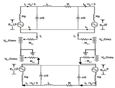
Figure 2. Equivalent Circuit of the AC-DC System.
As can be seen from the circuit, the DC power is acquired by converting a portion of the AC power from the generator bus through the line commutated 12-Pulse Rectifier Bridge and injected to the system through the neutral point of the secondary winding of a zigzag transformer. At the receiving end, the DC portion of power is taken away from the neutral point of another zigzag transformer and converted into AC before feeding to the infinite bus. Two converter stations with converter transformer, one for AC to DC conversion at the sending end, and another one for DC to AC conversion at the receiving end of the transmission line are needed (Hammad, 1999; Muni et al., 2011). Zigzag serves the purpose of equal distribution of DC in all three phases since resistance is the same in all the three windings of the secondary winding (zigzag) of the transformer. Due to the flow of DC currents of equal magnitude in the opposite direction, the fluxes produced by such currents flowing in each winding becomes zero, hence avoiding transformer saturation due to DC current.
A simple AC power system, transmitting power from a generator to an infinite bus through a transmission line is depicted in Figure 3. The power flow between the two buses, 1 and 2 (Grainger & Stevenson, 1994) can be expressed as,
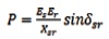
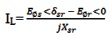
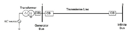
Figure 3. Pure AC Power Transmission System
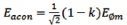
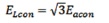
The AC voltage of simultaneous AC-DC in terms of pure AC system voltage is as follows,

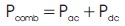
The combined power flow in a simultaneous AC-DC system is
The modified power flow model due to AC in the simultaneous AC-DC system, Pac, may be expressed as,

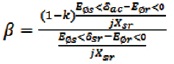
The evaluation of the power flow variation due to the ACDC simultaneous flow would be easier if Pac is expressed in terms of the power flow of the pure AC system. With this objective, a proportionality constant, β is introduced as a ratio between the current, IAC, due to AC voltage in the AC- DC system and the current, IL, of pure AC system.
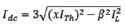
To express the DC power in terms of the power of pure AC system, the DC voltage and current must be expressed in terms of those of the original AC system.

Expressing IAC and It in terms of IL and thermal limit current, respectively, Equation (9) may be written as,
Let β be the ratio between the original AC current in the AC-DC system and the original current in the pure AC system.
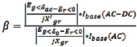
The combined power flow in AC-DC system can be expressed in per unit as,

The basic scheme for simultaneous AC-DC power flow through a double circuit AC transmission line, considered is already presented in Figure 4. In this system, a 2750 MVA (5*550), 24 kV synchronous machines are feeding power to an infinite bus bar via a double circuit, three-phase, 400 VA, 50 Hz, 450 km AC transmission line. An ASCR twin bundle with the following line parameters is used in the line.
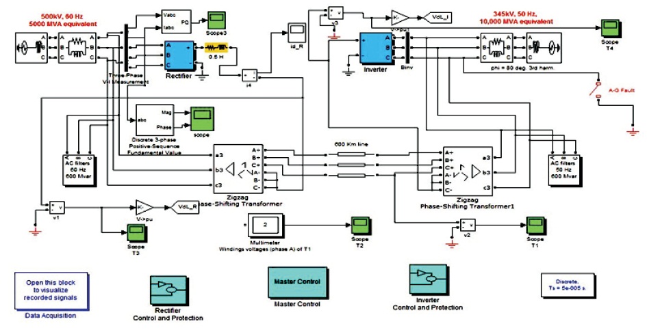
Figure 4. Simulink Model of Simultaneous AC-DC Transmission
System Parameters.
Z = 0.03252 + j0.33086 Ω/Km/phase/ckt
Y = j3.33797*10-6 s/km/phase/ckt
Current carrying capacity of each sub conductor = 0.9 kA
Thermal limit of the conductor, = 1.8 kA/ckt
As per expression of a simultaneous AC-DC system in equation 12, the total power flow through the AC-DC system (Pcomb) is greater than the power flow through the AC system, if and only if the factor ε is greater than unity where, ε is a function of k, α, and x. Yet, the simultaneous AC-DC system does not transmit higher power than the pure AC system for all values of k, α, and x. The total power flow through the combined AC-DC line for different values of k, α and x is evaluated and the results are recorded in Table 1.
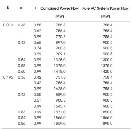
Table 1. Effect of the Values of k, α, x on Loadability
The system consists of a generating unit with a capacity of 2272 MW feeding an infinite bus bar via a double circuit, 500 kV, 60 Hz, 400 km transmission line. The total power and corresponding AC and DC power through the simultaneous AC-DC line are evaluated by varying the transmission angle only for a fixed DC voltage mix of 49.5 and results are presented in Table 2.
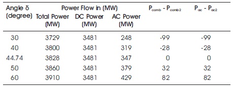
Table 2. Comparative Data Analysis
The impact of changing the transmission angle on the total combined power flow is presented for a given DC voltage mix. The line loading is assumed to be thermal limit loading and the considered DC voltage mix is 49%. The combined AC-DC power flow for different transmission angles is then compared with the pure AC power flow at 44.47 transmission angle. Due to stability considerations, the pure AC transmission angle of the given system cannot exceed 44.47 and different transmission angle and combined power, lodability results are shown in Table 3. Note that the variation of transmission angle δ, will vary the AC current, and hence the corresponding DC current will be adjusted so that the total current (AC + DC) doesn't exceed the thermal limit of the line.
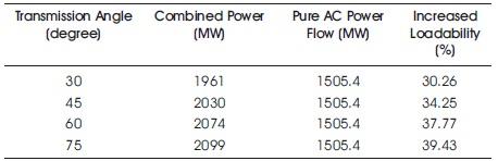
Table 3. Line Loading for Different Transmission Angle
The impact of varying the DC voltage mix on the combined power flow in the simultaneous AC-DC system is presented. The value of the transmission angle δ, is considered as 44.47 which is the same as the transmission angle of pure AC. Results of line loading with different DC voltage mix are shown in Table 4. It has been previously discussed that the AC transmission line cannot be loaded up to its thermal limit. However, in a simultaneous AC-DC system the magnitude of the current through the line can be up to its thermal limit.
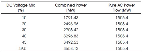
Table 4. Line Loading for Different DC Voltage Mix
Simultaneous transmission of AC-DC through a single transmission line is presented here. The analysis of AC-DC transmission is feasible to load the EHV lines near to the thermal limits, improvement of transient and dynamic stability. The upgrading of simultaneous AC-DC in a single transmission line improves the power transfer capability. A simulation study is being made for the coordinated control and also individual control of power transfer capability by maintaining the transmission angle. As the transmission angle increases the combined AC-DC power mix is increased. Similarly by increasing the power transfer capability the thermal limits of the transmission line within the prescribed limits is maintained.
P = Power flow through the line
Es = Sending end bus, bus 1, voltage
Er = Receiving end bus, bus 2, voltage
δsr = Angle between Esr and Er
Xsr = Line reactance
EØs = phase voltages of the sending end buses
EØr = phase voltages of the receiving end buses
EL = Line voltage for pure AC system
Eacon = AC phase voltage for simultaneous AC-DC system
ELcon = AC line voltage for simultaneous AC-DC system
It = Total line current of a simultaneous AC-DC transmission system.
Ibase (AC) = Base current for pure AC system
Ibase (AC-DC) = Base current for simultaneous AC-DC system
Pbase = Base power