[1]
This paper presents a novel concept of Unified Power Quality Conditioner (UPQC). In steady state conditions, the series compensator is in idle mode and the shunt compensator is involved in reactive power compensation. This paper addresses the reactive power compensation capability of both the compensators in steady state conditions. The problem of UPQC placement is formulated as a single objective problem. UPQC allocation in the distribution system is addressed by Sine Cosine Algorithm (SCA) with the objective of minimizing the losses and improving the voltage profile. Suitable Load Flow method is applied to incorporate the complex voltage and reactive power injected by the series and shunt compensator, respectively. The proposed algorithm is tested on standard distribution systems.
The need to address many problems of power quality has led to the development of the device known as UPQC. UPQC [5] is a multi-tasking device. The key elements of UPQC are shunt compensator and series compensator. Series compensator functions as a series voltage compensator in case of sag/swell. Shunt compensator functions as harmonic current eliminator and also load reactive power supporter. During sag/swell conditions only, the series compensator comes into picture and acts as voltage compensator. The rest of the time it is in idle mode. To do away with this functionality of UPQC and to utilize the series compensator in steady state, it is necessary for the series compensator to provide compensation in steady state conditions. The maximum utilization of UPQC in steady state is illustrated in [3], [6], [8]. The provision of UPQC to provide continuously variable reactive power is an advantage over capacitors. The problem of optimal location of capacitors is presented in [10]. In case of light load or heavy load conditions capacitors provide the same fixed compensation. Hence, the problem gets aggravated. The optimal allocation of UPQC in distribution systems can solve the problem of reactive power compensation as per load var ying conditions. UPQC performance in large distribution system is addressed by modeling UPQC in the Load Flow method. UPQC allocation problem is solved by using various optimization methods. Few of them to be mentioned are Particle Swarm Optimization method, Differential Evolution Algorithm, etc. In this paper, Sine Cosine Algorithm is used for optimal allocation of UPQC in radial distribution system. Sine Cosine Algorithm is a population based Heuristic Algorithm. The change in position of the search agents involve sine and cosine terms. Hence it is called as Sine Cosine Algorithm.
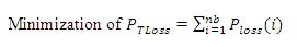
The objective of UPQC placement in the radial distribution system is minimization of real power losses, which is given by equation (1),

where PTLoss : Total real power loss;
PLoss : Real power losses in the branch; and
nb : Total number of branches.
The inequality constraint associated with load bus voltage is given as follows;
1. The load bus voltage magnitude should be kept within the acceptable operating limits. That is ± 5% of the nominal voltage value.
2. The inequality constraint associated with reactive power compensation is given in equation (4),
where QUPQC is the reactive power supplied by UPQC;
QD is the sum of reactive power demand.
3. The optimizing constraint (voltage constraint) While optimizing, the voltage at the desired location should not exceed 1 p.u.

To assess the real power losses without and with the inclusion of UPQC in the radial distribution system, the Load Flow method adopted is illustrated in the following section.
There are different Load Flow methods which are reported in [4], [12]. The Load Flow method used in this paper is based on calculation of Bus Injection to Branch Current (BIBC) matrix and forward sweep.
The equation relating the load currents with the real and reactive power loads at the m bus is given in equation (6),
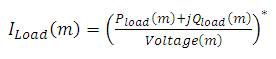
where Pload(m) : Real power load demand;
Qload(m): Reactive power load demand; and
Voltage(m): Load bus voltage.
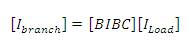
BIBC matrix gives the relation between load currents and branch currents. The corresponding equation (7) is given as,
The voltage at the ith load bus is obtained by equation (8),
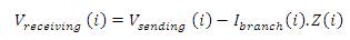
where, Vreceiveing (i): receiving end node voltage;
Vsending (i) : sending end node voltage;
Ibranch (i) : Branch current; and
Z(i) : Branch impedance.
UPQC is a hybrid device. It is a versatile device among the available Distributed Flexible Alternating Current Transmission System (DFACTS) devices to compensate several power quality problems, simultaneously. It consists of a shunt compensator and a series compensator as shown in Figure 1. The shunt compensator is the most promising to meet the reactive power needs of the system. The series compensator is the most suitable to handle voltage related problems. The main components of UPQC are listed below.
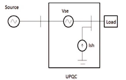
Figure 1. UPQC Structure
One of the VSC functions as shunt compensator and the other as series compensator. It converts fixed supply voltage stored into variable supply voltage.
The AC voltage supplied by VSC is stepped up by using injection transformer to the desired voltage level.
It filters out the harmonics present in the output of the VSC.
The main function of energy storage unit is to provide real and reactive power for compensation. It includes lead acid batteries, flywheels, DC capacitors, and super capacitors. DC to AC conversion is required for batteries whereas, AC to AC conversion is required for flywheels.
The control unit is the most important part of UPQC system.
The problem of UPQC placement is formulated as a single objective nonlinear problem. The series compensator is modeled as the source of real and reactive power. The phasor diagram of series voltage injection is given in Figure 2.
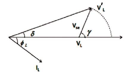
Figure 2. Phasor Diagram for Voltage Injection by Series Compensator
The new voltage obtained after injecting the voltage by the series compensator is given in equation (9),
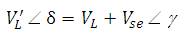
The complex power injected by the series compensator is obtained by equation (10),
where Vse is the voltage injected by the series compensator;
Ibranch is the branch current in which series compensator is branch included.
The shunt compensator is modeled as the source of constant reactive power. Due to voltage injection by the series compensator, the voltage is changed to VL'. The L reactive power injected by the shunt compensating device after placing UPQC is given in equation (11),
where Ic' is the compensating current after series compensation as given in [10].
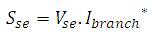
It is a population-based optimization technique [9]. The four main parameters emphasized in Sine Cosine Algorithm are r1, r2, r3, and r4. The parameter r1 decides the search agents' position, which could be either in the space between the solution and destination or outside it. The parameter r2 describe the movement should be towards or outwards the destination. The parameter r3 brings a random weight for the destination in order to highlight (r3 >1) or de-emphasize (r3 <1) the effect of destination in defining the distance. Finally, the parameter r4 determines the selection of sine and cosine components. A conceptual model of the effects of sine and cosine functions within the range [-2, 2] is given in Figure 3.
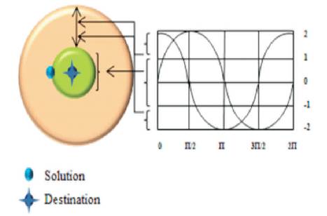
Figure 3. Sine and Cosine Functions in the Range [-2, 2] demonstrating Exploitation and Exploration of the SCA Algorithm
Sine Cosine algorithm generates and improves the set of random solutions for a given problem.
Depending on the values of sine and cosine functions, different regions of the search space are explored.
If the function values are in the range [-1, 1], the algorithm exploits the search space.
If the function values are in the range (1, 2] and [-2, -1), the algorithm explores the search space.
The adaptive range defined by equation (12) helps in the transition from exploration to exploitation.
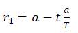
where t is the current iteration;
T is maximum iteration; and a is a constant.
The search agents update their position as given by equation (13),
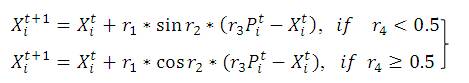
where Xit is the position of the current solution in ith dimension at tth iteration;
Pit is the position of the destination point in the ith dimension; r1, r2, r3 and r4 are random numbers.
Step 1 : Initialize the number of search agents, maximum iterations, and dimension, minimum and maximum limits of complex voltage injected by series compensator. The dimension of the problem is 3.
Step 2 : Generate the matrix of the order [m x n] where m denotes the number of search agents and n denotes the dimension of the search space. Here the dimensions are locations and complex voltage injected by the series compensator.
Step 3 : Run the load flow by injecting the complex voltage generated at the corresponding location. Calculate the reactive power to be compensated by the shunt compensator by using equation (11).
Step 4 : Check for the voltage constraint. The voltage constraint imposed is the voltage at the desired location should not exceed 1 p.u. Find the fitness. Here the fitness is minimization of real power losses. The fitness corresponding to the search agents which violate the voltage constraint is set to base case real power loss.
Step 5 : Obtain the best search agent, which has better fitness value.
Step 6 : Iteration count is set to one.
Step 7 : Update the position of each search agent as given in equation (13). Check, whether the newly generated search agents are within the limits.
Step 8 : Calculate new fitness values for the new positions of all the search agents. The new fitness values are updated, if they satisfy the voltage constraint. Update the best search agent with better fitness value.
Step 9 : Increment the iteration count. If iteration count does not reach its maximum, then repeat from step 6.
Step 10 : The best search agent gives the location and complex voltage injected by series compensator.
The bus systems used to validate the results are 33-bus and 69 bus systems. The data concerned is given in the following sections.
The data of the system is acquired from [1]. The base voltage is 12.66 kV. The real and reactive load of the system is 3715 kW and 2300 kVAr, respectively. It has 33 buses and 32 branches. 21 out of 33 buses of the distribution system have under voltage problem. The results of UPQC installation are detailed in Table 1. Voltage profiles of 33-bus system without and with consideration of UPQC are given in Table 2.
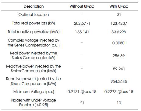
Table 1. Results of 33 Bus System
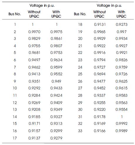
Table 2. Voltage Profiles of 33 Bus System without and with Consideration of UPQC
The data of the system is obtained from [2]. The base voltage is 12.66 kV. The total load on the system is 3802.19 kW and 2694.6 kVAr. It has 69 buses and 68 branches. 9 nodes out of 69 nodes of distribution system (13.04%) have under voltage problem. The results of UPQC installation for 69 bus radial distribution system are detailed in Table 3. Voltage profiles of 69-bus system without and with consideration of UPQC are given in Table 4.
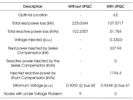
Table 3. Results of 69 Bus System
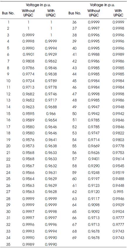
Table 4. Voltage Profile for 69 Bus System without and with Consideration of UPQC
From Table 5, the real power loss reduction is 39.1% by using Sine Cosine Algorithm.
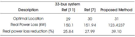
Table 5. Comparative Results of 33 Bus System
From Table 6, the real power loss reduction is 52.19% by using sine cosine algorithm.
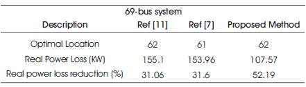
Table 6. Comparative Results of 69 Bus System
The reactive power compensation capability of series and shunt compensators in steady state conditions is presented with suitable bus systems. UPQC incorporates the reactive power compensation capability with series compensator by injecting the voltage and with shunt compensator by injecting the reactive power. The voltage and reactive power are injected in such a way that, the voltage at the desired location is maintained at 1 p.u. in steady state conditions. UPQC allocation in radial distribution systems is dealt with Sine Cosine Algorithm to reduce the real power losses and improve the voltage profile. The results are compared with the results of other methods. The results obtained shows that, the proposed method is more effective than the other methods.