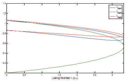
Figure 1. PV Curves for Base Case Schedule
The application of competitive market principles to the operation of power systems has resulted in stability margins being reduced to responding market pressures, which demand greater attention to reduced operating costs. As the overall stability limits can be closely associated with the voltage stability of the network, the incorporation of voltage collapse criteria and tools in the operation of power systems is becoming an essential part of new energy management systems. The possibility of uncertainties incidence in power system operation cannot be avoided in security studies. The load withdrawals and generation schedule are unpredictable in the market environment. In addition, the contingencies cause to reduce security margins further. In this paper, with the help of an illustrative example, the generation schedule, the importance of proper generator excitation, and how it will impact on reactive power control from a source is explored.
For the reliable operation of electric power systems, the reactive power balance is essential. In history, various power system blackouts including India had happened due to inadequate reactive power reserve. Voltage collapse was a causal factor in the blackouts, namely in August 4, 1982, in Belgian; August 22, 1987, in West Tennessee; July 2, 1996, in Washington State Community College (WSCC); August 10, 1996, in West Coast; July 12, 2004, in Greece. Voltage collapse also factored in the blackouts of December 19, 1978, in France; March 2, 1979, at Zealand in Denmark; July 1979, Canada in B. C. Hydros north coast region; December 27, 1983, in Sweden; May 17, 1985, in South Florida; July 1985, in Czechoslovakia; July 23, 1987, in Tokyo; January 12, 1987, in Western France; March 13, 1989, in Québec; August 1992, in Southern Finland; August 14, 2003, in North America; August 28, 2003, in London; September 23, 2003, in Sweden and Denmark; and September 28, 2003, in Italy. In addition to these, some other blackouts in worldwide have been given in [4, 19].
Some of them are reported with comprehensive analysis of various reasons for these failures in literature. Economical restrictions with restructured environment, inadvertent operation of protective schemes, ineffective design of conventional load-shedding approaches and insufficient reactive power sources are some of the most main reasons initiating these blackouts. Among all these reasons, lack of reactive power support is a major significant factor for voltage instability. For the reliable operation, both the active and reactive power consumptions have to be controlled effectively. However, due to strong dependency of voltage profile on reactive power consumption, it is possible to maintain proper voltage profile by the compensating the reactive power throughout the network [10].
According to IEEE/CIGRE task force, voltage stability is defined as the power system capability to regain steady voltages profile throughout the network after being postdisturbance from a given pre-disturbance state. It depends on the ability to maintain/restore equilibrium between load demand and generation in the network. Particularly, the instability can occur due to uncontrollable voltage profile at some of the buses in network. Due to instability, load curtailment may need to impose in some areas/zones or requirement of optimal switching operations in transmission system with fast-acting protection devices. In the absence of these preventive/corrective actions, the loss of synchronous can take place
The generators absorb and also generate VAR based on the excitation conditions. The transmission lines can be able to support VARs under lightly loaded conditions and absorb VARs under heavily conditions. At any given point of time, the power system can experience various voltage levels at various locations. In general, the load consists of both active and reactive components. The transmission of power over Alternating Current (AC) circuits involves reactive components. The generation of power too contains the reactive participation. Hence, it is important and vital to monitor and control reactive power resources and reactive power consuming elements (sink) to maintain proper voltages in the grid within safe and secure limits. Reactive power control, thus forms the prime concern of large power grids.
In general, under peak load conditions, voltages are high at reactive source points and are low at load points and the direction of reactive power flow is from source to the load, whereas, under the off-peak conditions, the reactive power flow is from load points to reactive consuming points [15]. The transmission of VARs over transmission elements in peak load conditions further burdens the transmission elements and as a result, the voltages at the load end become further less. Hence it is desirable to meet the reactive power requirement locally and necessary planning of reactive compensation to be carried out. Even at nominal frequency and satisfactory voltage operating conditions, voltage collapse cannot be ruled out as voltage is a local phenomenon.
The better voltage profile can be obtained irrespective of loading conditions by adopting best practices in reactive power management. On the other side, the reactive power injection at a node can be controlled by regulating the voltage also. This is the major difference between voltage control and reactive power management in power system operation. But all the practices have their own limitations and advantages. In general, the voltage control by managing reactive power support is restricted due to limited reactive power sources in the network and similarly the control of reactive power is also limited due to acceptable voltage limitations in the system. So the stability management is possible either voltage control or reactive power control but not with the both measures. In the case of the transmission system, the control would be implemented on the system voltage.
As briefed in introduction, the physical and financial flows are controllable significantly by optimizing reactive power (VAR) reserves in the network. Traditionally, the primary objective of VAR planning is to install minimum number of supporting devices towards feasible voltage profile across the network at normal as well as contingency cases. But the introduction of a Flexible Alternating Current Transmission System (FACTS) devices concept has changed the entire methodology of this problem via providing dynamic reactive power control/support as required in the modern power systems. The great and significant work has been done on this subject [6, 8] including reactive power planning strategy to avoid voltage instability [1]. Integration of FACTS devices as a counter and effective measure for voltage instability can be found in [21]. In [16], based on novel VAR spot price index, the Static VAR Compensator (SVC) optimal location is identified. Similarly, the SVC optimal location towards maximization of transmission loadability is proposed. In [11], the SVC controls are optimized to get stabilization in the event of lack of damped inter area oscillations as well as to improve the power system power quality [2, 7].
In all the above sited works, as well as in [12], the normal operating condition is only considered to voltage stability enhancement. The location and size of SVCs have been discussed in details in both transient and steady states [17]. Recently, new mathematical approaches for the voltage stability problem have been developed with the consideration of voltage stability constraints [3, 18], which provides more realistic solutions for the VAR planning problem. However, by satisfying all the specified voltage stability limitations, the solutions of these methods have become too expensive due to integration of more reactive power controlling devices.
In [21], a new formulation and solution method are presented for the VAR planning problem, including FACTS devices, by considering the issues just mentioned. Basically, Static VAR Compensator is a shunt integrated FACTS device, which can be capable of all possible benefits of FACTS devices [9, 14]. From all these works, it can be concluded that VAR support and management can be done by FACTS devices effectively and hence, there is a possibility in maximizing the network physical flows. In addition, the reactive power support becomes an ancillary service in market environment and there is a need to minimize reactive power procurement form VAR service providers by extracting more support from FACTS devices.
Unfortunately, the reactive power became one of the major ancillary services to be procured from its service providers in most of the electricity markets. The reactive power producers in the network can be mainly either generators, synchronous condensers or FACTS devices. By extracting optimal output from VAR supporting/controlling devices, more VAR output of generation companies (GENCOs) can be decreased and results in reduced reactive power cost. This work deals with only generation companies considered for reactive power cost payment with an assumption of single-sided auction mechanism, in which only generation companies (GENCOs) are the competitors in electricity markets.
It is worthwhile to investigate the change in generation schedule impact on voltage stability. Due to strategic bidding, the generation schedule is always time-variant and is dependent on market participant's decisions. A well-known fact is that the market schedule will be based on economic grounds and hence, the unpredictable generation schedule and load withdrawals can directly affect the system loadability. In order to clear this statement, an illustrative case study has been performed in the next preceding section.
In order to understand clearly, the following studies are considered for both changes in generation schedule as well as line outages. In order to illustrate, IEEE 6-bus system is selected and data is given in [20]. The base system has 210 MW real power and 210 MVAR reactive power demand. The case studies are done using Power System Analysis Tool box (PSAT) [5].
The given generation schedule PG1 = 100 MW, PG2 = 50 MW, and PG3 = 60 MW is considered in this case study. In order to determine maximum loading capability of the transmission system, the Continuation Power Flow (CPF) has been performed. For a critical loading parameter λ=3.4578 p.u., the system has been collapsed and the corresponding Pressure Volume (PV) curves have been illustrated in Figure 1.
Figure 1. PV Curves for Base Case Schedule
The new generation schedule is taken as PG1 = 50 MW, PG2 = 88.01 MW, and PG3 = 71.93 MW. For a critical loading parameter 3.4578 p.u., the network is collapsed and the corresponding PV curves have been illustrated in Figure 2.
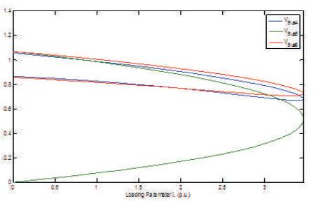
Figure 2.PV Curves for Change in Schedule
Most of the researches in any kind of problem consist contingency studies to validate their work under abnormalities also. Yes, it is required to understand the transmission system support to a particular operating state in any planning and operational studies. As per maximum power transfer theorem, the network impedance should be equal to load impedance to get a maximum transfer limit. Under line outages, the network impedance is less than load impedance and hence it causes reduction in the maximum loadability.
Hence the (N–1) line outage contingencies are imposed in the above cases independently. The impact of line outages in terms of reduction in loadability for base case schedule as well as for change in schedule is given in Figure 3. Based on the maximum loadability, reduction the line outages are also ranked in the tables. Observing in two two case studies, based on reduced values in Critical Loading Margin (CLM), the line 2 – 4 is ranked as #1, i.e., critical line in the system.
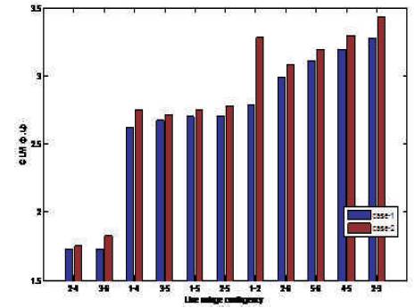
Figure 3. Variation in CLM for Two Generation Schedules
This case study is selected particularly to show the effectiveness of proper excitation control and its requirement in this competitive era. The reactive power generation is highly effected by voltage control, i.e. excitation at generation side, compensation at transmission and controlling devices at distribution side. The minimum reactive power output from a generator can achieve either by proper excitation control or integration of reactive power compensation devices.
A simple two-bus test system has been considered. The simulations are performed using PowerWorld simulator [13]. The generator at bus 1 is assumed as reference bus as well as power producer in the market environment and the load bus 2 is considered as simply rest of the system. With 300 MW power injection at bus 1 and withdrawal at bus 2 is planned under power wheeling option in the market. The reactive reserve in the rest of system is treated as VAR source as shown in Figure 4. Since the transmission line is assumed as purely reactive circuit in nature and hence real power loss will be zero in the system.
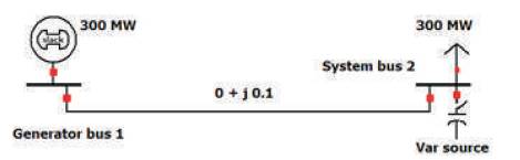
Figure 4. Two-Bus Test System
The system voltage is supposed to maintain at 1.0 p.u. either by independent control of reactive support from system or generator voltage control or by combination. Two scenarios have been studied, i.e., without and with reactive power support at system bus 2. In order to transfer the scheduled output from generator bus 1, it is required to produce more reactive power at a low terminal voltage and it decreases with the increment in terminal voltage. This can be observed in Figure 5 as without reactive support Qsup from the system and the situation is further impacted with Qsup from system.
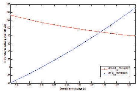
Figure 5. Reactive Power Output from the Generator Bus
Hence the generator excitation should control properly to produce minimum reactive power so that, the possibility of reactive power cost can decrease significantly.
In the present scenario, the power producers are changing their bid curves just to get desired MW clearance from the market. As mentioned earlier, if any generators' terminal voltage is not maintained at required level, the possibility of high reactive power output can increase and he can get more profit even though system operates at high voltage in security level. So the payment for reactive power from a generator source should redefine at an improper voltage level situation. The increment in reactive power cost due to improper voltage level is supposed as to be a penalty to such generators. The other possibility to reduce reactive power output from a source is such that the system should equip with sufficient reactive power supporting devices. The decreased reactive power output from the generator under sufficient reactive reserve in the system can observe as with Qsup from the system.
From Figure 6, the required dynamic characteristics of a reactive reserve in system according to change in generator terminal voltage change as well as VAR output. Under low terminal voltage situation, it should supply high VAR support and at high terminal voltage, it should change its support to maintain required voltage stability.
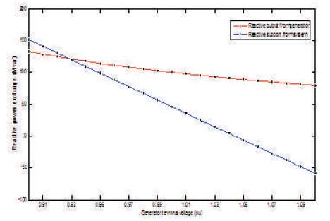
Figure 6. Reactive Power Exchange among Generator Bus and System Bus
With sufficient VAR reserve, the load bus voltage is still maintained at its rated value even though the generator terminal voltage is under low level as illustrated in Figure 7. From the same graph, we can have one more conclusion that the generator should maintain its terminal voltage such that the load bus voltage is at its rated level without any Qsup from system and it is approximately 1.04 p.u. at crossing point.
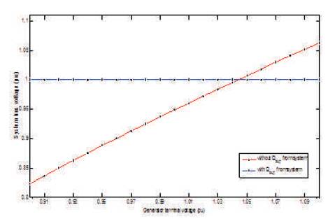
Figure 7. Variation in Load Bus Voltage with a change in Generator Bus Voltage
The same phenomenon in terms of reactive power loss in the system can be observed in Figure 8. The noticeable point is that the minimum loss is incident at a proper voltage level in both the cases. So at this stage, it can be concluded that the maintenance of proper voltage level at source bus is very important while optimizing the transmission loss, reactive power cost as well as voltage stability.
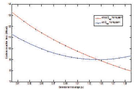
Figure 8. Variation in Sink Bus Voltage with Source Bus Voltage
In loadability problem illustration, the new generation schedule has given more CLM values than base case as well as under all line outage contingencies as illustrated in Figure 3 and this may not be true for other systems. Hence the transmission system loadability as well as voltage stabilities are mainly dependent not only network configuration, but also on generation schedule pattern. This is why the time variant generation schedule in the competitive market scenario should be validated before dispatching in real time by satisfying all system operational constraints. The nature of bidding by market participants is unpredictable in competitive electricity market and hence, it is worthwhile to consider bidding strategies while evaluating static voltage security margin. In generator excitation illustration, various factors related with market economics and security are explained in detail. These examples have shown the need of reactive power optimization towards security enhancement and market economics optimization.
By proper VAR control and support in system, the physical flows can be optimized to result in enhanced system security margins, i.e., Maximum Loading Capability (MLC), Available Transfer Capability (ATC), System Wide Available Transfer Capability (SWATC), and Spinning Reserve (SR). Simultaneously, reactive power costs can be also decreased significantly towards social benefit. In addition to physical and financial flow optimization, the technical benefits, such as to minimize transmission losses and improved voltage profile can be obtained. Due to greater advantages compared with conventional approaches, VAR requirement has been contributed by integrating FACTS devices in the network.