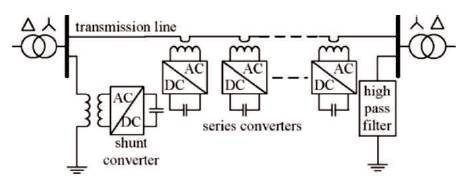
Figure 1. Basic Configuration of DPFC
In recent times, Distributed Power Flow Controller is an important device within the family of FACTS Devices. This paper investigates Multi Level Inverter (MLI) based Distributed Power Flow Controller (DPFC) system for voltage sag mitigation and harmonic reduction. The DPFC employs a Shunt based Static Compensator (STATCOM) and multiple series converters to improve the power quality. DPFC was placed at the correct location in the power transmission system to gain advantages like improved voltage profile and reduced power loss. Circuit models are developed for Eight bus system with and without DPFC. The MATLAB/SIMULINK results obtained shows an improved performance in voltage sag mitigation, voltage quality of load busses, power quality improvement, comparison of the bus voltages with and without DPFC and reduction in load voltage harmonics. The results indicate that MLI based DPFC has improved in power quality and reduction in total harmonic reduction.
The flexible AC transmission system (FACTS) technology is the application of high power devices in transmission systems [1]. The main purpose of this technology is to control and regulate the voltage in the power systems.
This is achieved by using converters as a controllable element between two power systems. The resulting converter representations can be useful for a variety of configurations. Basically, the family of FACTS devices based on Voltage Source Converters (VSCs) consist of a series compensator or a shunt compensator [2]. The static Compensator (STATCOM) is a shunt connected device that is able to provide reactive power support at a network location near load centre. Through this reactive power injection, the STATCOM can regulate the voltage at the receiving end. The Static Synchronous Series Compensator (SSSC) is a series device which injects a voltage in series with the line to compensate the line impedance drop [5] .
Ideally, this injected voltage is in quadrature with the line current, such that the SSSC behaves like an inductor or a capacitor for the purpose of increasing or decreasing the voltage drop across the line. In this operating mode, the SSSC does not interchange any real power with the system in steady state. The Unified Power Flow Controller (UPFC) is the most versatile device of the family of FACTS devices [3], since it can control the active and the reactive power, respectively, as well as the voltage at the connection node. UPFC comprises of a STATCOM and a SSSC coupled via a common DC link to allow bidirectional flow of active power between the series output terminals of the SSSC and the shunt output terminals of the STATCOM. Each converter can independently generate (or) absorb reactive power at its own bus. The two controlled converters are operated from a DC link provided by a DC storage capacitor [3].
The DPFC is able to control all system parameters like line impedance, transmission angle and bus voltage. The DPFC eliminates the common DC wires between the shunt and series converters. The active power exchange between the shunt and the series converter is through the transmission line at the third-harmonic frequency. The series converter of the DPFC employs the distributed FACTS (D-FACTS) concept [6]. Comparing with the UPFC, the DPFC has advantages like Low cost and High reliability because of the redundancy of the series converters and high control capability [10].
FACTS are discussed by Song and John, [1]. Concepts and technology of FACTS are given by L. Gyugyi, and Hingorani, [2]. Concept of UPFC is given by Williams, et al., [3]. Terms and definition of FACTS are given by Edris [4]. Static Synchronous Series Compensator theory is given by K.K. Sen [5]. A Distributed Static Series Compensator system for realizing active power flow control on existing power lines is given by M.D. Deepak, and E.B. Williams [6]. DPFC control during shunt converter failure is given by Y. Zhihui, and B. Ferreira [7].
Similar to the UPFC, the DPFC consists of shunt and series connected converters. The shunt converter is similar to STATCOM, while the series converter employs the Distributed Static Series Compensator (DSSC) concept. Each converter within the DPFC is independent and has its own DC capacitor to provide the required DC voltage. The configuration of the DPFC is shown in Figure 1. The disadvantage of high pass filter is that it requires a high pas filter at the receiving end.
Figure 1. Basic Configuration of DPFC
Within the DPFC, the transmission line presents a common connection between the AC buses of the shunt and the series converters. Therefore, it is possible to exchange active power through the AC buses. The method is based on power theory of non-sinusoidal components. According to the Fourier theorem, complex voltage and current can be expressed as the sum of sinusoidal functions in different frequencies with different amplitudes. The active power resulting from this complex voltage and current is defined as the mean value of the product of voltage and current.
DPFC control during shunt converter failure is given by Y. Zhihui, and B. Ferreira [8]. Utilizing distributed power flow controller for power oscillation damping is given by Y. Zhihui, and B. Ferreira [9]. Modelling and control of utility interactive converters is given by Y. Sozer, and D.A. Torrey [9]. Principle and analysis of the DPFC is given by Zhiyui Yuanand Haan [10]. A Novel Modelling and controlling of Distributed Power Flow Controller (DPFC) based on PSO Algorithm is given by Behrouz Soulat, et al. [11] .
The above mentioned literature does not deal with the modelling and simulation of Eight bus system using five level based DPFC. This work proposes multi-level inverter based DPFC for improving the power quality of eight bus system.
This controller manages all the series and shunt controllers and sends reference signals to both of the shunt and series converters of the DPFC (Figure 2). According to the system requirements, the central control gives corresponding voltage reference signals for the series converters and reactive current signal for the shunt converter. All the reference signals generated by central control are at the power frequency.
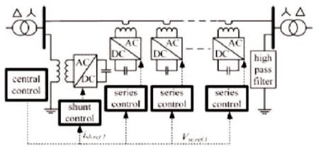
Figure 2. Central Control of DPFC
The circuit of Eight bus system is modelled using the elements available in simulink library of Matlab. This section deals with the simulation results of Eight bus system with and without DPFC.
Eight bus system without DPFC is shown in Figure 3 (a). There are three generator busses and five load busses. An extra load is added at bus 3 to produce voltage sag. One line diagram of eight bus system without DPFC is shown in Figure 3 (b). Each line is represented by a series impedance. The voltage across loads 1 and 2 are shown in Figure 3 (c). The voltage reduces from 5 kv to 4 kv when the additional load is connected at t=0.2 seconds. The real power at bus 3 is shown in Figure 3 (d), and its value is 2 x10⁴ W. The reactive power is shown in Figure 3 (e), and its value is 3700 var. The parameters used for simulation are given in Appendix 1.
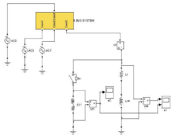
Figure 3 (a). Eight Bus System without DPFC
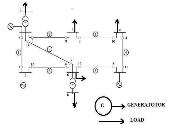
Figure 3 (b). One Line Diagram of Eight Bus System Without DPFC
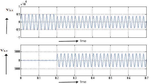
Figure 3 (c). Voltage across Load 1 and Load 2
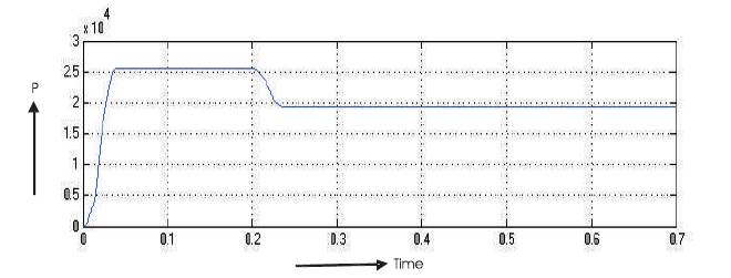
Figure 3 (d). Real Power at Bus-3
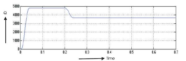
Figure 3 (e). Bus-3 Reactive Power
Eight bus system with DPFC is shown in Figure 4 (a). The one line diagram of eight bus system with DPFC is shown in Figure 4 (b). The voltage across load 1 & load 2 of bus 3 are shown in Figure 4 (c). The voltage of bus 1 is shown in Figure 4 (d). The real power and reactive power at bus 1 are shown in Figures 4 (e), and 4 (f) respectively. The real power is 15 x104 W and reactive power is 3.4 x10⁴ var. The circuit of DPFC is shown in Figure 4 (g). The multilevel inverter used is shown in Figure 4 (h). The output voltage of multilevel inverter is shown in Figure 4 (i). The output voltage has five levels. The voltage at bus 3 is shown in Figure 4 (j). The real and reactive powers at bus 3 are shown in Figures 4 (k) and 4 (l) respectively. The real power is 1.8 x10⁵ W. The reactive power is 4.8 x10⁴ var. The voltage at bus 7 is shown in Figure 4 (m). The voltage at bus 7 increases due to the injection of the voltage by the DPFC. The real and reactive powers at bus 7 are shown in Figures 4 (n) and 4 (o) respectively. The increase in P and Q is due to the increase in the bus voltage. The frequency spectrum for the output of three level inverter is shown in Figure 4 (p). The THD is 5.9%. The frequency spectrum for the output of five level inverter is shown in Figure 4 (q). The THD is 3.5%. Thus the five level inverter injects voltage with minimum harmonic distortion.
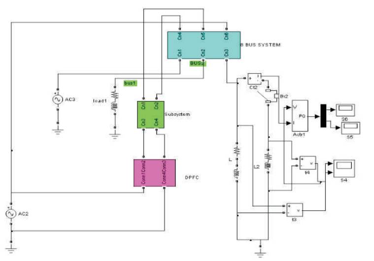
Figure 4 (a). Eight Bus System with DPFC
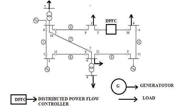
Figure 4 (b). One Line Diagram of Eight Bus System with DPFC
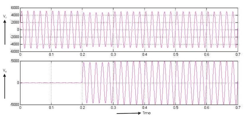
Figure 4 (c). Voltage across Load 1 & Load 2 of Bus 3
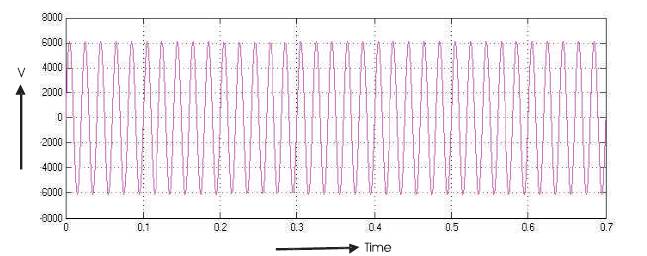
Figure 4 (d). Voltage of Bus 1
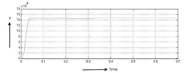
Figure 4 (e). The Real Power at Bus 1
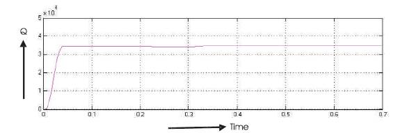
Figure 4 (f). Reactive Power at Bus 1
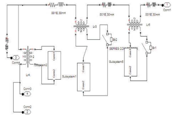
Figure 4 (g). The Circuit of DPFC
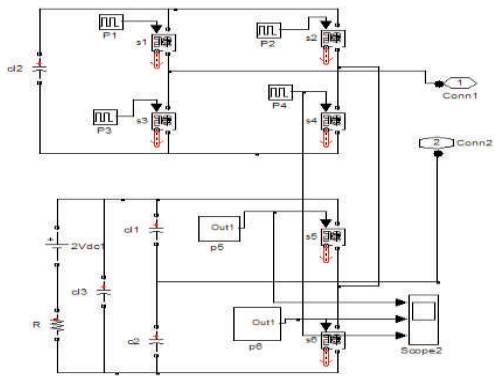
Figure 4 (h). Multi Level Inverter
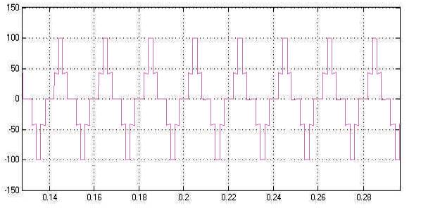
Figure 4 (i). Output Voltage of Multi-level Inverter
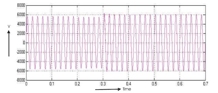
Figure 4 (j). The Voltage at Bus 3
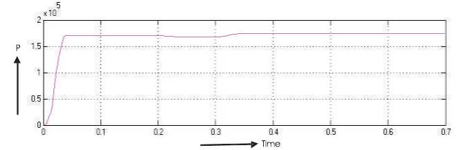
Figure 4 (k). Real Power at Bus 3
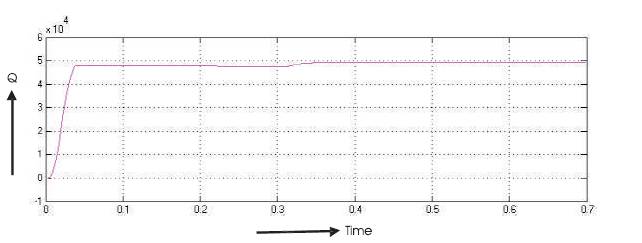
Figure 4 (l). Reactive Power at Bus 3
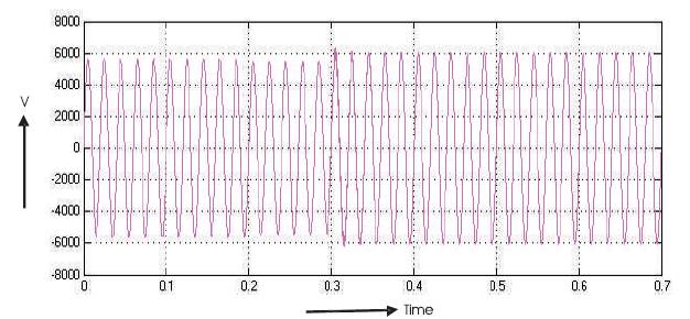
Figure 4 (m). Volatge at Bus 7
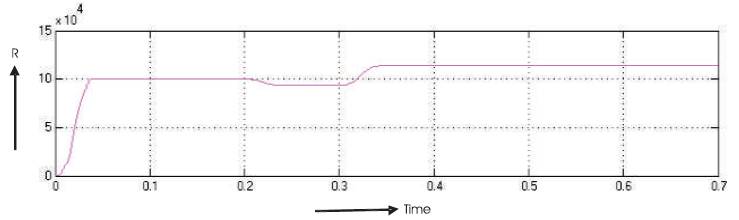
Figure 4 (n). Real Power at Bus 7
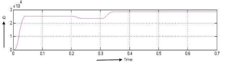
Figure 4 (o). Reactive Power at Bus 7
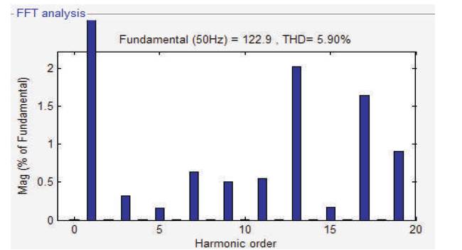
Figure 4 (p). Output of Three Level Multi-level Inverter
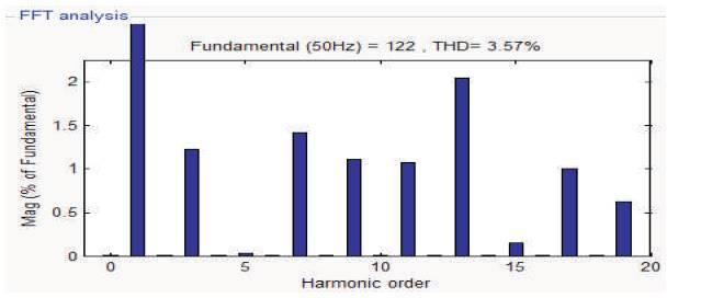
Figure 4 (q). Frequency Spectrum of Five Level Multi- level Inverter
Table 1 gives the comparison of bus voltages with and without DPFC. It can be seen that the bus voltages improve when the DPFC is added. The variation of reactive power with the variation in the shunt injected voltage is shown in Table 2. When the injected voltage increases from 1 kV to 2.5 kV, the reactive power increases from 2.41 to 2.53 Mvar. The variation of real and reactive powers with the variation in the series injected voltage is given Table 3. P and Q increases with the increase in series injected voltage.
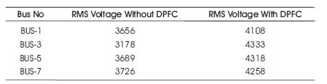
Table 1. Comparision of Bus Volatge with and without DPFC
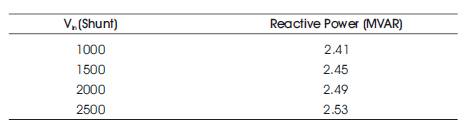
Table 2. Variation of Q with Variation in Shunt Injection
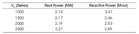
Table 3. Variation of P and Q with Variation in Series Injection
Five level inverter based DPFC is proposed for the power quality improvement in eight bus system. Eight bus systems with and without DPFC are successfully modelled and simulated using Simulink. The results indicate that the voltage quality of load busses were improved by 11% using DPFC. The reactive power was controlled by controlling the magnitude of shunt voltage. The real power was controlled by varying the series injection. The advantage of DPFC is the presence of shunt and series controllers. The disadvantage of DPFC is that it requires through number of series converters. The scope of this work is design, modelling and simulation of eight bus system. This concept can be extended to any higher bus system. The injection will be attempted with higher level type multi level inverter to reduce the THD to a very low value.