[1]
Mitigation and analysis of Very Fast Transient Overvoltages (VFTO) is very important in Gas Insulated Substations (GIS). In this paper, a power transformer rating of 400MVA in 1000kV gas insulated substation has been considered and different techniques for mitigation and analysis of Very Fast Transient Overvoltages (VFTOs) are applied and the outcomes are analyzed by the application of Discrete Wavelet Transform (DWT) as the wavelet transform is superior and a powerful tool for extraction of high frequency transient signals and gives the crisp output. The proposed system has been designed with MatLab platform and the designed system is simulated to evaluate the peak values of Very Fast Transient Overvoltages (VFTOs) generated both at transformer (Vtr) and open end of (Voc) with and without RC – filter, ferrite ring and a nonocrystilline. The results show that the peak value of Very Fast Transient Overvoltages (VFTOs) can be considerably reduced by introducing RC–filter ferrite ring and nanocrystalline methods. The outcomes are explored to wavelet transform for transient information. By the application of wavelet transform, it has concluded that an exact measurement VFTOs can be obtained and is shown in the results.
The power system is large and interconnected one in which the transformer plays an important role and thereby it is very essential to protect it against the internal and external faults as well as from the overvoltages due to any reason, particularly when it is used in gas insulated substation since there is always possibility for continuous likelihood of reason for fast transient overvoltages. Gas Insulation Substations (GIS) have been utilized as a part of force frameworks in the course of the most recent three decades on account of their high unwavering quality, simple support, and small ground space necessity and so on. In India likewise, a couple GIS units are under different phases of establishment. The Basic Insulation Level (BIL) required for a Gas Insulated Substation (GIS) is not the same as that of the traditional substation on account of certain special properties of the previous. Gas Insulated Substation (GIS) has a surge impedance of 70Ω more than that of the traditional oil filled links, however a great deal not as much as that of an overhead line (300Ω - 400Ω). In addition, the GIS is totally enclosed and therefore is free from any atmospheric contamination. Hence, in general the GIS permit lower BIL rating than the conventional one. During switching of disconnectors (DS) in GIS a varying number of pre-strikes and re-strikes occur. Due to the very short duration of the voltage collapse, traveling surges are generated. These Very Fast Transient Overvoltages (VFTO) can become the limiting dielectric stress which defines the dimensions at HV voltage levels [11].
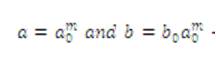
A wavelet is a scientific capacity, which is used to separate a given capacity or constant time signal into various scale segments. Typically, one can allot a recurrence extent to every scale part. Every scale part can then be contemplated with a determination that matches its scale. A wavelet change is the representation of a capacity by wavelets. The wavelets are scaled and deciphered duplicates (known as "girl wavelets") of a limited length or quick rotting wavering waveform (known as the "mother wavelet"). Wavelet changes have favorable circumstances over conventional Fourier changes for speaking to capacities that have discontinuities and sharp tops, and for precisely deconstructing and recreating limited, non-occasional and/or non-stationary signals. Wavelet transform are grouped into Discrete Wavelet Transform (DWTs) and Consistent Wavelet Transform (CWTs). In the wavelet transform, the authors have brought to note that both DWT and CWT are non stationary time (simple) changes. They can be utilized to speak to persistent time (simple) signals. CWTs work over each conceivable scale and interpretation while DWTs utilize a particular subset of scale and interpretation, qualities or representation matrix. There are an expansive number of wavelet changes each suitable for various applications. The wavelet change can be proficient in two unique courses relying upon what data is required out of this change process. The primary technique is a nonstop wavelet change (CWT), where one acquires a surface of wavelet Coefficients, CWT(b,a), for various benefits of scaling "a" and interpretation 'b', and the second is a Discrete Wavelet Transform (DWT), where the scale and interpretation are defamed, however not free variables of the first flag. In the CWT, the variables "a" and "b" are nonstop. DWT results in a limited number of wavelet coefficients relying on the whole number of discretization venture in scale and interpretation, indicated by "m" and 'n'. In the event that are the division step sizes for the scale and interpretation individually, the scale and interpretation regarding these parameters will be,
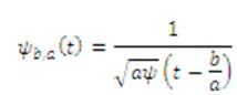
Equations (1) and (2) represent the mother wavelet of persistent time wavelet arrangement. After discretization as far as the parameters,"m" and 'n', the mother wavelet can be composed as,
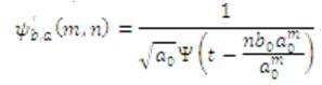
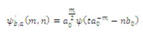
After discretization, the wavelet space coefficients are no more spoken to by a basic "a" and 'b'. Rather, they are spoken to as far as "m" and 'n'. The discrete wavelet coefficients DWT (m, n) are given by the mathematical statement:
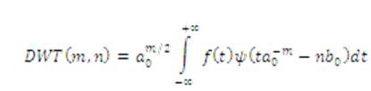
The change is over a consistent time, however the wavelets change over a nonstop time yet the wavelets are assumed to be in a discrete manner. Like the CWT, these discrete wavelet coefficients are the connection between the first flag and wavelet for various blends of "m" and 'n'. In this study, the line current signs are utilized as the data signs of the wavelet examination. The DWT, utilizing a Daubechies-4 wavelet (db4), performed better at recognizing the begin and end of an unsettling influence. The Daubechies (Db) wavelet is extremely appropriate for recognizing brief time, high recurrence homeless people, and in addition low recurrence conduct over longer timeframes. In both cases, the signs are non-occasional or non-stationary. The flaw drifters of the study cases are broke down through discrete wavelet change at levels one to five. Both estimate and points of interest data related to shortcoming current are removed from the first flag with the multi-determination examination.
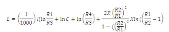
As per the literature survey it has been observed that, the Very Fast Transient Overvoltages (VFTOs) can damp to a considerable level of peak using ferrite rings. Most of the authors [2] tested the ferrite ring under low voltage and low frequency and a conventional comparison is given between the shunt resistor and ferrite ring. This paper presents a new method of analysis of Very Fast Transient Overvoltages VFTOs, which is known as RC-filter along with ferrite ring and nanocrystalline in association with wavelet transform as the VFTOs are concerned to high frequency transients. In this paper, Very Fast Transient Overvoltages (VFTOs) produced by introducing the Disconnecting Switch (DS) [1, 4] has been employed for switching transients in Gas Insulated Substation(GIS). Figure 2 is represented by a PI segment includes two voyaging wave models [4], two capacitors to ground and a capacitor over the softening contacts as shown up Figure1. Disconnector is modeled in different manners [7,8] for open and close positions. In the closed position, it has been modeled as a distributed transmission line. Open position of the Disconnecting Switch (DS) (Figure 2) has been modeled by a series capacitor. In the proposed research work, the power transformer rating of 400MVA, in , 1000kV Gas Insulated Substation (GIS) has been considered and the transformer model is designed with the help of Matlab platform. Since the transformer coil at , high frequencies behaves as capacitive network, the modeling of transformer has been designed based on Very Fast Transients nature (VFT) [7, 8, 9, 10] i.e, the parameters of a transformer are estimated for accurate simulation results and are given by, R1 = 20.5 Ω , R2 =22.5 Ω,R3 =300 Ω and inductance of the coils L1 = 4.02 μH, L2 = 35.5 μH , L3 = 7.37 μH and the capacitance C1 = 0.77 pF, C2 = 1.26 pf, C3 = 33.8 pF, C4 = 940pF, the surge impedance, velocity of propagation, formative time and length are considered as well as the series capacitance between the turn and coil and the shunt capacitance between the turn [6], coil and grounded core and transformer tank are considered for accurate results of the peak magnitude of Very Fast Transient Overvoltages (VFTOs). The parameters of power transformer is estimated as per the Very Fast Transient nature (VFT) for accurate measurement of Very Fast Transient Overvoltages (VFTOs) [5, 8, 1]. The surge impedance (z), propagation velocity (υ) and formative time (τ) can be evaluated from the equations (6), (7) and (8).
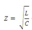
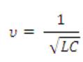
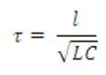
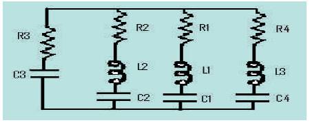
Figure 1. Equivalent Circuit of Power Transformer
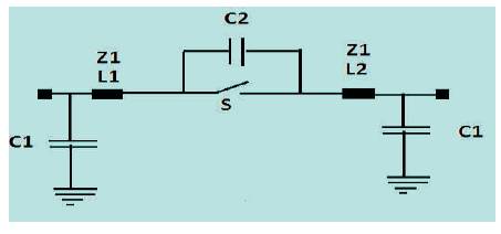
Figure 2. Equivalent Circuit of Disconnecting Switch (DS)
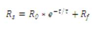
In this work, Disconnecting Switch (DS) [1, 4] (Figure 2) has been employed for switching transients and it is designed as per open and closed conditions. During the closing operation of Disconnecting Switch (DS), the electric field increases still sparking occurs and the sparking occurs at the power frequency first. During the closing operation of the Disconnecting Switch (DS) the charging current flows and charge the load to the source voltage and voltage collapses and extinguishes [5, 7]. The sparking charge depends on the speed of the Disconnecting Switch (DS). The Disconnecting Switch (DS) is represented to by a PIsection that contains two travelling wave models, two capacitors to ground and a capacitor across the contacts as shown in Figure 2 with the parameters as Z1 =35 Ω, L1 = 640mH, L2 =450mH, C1 =25pF and C2 =2.5 pF. The sparkle utilized as a part of Disconnecting Switch (DS) re-strike cases is displayed as an exponentially rotting resistance Ro e(-t/τ) in arrangement with a little resistance, r of 0.5 Ω to deal with the lingering flash resistance. Value of fixed resistance rs has been selected on the basis of the practical consideration as discussed.
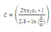
where, R0 = 106MΩ, Fixed Resistance =0.5Ω. T (spark time constant) =1 ns, Open end section of GIS - The open ended section of GIS has been presented in the following figure, where a lumped shunt capacitance has been considered. Assuming the same as a coaxial hemisphere, its capacitance has been estimated using the following equation.
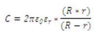
Where, R= internal radius of enclosure, and r=external radius of enclosure.
The Disconnecting Switch (DS) can be modeled either as open end or closed end. In this paper, the closed Disconnecting Switches (DS) are modeled as a transmission line with distributed parameters. The capacitance of the switching contacts towards the ground is considered. For open condition of switching the Disconnecting Switches (DS) are represented with an inter electrode capacitance of the switching contacts towards the ground is considered.
Initially in this research work, the proposed system has been simulated without any damping and without wavelet transform and the simulation outcomes are shown in Figure 3 and Figure 4.
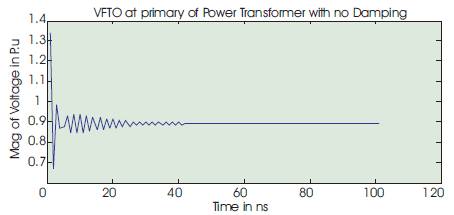
Figure 3. VFTO at Transformer without Damping
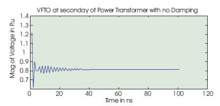
Figure 4. VFTO at open end without damping
From Figures 3 and 4, the peak magnitudes of Very Fast Transient Overvoltages (VFTOs) can be observed. The peak magnitude of VFTO at transformer is 1.324 p.u and at the open end is 1.204 p.u. The outcomes of the simulation results has been explored to the wavelet transform and the transient signals are extracted for transient information and the Very Fast Transient Overvoltages (VFTOs) are again evaluated with wavelet transform, Figure 5 and Figure 6 show the simulation results of the wavelet transform.
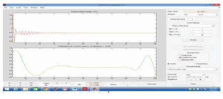
Figure 5. VFTO at Transformer without Damping
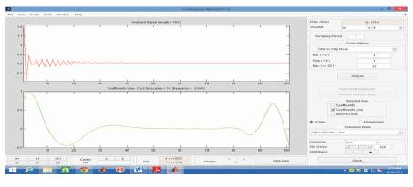
Figure 6. VFTO open end without Damping
The simulation outcomes by the wavelet transform, the evaluated magnitude of VFTO at the transformer is 1.448 p.u and at the open end it is 1.33p.u. Table 1 shows the magnitude of VFTOs at the transformer and at the open end along with the error in magnitude of the Very Fast Transient Overvoltages (VFTOs) with and without wavelet transform.
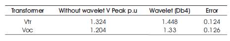
Table 1. Voltage peak without Damping p.u
In the next stage of the research work, the ferrite ring has been used as a damping device Most of the authors [1, 3, 4] have tested the ferrite ring under low voltage and low frequency and conventional comparison is given between the shunt resistor and ferrite ring. As per the literature survey [3. 5, 12], it has been observed that, the Very Fast Transient Overvoltages (VFTOs) can damp to a great considerable level of peak using ferrite rings. The most of the authors have tested the ferrite ring under low voltage and low frequency and conventional comparison was given between the shunt resistor and ferrite ring. This paper introduced a new method of analysis of Very Fast Transient Overvoltages (VFTOs) which is known as wavelet transform as they are concerned to high frequency transients. The comparable circuit of ferrite ring is shown in Figure 3.
In Figure 7, the parameters of the ferrite ring used as R = 100 ohm and L = 2H and the switching time is 10 ms. The proposed system is again simulated with ferrite ring and the simulation results are extracted. Figure 7 and Figure 8 show the simulation results of the proposed system with a ferrite ring both at the transformer (Vtr) and open end (Voc) without wavelet transform.
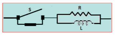
Figure 7. Equivalent Circuit of Ferrite Ring
From Figures 8 and 9 the peak magnitudes of VFTOs can be observed. The peak magnitude of VFTO at transformer (Vtr) is 1.028 p.u and at the open end (Voc) is 0.965 p.u. The outcomes of the simulation has been explored to the wavelet transform and the transient signals are extracted for transient information and the VFTOs are again evaluated with the wavelet transform, Figure 10 and Figure 11 show the simulation results by the wavelet transform.
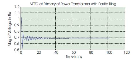
Figure 8. VFTO at Transformer with Ferrite Ring
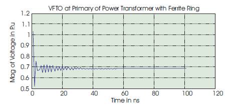
Figure 9. VFTO at Open End of with Ferrite Ring
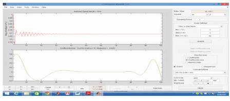
Figure 10. VFTO at Transformer with Ferrite Ring
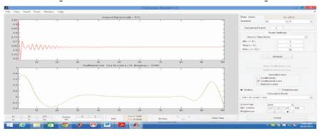
Figure 11. VFTO at open end with Ferrite Ring
The simulation outcomes by the wavelet transform, the evaluated magnitude of VFTO at the transformer is 1.012 p.u and at the open end it is 1.015 p.u. Table 2 shows the magnitude of VFTOs at the transformer (Vtr) and at the open end (Voc) along with error in VFTOs.
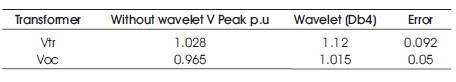
Table 2. VFTO with Ferrite Ring in p.u
In the further stage of the research work, The RC- filter has been considered for mitigation and analysis of VFTOs at the transformer (Vtr) as well as at the open end (Voc). The RC channel has been associated in parallel with the Disconnecting Switch (DS). The optimal qualities decided for R=100 Ω and C =0.2μF, sine the capacitor ingests the high recurrence parts, the greatness of voltage and steepness falls quickly, due to this character of capacitor, it has been executed as one of the strategy for mitigation and analysis.
Figure 13 and Figure 14 show the simulation results of magnitude of VFTOs at transformer and at the open end of the proposed system with RC – Filter without the wavelet transform. From the simulation results, the magnitude of VFTOs at transformer (Vtr) and at open end (Voc) can be observed as 1.0122 p.u and 0.75 p.u
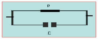
Figure 12. Equivelent circuit of RC- Filter
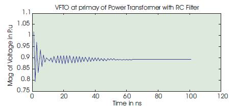
Figure 13. VFTO at transformer with RC filter
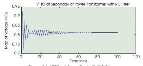
Figure 14. VFTO at Open End with RC Filter
The outcomes of the simulation results has been explored to the wavelet transform and the transient signals are extracted for transient information and the VFTOs are again evaluated with the wavelet transform, Figure 15 and Figure 16 show the simulation results by the wavelet transform.
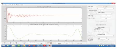
Figure 15. VFTO at Transformer with RC filter
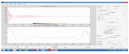
Figure 16. V VFTO at open end with RC filter
The simulation outcomes by the wavelet transform, the evaluated magnitude of VFTO at the transformer (Vtr) is 1.125 p.u and at the open end (Voc) it is 0.798 p.u. Table 3 shows the magnitude of VFTOs in p.u at the transformer (Vtr) and at the open end (Voc) along with error in VFTOs when the simulation is carried with and without the wavelet transform.
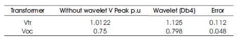
Table 3. VFTO with RC filter
In the next stage of this research work, the combination of both RC – Filter and Ferrite - ring has been employed for mitigation and analysis of VFTOs at transformer (Vtr) as well as at the open end (Voc). Figure 17 and Figure 18 show the simulation results of the proposed method. From the simulation results, the peak magnitude of VFTOs are evaluated at transformer (Vtr) as well as at the open end (Voc) as 0.768 p.u and 0.7245 p.u respectively.
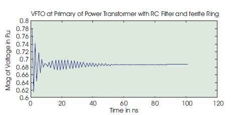
Figure 17. VFTO at transformer with RC Filter and Ferrite Ring
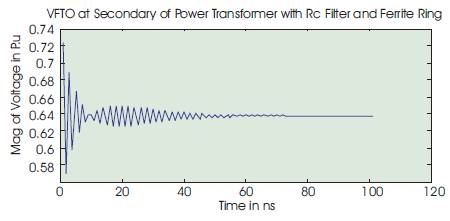
Figure 18. VFTO at Open End with RC Filter and Ferrite Ring
The simulation results again explored to the wavelet transform for extraction of high frequency transient signals and the peak magnitudes of VFTOs at transformer (Vtr) and at open end (Voc) are evaluated. Figure 19 and Figure 20 show the outcomes of the wavelet transform.
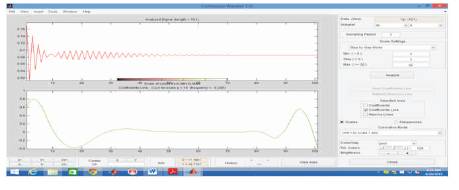
Figure 19. VFTO Peak at Transformer with RC Filter and Ferrite Ring
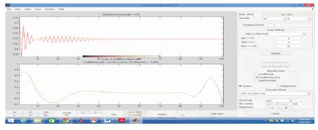
Figure 20. VFTO at Open End with RC Filter and Ferrite Ring
The simulation outcomes by the wavelet transform, the evaluated magnitude of VFTO at the transformer is 0.9178 p.u and at the open end it is 0.9186 p.u. Table 4 shows the magnitude of VFTOs in per unit at the transformer (Vtr) and at the open end (Voc) along with error in VFTOs when the simulation is carried with and without wavelet transform.
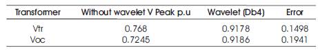
Table 4. VFTO with RC Filter and Ferrite Ring
In the further stage of this research work, the combination of RC- Filter, Ferrite Ring and nanocrystalline has been employed in the proposed system for mitigation and analysis of VFTOs at transformer and at the open end. Since nanocrystalline exhibits enhanced electrical property in the high frequency range (100 KHz to 3 MHz) they have high dielectric strength. The nano crystalline is modeled as R, L connected in series and connected in parallel with capacitor. The parameters are evaluated as per the VFT nature of switching transients, parameters are R= 150Ω, L=0.002mH and C = 0.001nF chosen in the design of nanocrystalline. Figure 21 shows the equivalent circuit of nanocrystalline employed in the proposed system.
Figure 21. Equivalent Circuit of Nanocrystalline
Figure 22 and Figure 23 shows the simulation results of the proposed method. From the results, the magnitude of VFTO at transformer (Vtr) and at open end (Voc) are evaluated as 0.2695 p.u and 0.250 p.u respectively.
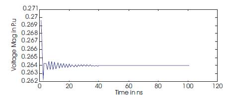
Figure 22. VFTO at Transformer with RC Filter, Ferrite Ring and Nanocrystalline
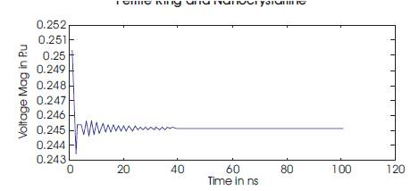
Figure 23. VFTO at Open End with RC Filter, Ferrite Ring and Nano Crystalline
The simulation results again explored to the wavelet transform for extraction of high frequency transient signals and the peak magnitudes of VFTOs at transformer (Vtr) and at open end (Voc) are evaluated. Figure 24 and Figure 25 show the outcomes of the wavelet transform.

Figure 24. VFTO at Transformer with RC Filter, Ferrite Ring and Nanocrystalline
Figure 25. VFTO at Open End with RC Filter, Ferrite Ring and Nanocrystalline
The simulation outcomes by the wavelet transform, the evaluated magnitude of VFTO at the transformer is 0.0005 p.u and at the open end it is 0.001p.u. Table 5 shows the magnitude of VFTOs in per unit at the transformer and at the open end along with error in VFTOs when the simulation is carried with and without the wavelet transform.
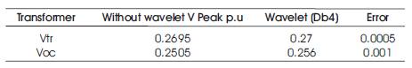
Table 5. VFTO with RC Filter, Ferrite Ring and Nanocrystalline
In this exploration work, the power transformer of rating 400MVA, in 1000kV in Gas Protected Substation (GIS) has been viewed as and is planned MatLab stage. The parameters of the proposed framework have been planned by taking after the quick transient nature (VFT). The crest extent of quick transient Overvoltages (VFTOs) at the transformer and at the open end have been assessed with and without damping gadgets like ferrite ring, RC channel and nanocrystalline and in the blend of the damping gadgets additionally utilized. The greatness of VFTO at transformer (Vtr) with no damping is 1.324 p.u and at the open end it is 1.204 p.u.
The results have been investigated by the wavelet transform and it has been founded that the VFTO at transformer (Vtr) is 1.448 p.u and 1.33 p.u separately and is appeared in Table 1. In the following stage the proposed framework has been utilized with ferrite ring and the reproduction work has been conveyed and the VFTO at transformer (Vtr) is decreased to 1.028 pu and at open end it is diminished to 0.965 p.u and with wavelet change VFTOs at transformer (Vtr) is 1.12 p.u and at open end it is 1.015 p.u and is appeared in Table 2. In the following phase of this work, RC channel has been utilized and the reenactment work has been proceeded for the estimation of VFTOs at the transformer and open end. With RC channel, the greatness of VFTO at transformer (Vtr) is 1.0112 p.u and at opened it is 0.75 p.u and in addition with wavelet changes it is found that 1.125 p.u and 0.798 p.u separately appeared in Table 3. In the same grouping, the recreation work has been conveyed for the estimation of VFTOs at transformer and open end with and without the wavelet change and the results has been appeared from Table 4 and Table 5.
From the outcomes, the following were observed