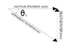
Figure 1. Power Triangle
This paper presents the design and implementation of capacitor banks to improve the performance of captive generation in petrochemical industry. Now-a-days many industries faces the problem of maintaining power quality during scheduled power outages. While transferring the load from utility supply to the captive generation supply, facing the problem of voltage dip due to heavy loading condition, affects the system performance. In order to overcome this problem, situation was analyzed and suggested to install capacitor banks at the generator feeder to improve the system performance. Power World simulator is used to analyze the problem and to observe the performance of the system after the installation of the capacitors. The case study of petrochemical industry has been taken to identify the actual problem analysis and its solution.
Industrial process is the one where the work will be carried out whole day and whole year. As the system will be working without any rest, the power system will be facing problem due to some loading condition. As the loads in the industries will be varying as when, the generating units and other loads are facing a problem of power factor (pf) in the system. And the increased use of the non-linear loads such as PCs', Xerox machines and other electronic devices has also created a lot of problem in the system by generating harmonics by which systems have become less efficient. In order to overcome all these, p.f. correction using capacitors are suggested. All the ratings are calculated using Indian Standard and the harmonic analysis are done using energy and harmonic analyzer. Using this analyzer, all the analysis has been carried out. And the harmonics are measured as per IEEE 519-1992 standards. The required MVA is calculated using power triangle. The actual system is represented in Power World simulator software and then the case study system is simulated in that software for present condition. The Power World simulator is the software where the entire power system component is available and can be used to analyze the system in the required condition. In [2] the paper has clearly explained how present trend is working on passive filters as well as the power factor correction. Now-a-days the difference between passive filter and the power factor correction is not that much. In [1] pf correction using the diode rectifiers has been explained. In [3]the hybrid solution where the system can act as both passive filter and pf corrector is done. [4] The designing of filter has been explained. [5] The Power factor correction for non-linear loads has been explained using rule based modulated passive filter technique. It [6] has explained the solution for source voltage unbalance/current harmonic compensation and power factor correction using unified active filters. [7] [8] The text book which explains the operation of the system and basic concept on the reactive power compensation and power quality problems.
During scheduled outages transferring the load from utility supply system to the captive generation supply, the problem facing the voltage dip due to heavy loading condition will affect system performance. When the loading condition vary in the system, particularly when the load is raised from base load to the peak load, it has seen the voltage will dip until the required voltage is not in the range. This in turn will affect the generator working, getting heated up and losses are more, meanwhile the power factor at the time of load increases from base load to peak load is lower than the limit. Hence the system is said to be facing a problem of power quality.
As we all know, capacitor is one which gives a leading power factor by delivering a reactive power to the system. The load is the one which gives an inductive effect in the system. The p.f. in the actual system is lagging due to these kinds of loads. In the distribution system when the loads are switched on, lot of reactive power are taken by the loads, and hence during that time the p.f. will be low. If the p.f. is low, then the generators will face the problem such as the required magnetizing current may not be maintained, hence the generator will afford to maintain the required magnetizing current and the result will be the increased losses in the system. Where as in industries, if p.f. is lower than the limit, electricity board will penalize the industry. Hence, in most of the industries, the p.f. is improved using reactive power sources. Before installing the capacitor banks in the industries, the audit is carried out and the whole system is checked for the requirement of reactive power. If the industries are having a large capacity machine than it is suggested to install the capacitor banks wherever required, and to avoid the other part of the system to face the problem. If the required feeder is showing the p.f. within the limits than no requirement of installing the capacitor banks in the individual feeder, it is enough to install in the main feeder.
The calculation of the reactive power is carried out using power triangle. The description of the power triangle is shown Figure 1.
Figure 1. Power Triangle
Figure 1 is the power triangle from which the required reactive power is calculated. If the p.f. angle θ is lagging 1 than the reactive power, it has to be adjusted in such a manner that the p.f. is improved. The corrected p.f. calculation is shown in Figure 2.
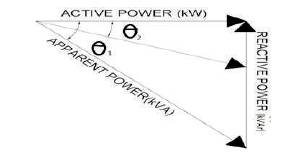
Figure 2. Final Power Triangle to improve p.f.
Thus the p.f. can be improved by adjusting the p.f. angle to θ2 , and calculating the required reactive power to that angle. And the obtained reactive power is installed in the system so that, the p.f. is improved. Since the capacitor are sensitive to the harmonics and the other unwanted things, it becomes necessary to provide the detuned reactor as per the standard, so that it will filter the unwanted things and make the capacitor to work properly in a safe manner, and the life of the capacitor will increase.
The single line diagram of petrochemical industry is shown in Figure 3. The present condition in the petrochemical industry is having an 110kV supply from the grid. This 110kV supply further steps down to 6.6kV through 6.6kV, 20/25MVA step down transformer. Thus six transformers are connected there to six different feeders.
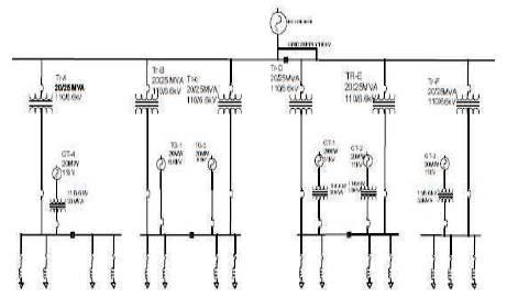
Figure 3. Single Line Diagram of Petrochemical Industry
Each transformer is named Tr-A upto Tr- F, and to each feeder, each generator is connected. Feeder voltage is maintained as 6.6kV. Four generators are having a rating of 20MW, 11kV at Tr-A, Tr-d, Tr-E and Tr-F, and two generators are having a rating of 6.6kV, 20MW at Tr-B and Tr-C. Four generators are named GT-1 to GT-4 and remaining two as TG-1 and TG-2. These four generators are connected to feeder through 11/6.6kV step-down transformer. Tr-B, Tr-C and Tr-E, Tr-F are connected to each other through bus coupler. The whole system is synchronized. The generated power can be transferred from one system to other.
There are different ways of compensation used in a practical system. They are shown in Figure 4 and are explained below.
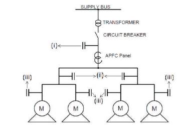
Figure 4. Compensation
When the reactive power requirement is more at the main supply, then central compensation is usually chosen. Central compensation is mainly connected in the main boards of the system where supply from utility will be there. While giving compensation at the central, the requirement of reactive power for the whole system is analysed and the required value of the reactive power is chosen. The connection to the main supply is given as per the demand.
This kind of compensation is given when a group of load is involved. In industries, there will be separate feeders for separate department. There will be separate transformer connection for each department. In this condition, the variation in one department should not affect the other department. Keeping this in mind, the requirement of reactive power at each department is analysed, if the reactive power requirement is ver y high then compensation for that department is given to the feeder of that department. This kind of compensation is called as Group Compensation.
As in industries, the induction motors are used in large numbers. As induction motors take large number of the reactive power, the magnetising current and all other factors will affect the other systems connected to it, even it affects the transformer connected to it. If compensation is not given to these motors, lot of damages may occur in the system. In order to overcome all this, individual compensation is given to each induction motor in the industries. This kind of compensation will manage variation of reactive power in the induction motor.
In this kind of compensation, requirement of reactive power is constant. This kind of compensation is chosen only when the constant load is there and fixed amount of reactive power has to be supplied. This compensation involves manual switch on and off. The operator in the industry, analyze the requirement of reactive, and how much reactive power has to be supplied according to that they will switch on the capacitor bank. This process requires lot of maintenance and also as fault happens, lot of damage occurs. Usually in industry when certain motors are to be operated, then this type of compensation is good. This compensation basically involves group compensation, where group of load will be switched on and takes constant power for several hours.
These type of compensation is the one in which the banks will switch on and switch off automatically. The system which uses this kind of compensation is usually called as Automatic Power Factor Correction (APFC) panels. These types of compensation are usually used in the Group Compensation as well as Central Compensation. These APFC's usually have a Microprocessor (P) or Microcontroller (C) relays which act like brain of the panels. These relays will obtain the signals from the system and according to those signals, they will switch on or switch off the banks. In industries, the load will vary as per the required condition, the current which flows to the main bus bar in the panels will send the signals to the P or C through the Current Transformer (CT), as all the three main bus bars will be having individual CT's connected to it.
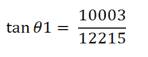
At the time of voltage dip when gaining load i.e., from base load to peak load,
Active power = 12215kW
Reactive power = 10003kVAR
pf = cosθ1 = 0.7752
In order for compensation, using the power triangle, if the reactive power of 5695.94kVAR is used then the p.f. will increase to 0.906.
At base load,
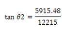
If the new value of θ2 is used to get a pf of 0.95, then the value of θ2 should be 18.19°. Then the tan value can be iven as,
pf = cos θ2 =0.95, which implies that, if a reactive power of 5991.27 MVAR is provided from external source than the p.f. will be improved to 0.95.
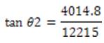
If the required p.f. is about 0.9, then θ=25.84°
This implies that if reactive power of 4089.51 MVAR is provided from external source, then the p.f. will be improved to 0.9.
When the problem was taken for analysis, number of factors was taken into account. The analysis is done using power world simulator for actual condition of the system. The simulation model is shown in Figure 5.
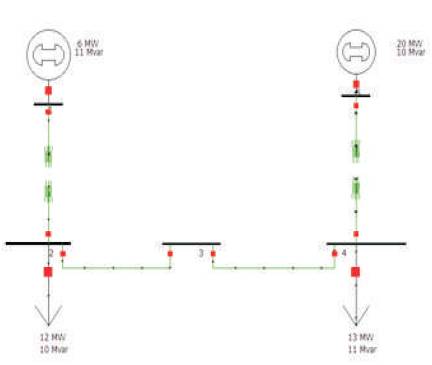
Figure 5. Simulation Model for Actual Condition
After simulating the system, when result of the voltage was seen, it showed a voltage dip below a standard range at feeder 2, 3 & 4. The result of voltage dip is shown in Figure 6.
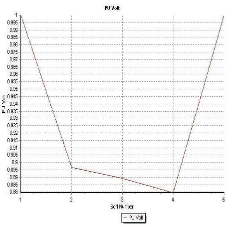
Figure 6. Simulation Result of Voltage
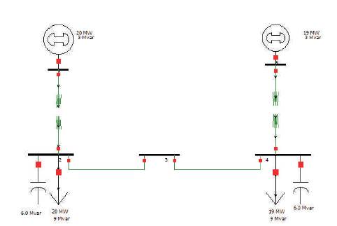
Figure 7. Simulation model after installation of capacitors
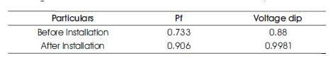
Table 1. Value of Voltage Dip and PF
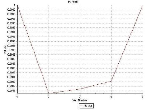
Figure 8. Simulation Result After Installation of Capacitors
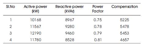
Table 2. Compensation at Different pf
It has been found out that these capacitors are provided in the panels. So, the cost for 1MVAR was found to be 7.5 lakh. Thus, the overall cost for single 6MVAR panel is 45lakh. It has been observed that, if the static VAR compensator was chosen for providing reactive power source, then cost have been more than this, and it is economically affordable to use the capacitor for these kind of problems.
The paper presents an analysis and proper solution to power quality problems during scheduled outages in Petrochemical Industry. Actual problem is identified while switching the load from utility supply system to the captive supply system. The voltage dip problem is analyzed and suggested to install the capacitors to overcome the power quality problem and hence to improve the system performance.