[1]
Electrical power systems usually cover large geographical areas and transmission facilities, that are incessantly increasing. These power systems when exposed to different environmental conditions may cause severe faults to occur on the existing system. In this paper, the need for transposing the lines for analysing the faults under phase and sequence frame of reference has been described. Currents flowing in any one conductor will induce voltage drops in the other successive conductors and these may be unequal even though the currents are balanced which is highly objectionable. In order to minimize the effect of line unbalance, there is a chance of interchanging the conductor positions at their regular intervals along the line, termed Transposition. The objective of this paper is to show the effect of transpositions in producing equal series self and mutual impedances in the phase and sequence frame of reference for a chosen 400 kV, double circuit, single ground wire tower configuration. It is also shown that, by applying nine transpositions technique, the effect of mutual sequence coupling between the two circuits is eliminated completely and balanced phase impedance matrix of 6X6 is obtained. The calculations of overhead lines for different tower configurations was carried out using digital computer program MATLAB and results obtained conventionally shows an excellent resemblance in obtaining balanced phase and sequence impedance matrices. Thus, the same simulation can be used for any tower configuration.
In practice, overhead transmission line is a intricate arrangement of conductors all of which are mutually coupled not only to each other but also to earth. The mutual coupling is both electromagnetic and electrostatic. The asymmetrical positions of the phase conductors with respect to each other, the earth wires and/or the surface of the earth causes some unbalance in the phase impedances, and hence currents and voltages. This is detrimental and in order to minimise the effect of line unbalance, it is likely to interchange the conductor positions at regular intervals along the line route which is a regular practice known as transposition [1]. The aim of this is to achieve some averaging of line parameters and hence balance for each phase.
The days of hand or analytical calculations of overhead line phase and sequence impedances have extensively gone together with, unfortunately, some of the great distant such methods were provided. The calculations of overhead line and cable electrical parameters at power frequency, i.e. 50 or 60 Hz, as well as higher frequencies, are nowadays efficiently carried out using digital computer programs [6]. As well, few necessary tools were presented in [8], which provided the transmission line owners to make an educated decision on transmission line transposition.
In present scenario, electricity has matted itself into the very heart and veins of the society. The performance of a power system mainly depends on the performance of the transmission system for which continuous operation of transmission lines without sudden outages are important for its performance in the view point of power delivery as well as system stability [2]. Measurement of overhead lines power frequency electrical parameters like self and mutual impedances which can be made at the time of commissioning when the line construction has been completed, that the tests replicate the line in normal service operation. The impedance matrices are constructed and then the sequence impedances are calculated for different transpositions. Modern computer technology gives a prospect to prevent the difficulties occurred during the calculation of unbalance caused by transmission lines as well as to implement the new approach in relation to operational speed and accuracy of calculations [7].
Bundled conductors are used for 220kV and above overhead lines with two, three, four, six and eight conductor bundles per phase. These are used to reduce the voltage gradients at the surface of the conductor, reduce corona loss and to reduce radio interference. Quad bundled Phase conductors are chosen for 400kV tower configuration [1].
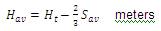
The average sag is taken for phase conductors and earth wires, between towers together with the height of the conductor at the tower and can be used to calculate an average conductor height for the use in calculation of line's electrical parameters. For span lengths of 400 to 500m, [1] derived by assuming that the variation of conductor height with distance between the towers is a parabola, i.e.
where, Hav is the average Height in m
Ht is the total Height in m
Sav is the average sag in m
A line is a static power plant that has electrical parameters distributed all along its length. The basic parameters of the line are conductor series impedance and shunt admittance. Each conductor has a self-impedance and there is mutual impedance between any two conductors and impedance generally consists of a resistance and a reactance.
Considering a 400kV, double circuit line with a near vertical phase conductor configuration and one earth wire is shown in Figure 1.
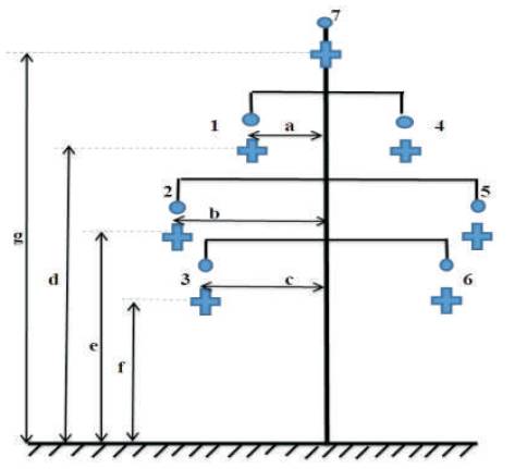
Figure 1. 400 kV D/C, 1 - GW
The conductors are numbered as 1-7 and their spacing's include average conductor sag relative to the centre of the tower and earth. The self impedance of every individual conductor and ground wire is given as,
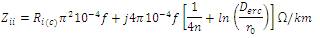
and the mutual impedances between the conductors 'i' & 'j' is given as,
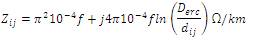
and these depends on the physical spacings of the conductor. Using above two equations (1) and (2), the 7X7 full phase impedance matrix for 400kV; 1-GW is obtained as shown below in Matrix 1.
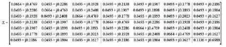
Matrix 1. Full 7x7 Phase Impedance Matrix
In large scale Power system SC analysis, the authors are interested in the calculation of short circuit currents on the faulted phases R,Y,B or combination of these but generally not in the currents flowing in earth wires. The mathematical elimination of the earth wire only eliminates their presence from the full matrix, but not their effects which are included in the modified elements of the reduced matrix.
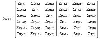
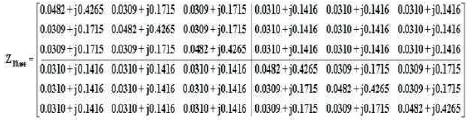
Thus the Full Phase Impedance Matrix 'Z' reduced to the Phase Impedance Matrix 'ZPhase' which results in 6X6 matrix as shown above. Hence the reduced impedance matrix in phase frame of reference is obtained in Matrix 2.
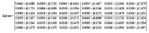
Matrix 2. Reduced 6x6 Phase Impedance Matrix
In the above matrix 2, the diagonal elements are the selfimpedances of each phase and the off-diagonal elements are the mutual impedances between the phases of same circuit and adjacent circuit where each impedance is the actual physical element. The above matrix contains unbalanced impedances and also intersequence mutual couplings, the self impedances of each circuit of A and B and the mutual impedances between two circuits AB and BA are not balanced within themselves, thus shows the necessity for transposition of lines.
The corresponding sequence impedance matrix for similar phasing (RYB/RYB) of two circuits obtained by transforming the phase impedance matrix is shown below in Matrix 3.
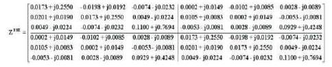
Matrix 3. Sequence Impedance Matrix for Similar Phasing
This sequence impedance matrix is full and non-diagonal which shows that, there exists mutual coupling between the sequence circuits. To eliminate mutual couplings, the sequence impedance matrix has to be made diagonal. The corresponding sequence impedance Matrix 2, for circular phasing (RYB/RYB) of two circuits is calculated by using equation 4.
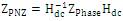
where Hdc is the transformation matrix for a double- circuit line for RYB/BYR Phasing given by,
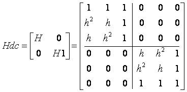
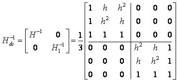
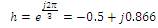
where h is the operator.
The obtained sequence matrix, as shown in Matrix 4 has full inter sequence mutual coupling, and it is encouraged to eliminate the mutual couplings between them i.e. to make the off diagonal elements to zero.
Matrix 4. Sequence Impedance Matrix for Circular Phasing
To eliminate the inter sequence mutual couplings, the line is to be perfectly transposed. Perfect phase transposition means that, each phase conductor occupies successively the same physical positions as the other two conductors in two successive line sections [4]. The authors assume the length of the sections as equal.
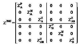
Let us designate t1(top), m1(middle) and b1(bottom) as conductor positions of circuit A, and t2, m2, and b2 as conductor positions for circuit B. Circuit A and B phased RYB, A and B underwent forward phase transpositions (both circuits have RYB Phasing) with three sections having equal length as shown in Figure 2.
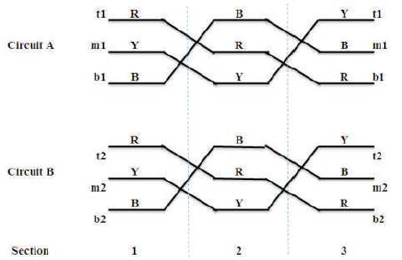
Figure 2. D/C Line with Three Transpositions
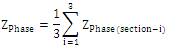
The series phase impedance matrix of the double-circuit line with the three-phase transpositions is given by,
where,
In the below inter-circuit mutual impedance matrix, the self or diagonal terms are not equal, but the off-diagonal terms ZM(AB) and ZN(AB) are not equal resulting in an unbalanced matrix, and it can be made balanced if the off-diagonal terms ZM(AB) and ZN(AB) can be changed to ZM (AB) + ZN(AB) as shown in Matrix 5. And this can be achieved by using further three transpositions i.e. a total of six transpositions, as shown in Matrix 6.
Matrix 5. Series Phase Impedance Matrix
Matrix 6. Phase Impedance Matrix
The average self-phase impedance matrix of circuit A and circuit B per-unit length are same, but in the inter- circuit mutual impedance matrix, the diagonal terms and off-diagonal terms are not equal resulting in an unbalanced matrix.
In the obtained sequence impedance matrix, the positive and negative sequence components are present in the inter-circuit mutual impedance matrix as shown in Matrix 7.
Matrix 7. Sequence Impedance Matrix
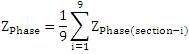
For circular phasing, Circuit A is phased RYB and B is phased BYR, the transpositions with six sections are shown in Figure 3.
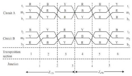
Figure 3. D/C line with Six Phase Transpositions
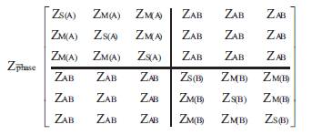
The 6x6 series phase impedance matrices per unit length of double circuit line with the six transpositions is given in Matrix 8 using the equation given below.
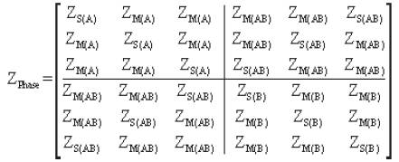
Matrix 8. Series Phase Impedance Matrix with Six Transpositions
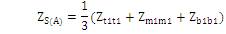
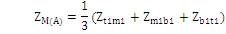
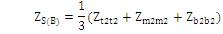
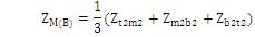
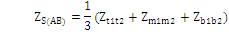
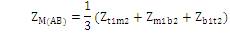
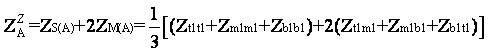
where ZS(A) , ZM(A) , ZS(B) , ZM(B) , ZS(AB) are obtained as (14), (15), (16), (17) and (18) respectively.

where,


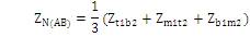
Inter circuit mutual sequence matrix still contains inter sequence mutual couplings which can be eliminated by doing further three transpositions i.e., total of nine [3].
With the use of six transpositions, the effect of mutual sequence coupling between the two circuits is not entirely eliminated with like sequence coupling between the two circuits remaining and this may indeed be the desired result [5]. However, if required, it is even possible to eliminate the Positive Sequence Impedance (PPS) and Negative Sequence Impedance (NPS) coupling and retain Zero Sequence Impedance (ZPS) coupling only between the two circuits. Because there are two three phase circuits of conductors, each phase conductor has to be transposed within its circuit and with respect to the parallel circuit.
In other words, if one circuit is subjected to three transpositions, then for each one of its sections, the other circuit should undergo full three section transpositions. This produces a total of nine transpositions for our double-circuit line.
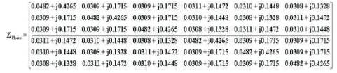
It can be shown analytically by inspection or by matrix analysis that the effect of this nine transposition assumption is to produce the following 6×6 phase impedance matrix.
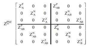
Matrix 9. Sequence Impedance Matrix
Matrix 10. Phase Impedance Matrix
Matrix 11. Sequence Impedance matrix
Matrix 12. Series Phase Impedance Matrix with Ideal Nine Transpositions
Below Figure 4, shows double circuit line with ideal nine transpositions with ZPS inter-circuit mutual coupling only.
where,

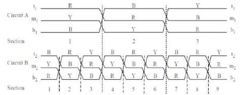
Figure 4. D/C Line with Ideal Nine Transpositions
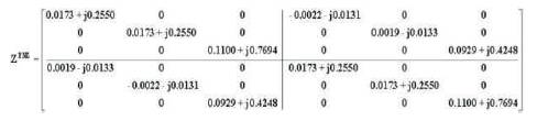
The elements of the inter-circuit mutual matrix are all equal to ZAB. This is equal to the average of all nine mutual impedances between the six conductors of the two circuits. The corresponding sequence matrix is calculated using any electrical phasing of circuits A and B, for RYB/RYB or RYB/BYR, is given by Matrix 13.
Matrix 13. Sequence Impedance Matrix
where,

In the sequence reference frame, this eliminates the PPS and NPS mutual coupling between the two circuits but not the ZPS mutual coupling which will always be present.
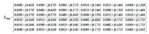
The calculation of overhead line parameters at power frequency as well as higher frequencies are now-a-days efficiently carried out using digital computer programs to reduce the complexity by hand calculations. The large array of structures with many different geometric forms makes the conception of a generic method for the calculation of surge impedances very complex. To overcome the complexity of manual iterative calculations, a program is coded to generate phase and sequence impedance matrices showing the effect of transpositions for 3, 6, and 9 transpositions of 400 kV, single ground wired, double circuit transmission tower. In the below Figures 5 and 6, each bar represents the actual physical element diagonal elements are the self impedances and off diagonal elements are the mutual impedances. The self phase impedance matrices and inter circuit mutual phase impedance matrices are not equal in case of Figure 5, and corresponding sequence impedance matrix having inter sequence mutual couplings with no zero elements.
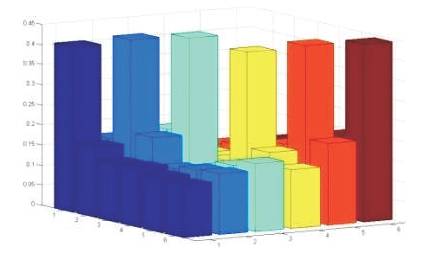
Figure 5. Untransposed Phase Impedance Matrix
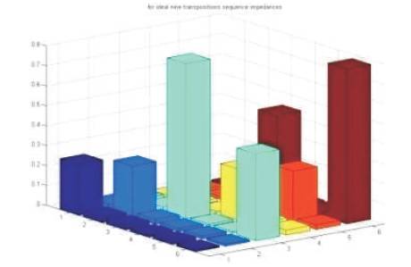
Figure 6. Untransposed Sequence Impedance Matrix
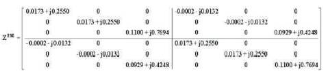
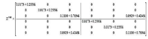
Figures 7 and 8, represents the line with ideal nine transpositions. The self phase impedance matrix of circuit A and circuit B are equal and the elements of inter circuit mutual matrix all are equal to ZAB, and PPS and NPS mutual coupling between the two circuits are eliminated in sequence matrix.
Matrix 14. Balanced Phase Impedance Matrix
Matrix 15. Balanced Sequence Impedance Matrix
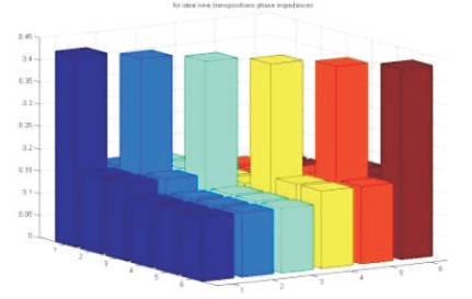
Figure 7. Ideal Balanced Phase Impedance Matrix for Nine Transpositions
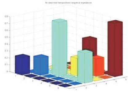
Figure 8. Ideal Sequence Impedance Matrix
Transmission lines functions as arteries that carry electricity from power stations to regions where the power is needed. In this paper, analysis was done on the impact of transposition on transmission line by studying one of the major factors of transmission line, the self and mutual impedance matrices which follows geometrical design of transmission line.
The study is general and also applies to mutually coupled cable circuits and mutually coupled transformer windings. The technique presented for a double circuit overhead line with one earth wire, can be extended to any geometry of the transmission lines.
The output and mathematical calculation hence shows an excellent resemblance in similarity by which it is proved that the impedance calculation has reduced the complexity by using programming technique. The same program can be used for any tower configurations i.e. for multiple circuit lines.