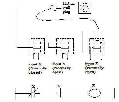
Figure 1. Comparison between Relay Logic System and PLC
Today energy is the most important basis for development of any country. Generation, transmission, distribution, and usage of energy are to be optimized for the proper conservation of energy. Electrical energy is generated from different sources like hydraulic power plants, thermal power plants, nuclear power plants etc. India has ample water sources to produce electrical energy. Presently the long time outage and fault detection during distribution are very serious problems. Also accidents are not uncommon in electrical transmission systems. It is too late to implement advanced systems for power distribution systems, if not implemented now. The main focus of the present work is to modernize the present systems with powerful tools like PLC and SCADA for automatic control of distribution systems. The automatic tap changer maintains the voltage of whole system normally. Thus much manpower could be reduced and major outages can be avoided with maximum safety of the system.
Power distribution networks are used for the regulation of supply to all over the country. High Voltage (HV) transmission systems are used in our country because of high transmission loss. Due to deficit of intelligent automation systems in the field of electrical power distribution system, power losses and accidents are not uncommon in our country. The haphazard development of distribution systems resulting in high system outages in addition to impecunious quality of supply are the reasons. Efficient operation and maintenance of distribution system is hampered by non-availability of system topological information, current health information of the distribution components like distribution transformers and feeders, historical data etc. The lack of use of efficient tools are the other reasons for poor operational planning and advanced methodology for quick detection of fault, isolation of the faulty section and service restoration etc. Presently, fault detection, isolation and service restoration takes a long time causing the interruption of supply for a longer duration. Manual meter reading, delay in billing, faulty and inaccurate metering, tampering of meters and pilferage of electricity are some of the main reasons for poor return of revenue to electricity utilities in India. Previously the power distribution automation and the communication infrastructure were by the application of microcontrollers [1,3]. For the power system design and analysis power flow analysis is used and MATLAB programming is used for software package [2]. Many international standards like IEC 61850, IEC 61499 etc are used for the automation of electrical power system [4,7]. Some of the systems use the CDMA wireless communication and analyse the system using various tools [6,11]. The present status of the distribution system is the 'smart grid' by using relays [5,8,10]. The substation is designed and automated using the latest tools PLC and SCADA to overcome the problems that arise in the power station [9,12,13]. It is too late to modernize these distribution networks without these advanced automation tools. The present work is to integrate complete operations of the electrical substation to the SCADA installed in a computer. The SCADA communicates with the PLC and the entire system control is done through PLC.
A PLC or programmable logic controller is a customized digital computer.
Control engineering has evolved is over time. In the past manual control was the only main method for controlling a system. More recently electricity has been used for control and early electrical control was based on relays. These relays allow power to be switched on and off without a mechanical switch. It is common to use relays to make simple logical control decisions. The development of low cost computer has brought the most recent revolution, the PLC. A PLC is a specialized digital computer. Unlike general purpose computers, a PLC is designed especially for industrial use with multiple input and output, rigid construction, immunity to electrical and mechanical impacts and ease of programming and reprogramming. When combined with supervisory control and data acquisition, they can allow monitoring and control of complex systems.
Figure 1 shows the comparison of relay logic system with PLC. The relay is usually defined as an electrically operated switch. To operate a switch mechanically, most of the relays use electromagnets. Presumably other operating principles are also applied in relays like solidstate relays. The application of relays where umpteen circuits must be controlled by single signal, or where it is imperative to control a circuit by low-power signal (with consummate electrical isolation between controlled circuits and control). The relays were used to perform logical operations in previous computers and profusely in telephone exchanges. The relay logic systems are using a number of relays to accomplish one control sequence. In relays, the no. of poles is limited to three so that more relays are to be used if same input is coming in many places.
Figure 1. Comparison between Relay Logic System and PLC
A PLC works by continually scanning a program. This scan cycle consists of 3 important steps as shown in Figure 2 and the detailed description of the scan cycle is illustrated in Table 1.
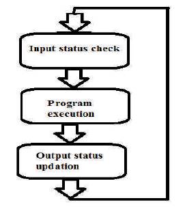
Figure 2. Scan Cycle
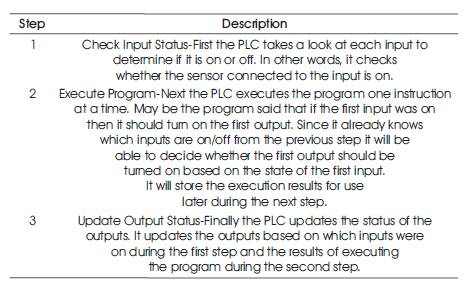
Table 1. Scan Cycle of PLC Operation
After the third step the PLC goes back to step one and repeats the steps continuously. One scan time is defined as the time it takes to execute the 3 steps.
Supervisory Control and Data Acquisition systems (SCADA) is one which controls at supervisory level and collects data through distribution system. It means that the supervisory control system is at the top of the real time control system. The process is controlled and monitored by the supervisory control system and is external to the control system. A separate or integrated real-time automated control system can respond quickly as possible for process changes. The processes are of 3 types: industrial based, infrastructure based and facility based. They are described below:
The main objective of the Automation of Electrical Power Distribution system is to automate the electrical power distribution system using PLC and SCADA and enhance the detection of variations in the voltage and temperature. In addition, the enhancement of fault and outage detection in the system and notification. The automation of the feeder switching also can be achieved by the system.
The design methodology (Figure 3) adapted to the system as follows: The present work of automated electrical power distribution system is done using PLC. The PLC being a mini-controller uses ladder based logic to control the distribution of power. Since the automated power supply is of large scale magnitude and importance, a modelsimulation is used to show the working. The work consists of one main station and four sub stations. Each of the substations consists of the feeders.
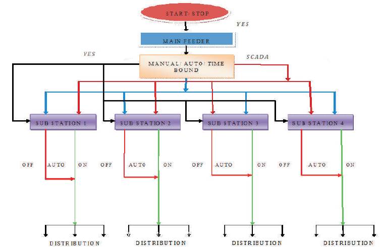
Figure 3. Design Methodology of Automated System
The system basically consists of 3 modes of operations as shown in Table 2.
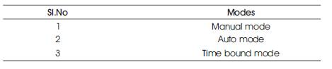
Table 2. Modes of Operations Carried out by the System
The manual mode is where the main station is ON and switched OFF through two different push buttons. This mode is the conventional mode where the substations can be switched ON only if the main station is switched ON. The feeders can be switched ON only if the corresponding Substation is switched on. The whole substations and the sub feeders have their own ON and OFF push buttons.
The second mode is the automatic mode, which in normal conditions acts like manual mode. But when the 'auto' switch (toggle) is switched ON the logic acts in a different way. If any of the sub feeders are switched OFF in the automatic mode, it gets OFF first but after a minor delay will restart again itself automatically using the PLC logic.
The next mode is the 'time bound' mode. This mode is controlled by SCADA. The time bound mode is where the operator can decide the hours in which the power can be distributed and held. That is if the operator sets a time between 5pm to 9pm; the sub feeder gets OFF from 5pm to 9pm and switches ON automatically after the time is over. The time delay and the range of operation can be set by SCADA. There are some problems related to the accuracy time during load shedding. This mode is useful for load shedding.
The present work focuses on a perfect conglomeration of PLC and SCADA and power supply control, which reduces human effort and throws light on a new dimension in automation of power distribution.
The automation of electrical power distribution system is achieved by using PLC and SCADA. The earlier methods used for automation were replaced by Programmable Logic Controller (PLC), which controls the whole system. Simplicity, flexibility, quick and more sophisticated control are the essential features of PLC.
The software part of the system consists of two components: PLC and SCADA. Ladder logic is the most commonly used PLC programming language. Ladder Diagram (LD) and Traditional ladder logic is a graphical programming language. It is Initially programmed with simple contacts that simulate the opening and closing of relays and Ladder logic programming has been expanded to include such functions as counters, timers, shift registers and math operations. The first two rungs of the ladder logic are utilized in the system as shown in the Figure 4.
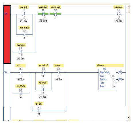
Figure 4. Ladder Diagram used in the System
SCADA is the supervisory control of the system. The operator can accomplish the task very easily by applying SCADA to the system. PLC programming and SCADA are combined together for the automation of electrical power distribution system. The SCADA system consists of one main window. The main window of the SCADA displays options for the selection of the other controlling windows. There are four windows in the system, which take part in the process for the operator to accomplish the task more easily as shown in Figure 5.
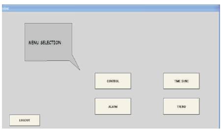
Figure 5. Menu Selection Window
The control window shows the status of the main station (Figure 6), substations and feeders and controls of all the stations and feeders. The selection of manual and auto mode also is from the control window. In auto mode, during the time of outage, time taken to restore the power in the substation also shown in Figure 7.
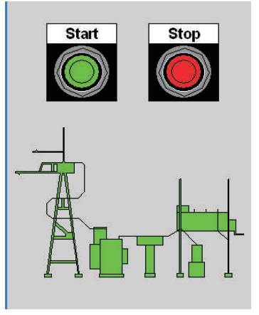
Figure 6. Main Station
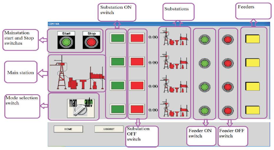
Figure 7. Main Control of the System
Time synchronizing is applied for the load shedding of feeders. The whole system should be in manual mode. The time synchronizing window shows the status of the feeders during the time of load shedding. The time in which the feeder should be off and the time in which it should be on are indicated in the window as shown in Figure 8.
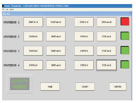
Figure 8. Time Synchronising of the System
The alarming system, which produces alarm in various fiasco conditions of voltage and temperature as shown in Figure 9. The primary side voltage of the main station will be measured in the alarm window.
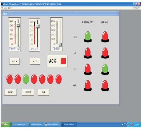
Figure 9. Alarming Condition in the System
Automatic tap changer is also present in the system, which maintains the output voltage of the main station constant.
The trend of the system produces the graphical representation of the various parameters like voltage, current, temperature etc. The real time graphical representation of the parameters like voltage, current, temperature etc can be monitored by the trend. It also represents the slight changes in the parameters. The variation of voltage indicated in Figure 10.
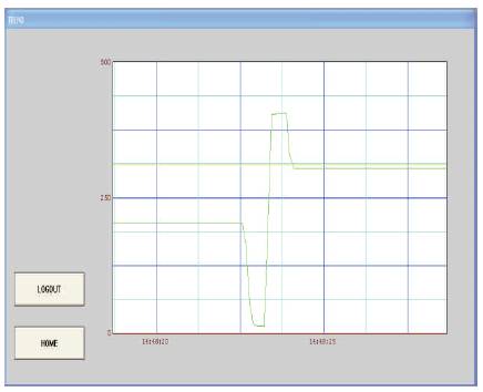
Figure 10. Trend of the System
The presented system for automation of electrical power distribution using PLC and SCADA eliminates some of the problems occurring in the earlier methods. This simple, flexible and reliable method allows the perfect functioning of the distribution system. The method ensures safest and fastest transmission and distribution of power. Automatic restoration of power reduces time consumption and total outage time of feeders. The automatic tap changer maintains the voltage of whole system constant. The automation of electrical power distribution system is the easiest platform for the operator in this field.