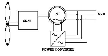
Figure 1. Principle and Operation of DFIG based WEC
This paper explains different converter topologies with different induction generators used for wind energy conversion system. In this focused area of renewable energy resources, wind energy conversion system is more popular than the other conversion systems. Four main types of induction generator used in wind energy conversion system (WECS) are Squirrel Cage Induction Generator (SCIG), Permanent Magnet Synchronous Generator (PMSG), Doubly Fed Induction Generator (DFIG), and Wound Field Synchronous Generator (WFSG). Presently, Doubly-Fed Induction Generator (DFIG) is widely employed in modern wind power industries. The maximum electrical power can be obtained in both wind speeds of above and below synchronous speed using DFIG. Also, it reduces the power rating of the converter. This paper mainly explains the study concepts of Power converter topologies used with Doubly Fed Induction Generator (DFIG) connected wind energy conversion system.
Wind energy conversion system is an important and popular one over other different conversion technologies [1]. Wind energy has the capacity of grown rapidly over the last few years and has become a fastest grown renewable energy technology [2]. Wind energy can be produced by running a wind turbine generator in a variable speed mode. Wind turbines are classified according to the rational speed, power regulation, and the generation system. According to the construction of the drive system, the turbines are classified into the geared and the direct drive type [4]. The direct drive system has advantages such as economical cost, smaller size, and less weight. Currently many topologies are used in stand-alone and grid connected wind energy conversion system. Wind Turbine Generators in the power system can be classified into three types according to the operating speed and the size of the converters.
With the sub classifications of
The term refers to the fact that the voltage on the stator is applied from the grid and the voltage on the rotor is induced by the power converter. This system allows a variable-speed operation over a large, but restricted range [5]. The converter compensates the difference between the mechanical and electrical frequencies by injecting a rotor current with a variable frequency. Hence, the operation and behavior of the DFIG is governed by the power converter and its controllers. Wind turbines with Doubly Fed Induction Generator (DFIG) consist of a wound rotor induction generator / Slip ring induction generator with requited rated power converter. The stator winding is directly connected to the main grid and the rotor is connected through the power converter. The DFIG technology is mainly used to allow the extraction of maximum electrical energy from the wind at lower wind speeds. It also minimizes the mechanical stresses occuring on the turbine during gusts of wind. The optimum speed of turbine produces maximum mechanical energy for a given wind speed. It is directly proportional to the wind speed. In addition to that, the DFIG technology is capable to generate or absorb reactive powers and hence it eliminates the need of capacitor banks installation required in the case of squirrel-cage induction generator.
An aerodynamic blade of wind turbine captures the wind power and it is converted in to its equivalent mechanical power [5]. A gear box attached with turbine is used to match the wind speed of the wind turbine and induction generator associated with it. The stator assembly of DFIG is directly connected to the AC mains and the slip ring wound rotor is fed from the Power Electronics Converter through slip rings. It is used to allow the DIFG cab be operated at different speeds with respect to different wind speeds. In this connection, we have to propose a frequency converter between the variable frequency induction generator and fixed frequency grid. The DC capacitor is used to link the stator and rotor side converters, which are used to allow the storage of power taken from induction generator for further power generation. The slip power at the rotor side can flow in both directions. i.e., to or from the rotor and the supply and hence the speed of the machine can be controlled by either rotor- side or stator-side converter in both above and below synchronous speed ranges. At the synchronous speed, the slip power taken from supply is used to excite the rotor windings [3]. And in this case machine behaves as a synchronous machine.
Power converters are used in wind energy conversion system for converting generated power level. The developments in power electronics and their capability in wind energy conversion allow the variable speed operations like Sub synchronous and super synchronous in the wind turbine. Two main converter topologies of power converter with DFIG are Standalone topology and Grid connected topology. Figure 1 shows the Principle and Operation of DFIG based WEC.
Figure 1. Principle and Operation of DFIG based WEC
Converters used in grid side are thyristor based converters. They have high power capacity and mainly used in high power applications.
Standalone converter system used PWM control method in general. IGBT is the popularly used semi-conductor because of turn- off capability. PWM converter may produce harmonics and inter harmonics due to high frequency switching. Filters are connected to remove harmonics [7].
Grid connected topologies with DFIG are classified on the basis of Grid side converters:
A thyristor grid side converter allows continuous control of inverter firing angle. To obtain the optimum energy, thyristor grid side inverters regulate turbine speed by the DC link voltage. A Voltage Source Converter (VSC) is used as a compensator. The error signal occurs between the reference side and actual side, the compensator current is used to drive the Pulse Width Modulated (PWM) control. The generation system uses two doubly fed induction machines with corresponding PWM rotor inverters connected to a common dc bus[6]. Figure 2 shows the Thyristor grid side converter.
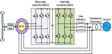
Figure 2. Thyristor grid side converter
To increase the system output power, the power mapping technique is used, where the Maximum Power is matched to the DC-link voltage. In addition to that, a derivative control is also used to control the stator frequency with respect to changes with the DC-linked voltage. The control system behaves like a MPPT (Maximum Power Point Tracking), which maps the generated power to a reference power and sets the operating DC voltage.
Figure 3 shows the Hard Switching Supply side Inverter.
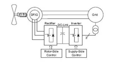
Figure 3. Hard Switching Supply side Inverter with Voltage Source Inverter (VSI)
Matrix converter is an AC-AC converter and an alternative of the DC link voltage-sourced converter. A matrix converter provides a large number of control switches that allows an independent control on the magnitude, frequency, phase angle of the output voltage and input power factor. Figure 4 shows the Conventional matrix Converter.
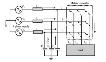
Figure 4. Conventional matrix converter
Multilevel converters are mainly used in high power variable wind power applications. Multilevel converter includes an array of power semiconductors and capacitor voltage sources, the output of which generate voltages with stepped waveform.
AdvantagesFollowing is a type of Multilevel converter
2.2.4.1 Neutral clamped or diode clamped converter (NPC)Neutral clamped type converter can be structured as 3- level, 5-level and even 7-level or more. The 3-level NPC is the most applied type in industry. There are four switches in 3-level NPC which are applied with diodes to a midpoint of the capacitor bank. To this converter all conventional (PWM) approaches are applicable. Figure 5 shows the Neutral clamped Converter.
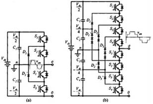
Figure 5. Neutral clamped or diode clamped converter (a) 3-level (b) 5-level
Z-source inverter is mainly used to obtain maximum power tracking control and delivering maximum power to the grid. ZSI is an alternative power circuit [8], which can be applied for both voltage buck and boost capabilities. Figure 6 shows the Z-source Converter.
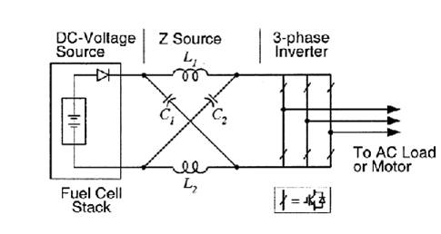
Figure 6. Z-source inverter
Main objective of the standalone wind energy conversion system is the control of load frequency and voltage. Standalone system is useful in remote area where power grid is not feasible. Generally DC-DC converters are used in the standalone system. DC-DC converters are implemented between the rectifier and the battery. DCDC converters used in standalone side are the following:
The buck-boost is one of the most popular non-isolated power stage topology, also called as step-up/down power stage. Power converter designer chooses the buckboost power stage with the required output inverted from the input voltage and the output voltage can be either higher or lower than the input voltage. The input current nature for a buck-boost power stage is discontinuous, or pulsating, because of the power switches in current pulses from zero to load current for every switching cycle. For the Buck chopper, energy only goes to the load when the switch closes. For the Boost chopper, energy only goes to the load when the switch opens. With the CUK converter energy is transferred when the switch opens and when it closes. Figure 7 shows the Power Converter WEC.
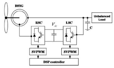
Figure 7. Power converter in Standalone WEC
Wind energy conversion system (WECS) is the most popular system in the renewable energy resources system. Power converter plays a vital role in WECS. In this paper, different popular converter topologies have been studied with DFIG. By studying and comparing the various converter topologies of grid side and standalone system based on DFIG WECS, its found that the Thyristor grid side inverter is very cheaper than others, but it generates more number of harmonics in the generated current in which there increase are losses and reduction in generator’s life. Hence, the thyristor is not suitable for taking output power under low wind speed conditions. In hard switched inverter topology, back to back PWM VSI is used, but it is very costly for smaller capacity. The Multilevel converter reduces the weight but commonly used for offshore wind farms. Matrix converter eliminates the DC-link stage and provides a more reliable system compared with others. Matrix converter has disadvantages of complicated control and cost and due to this, matrix converter topology has not yet been accepted and is undergoing research. Z-source inverter improves the reliability of the system and able to escape the shoot through fault. In a Standalone, side system with Buck-boost converter has cascade connection of converter and it is used to control the rotor speed.