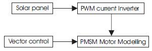
Figure 1. Block Diagram of proposed system
Permanent Magnet Synchronous Motor (PMSM) drives have been increasingly applied in a variety of industrial applications which require fast dynamic response and accurate control over wide speed ranges. However, there still exist challenges to design position-sensor less vector control of PMSM operating in a wide speed range, which covers both constant-torque and constant-power region. Field Oriented Control (FOC) of Permanent Magnet Synchronous Motor (PMSM) is one of the widely used methods for the speed control of the motor. The feasibility and effectiveness of various pulse width modulation techniques implemented for PMSM are addressed in this paper and verified by computer simulation. The whole drive system is simulated in MATLAB/SIMULINK based on the mathematical model of the system devices including PMSM and inverter. By using solar panel, the dc voltage is applied to a PWM inverter. The aim of the drive system is to have speed control by using solar panel. Simulation results show that the speed controller has a good dynamic response
Permanent Magnet Synchronous Motor drives (PMSM) offer many advantages over the induction motor, such as overall efficiency, effective use of reluctance torque, smaller losses and compact motor size. In recent years, many studies have been developed to find out different solutions for the PMSM drive control having the features of quick and precise torque response, and the field oriented control has been recognized as viable and robust solution to achieve these requirements. [2]
The practical application of the system, using direct torque control, is handicapped by the difficulty of starting under full load due to the unknown initial rotor position. A lot of efforts have been made to detect the initial rotor position. Among them, the most versatile method is to make use of the structural and magnetic saturation saliencies which exist in the PMSM. The structural saliency could be employed to acquire the position of the rotor axis, while the saturation saliency, which is generated by the rotor permanent magnets, can be used to detect the magnetic polarity [1]. The main objective of the vector control is achieved by using a d-q rotating reference frame synchronously with the rotor flux space vector. In ideally field-oriented control, the rotor flux linkage axis is forced to align with the d-axes. In field-oriented control, the torque equation becomes analogous to the DC machine [3]. The inverter plays an important role to provide better sinusoidal voltage or current and speed control of machines become finer. It is possible only if inverter gets better gate pulses [4]. Figure 1 shows the proposed system.
Classical controllers (PI, PID) are widely used in industry while more advanced techniques of control, such as adaptive controllers are less used in industry. This is due to the fact that:
The vector control is one of the types of speed control of a PMSM motor which is implemented to generate the speed, torque and current of an induction motor. The direct vector control depends on the generation of unit vector signals from the stator or air gap flux signals. The air gap signals can be measured directly or estimated from the stator voltage or current signals. The stator flux components can be directly computed from stator quantities. In these systems, rotor speed is not required for obtaining rotor field angle information. Here, the actual motor currents are converted to synchronously rotating frame currents using park transformation. The resulting dc quantities are compared with the reference d-axis and qaxis components. The output of the controllers are used to generate the pulse width modulated signals for switching the devices in the inverter bridge feeding the motor.
By using solar panel, dc voltage is obtained which is given to the input of PWM inverter. This paper presents a nonlinear model of PMSM, which incorporates both the structural and saturation saliencies to enable the numerical simulation of new rotor position detection. In this model, the self and mutual differential inductances of the phase windings are expressed as functions of the rotor position and stator current. Based on the model, the Field Oriented Control (FOC) scheme is simulated within the MATLAB/ SIMULINK environment.
Figure 1. Block Diagram of proposed system
A photovoltaic cell, commonly called a solar cell or PV, is the technology used to convert solar energy directly into electrical power. A photovoltaic cell is a non mechanical device usually made from silicon alloys. A PV cell is essentially a large diode that produces a voltage when exposed to sunlight. Figure 2 shows the Equivalent circuit.
The PV generator is a non linear device and is usually described by its equivalent circuit and IV characteristics. The electric model of a solar system is composed of diode, two resistances and current generator [1].. The relation between the current (I) and voltage (V) is given by,
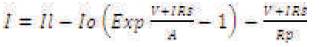
Where Ii , Io and I are the photocurrent, the inverse saturation current and operating current, Rs and Rp are the series and parallel resistances respectively which depend on the incident of solar radiation and the cell temperature. A= KT/q, where K and q are Boltzmann constant and electronic charges respectively. The equation (1) has been rewritten as:
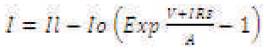
The current and voltage parameters of PV generator are Ipv =I and Vpv =ns Ns Vs, where ns and Ns are number of series cells in the solar panel and of series panels in the generator.
Figure 3 shows that the characteristics of PV panel depends on the variation of irradiance. The short circuit current varies in proposition to the insulation level, while the open circuit voltage is approximately constant. Consequently the power will increase accordingly. Each curve has a maximum power point which is the optimal operating point for an efficient use of solar array.
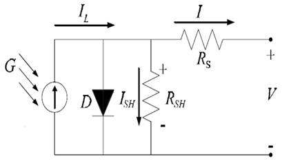
Figure 2. Equivalent circuit of PV Cell
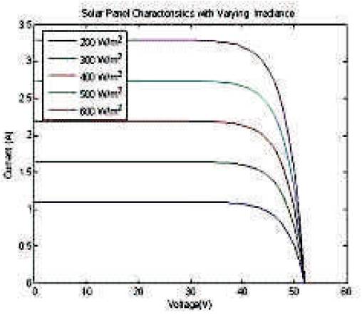
Figure 3. VI Characteristics of PV Panel
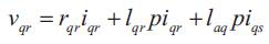
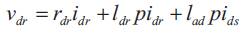
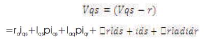
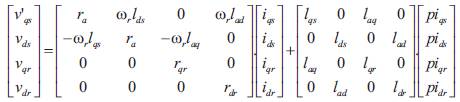
The voltage equations for the permanent magnet motor in rotor reference frame are [5] [6]


Where, ψ- air gap flux linkage
Eqn. (1) can be rewritten as
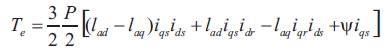
The electrical torque developed is
The torque balance equation is
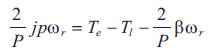
Where all voltages (v) and currents (i) refer to the rotor reference frame. The subscripts qs, ds, qr and dr correspond to q and d axis quantities for the stator(s) and rotor(r) in all combinations, ra denotes the armature resistance, lqs denotes quadrature axis inductance, lds denotes direct axis inductance etc. and Te is the developed torque. The rotor speed is given by ω and the load torque by Ti . J is the moment of inertia, P is the number l of poles and β is the co-efficient of viscous friction. The derivative operator is represented by the symbol p.
Representing the voltage eqns. (3)-(7) into a state space representation as given below:
Field Oriented Control demonstrates that an induction motor or synchronous motor could be controlled like a separately excited dc motor by the orientation of the stator magneto motive forces or current vector in relation to the rotor flux to achieve a desired objective. It usually refers to controllers which maintain a 900 electrical angle between rotor and stator field components. In DC motors, the flux and torque producing currents are orthogonal and can be controlled independently. The magneto motive forces developed by these currents are also held orthogonal. The torque developed is given by the equation
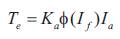
Hence the flux is only dependent on the field windingcurrent. If the flux is held constant, then the torque can be controlled by the armature current. For this reason, DC machines are said to have decoupled or have independent control of torque and flux. In AC machines, the stator and rotor fields are not orthogonal to each other. The only current that can be controlled is the stator current. Field Oriented Control is the technique used to achieve the decoupled control of torque and flux by transforming the stator current quantities (phase currents) from stationary reference frame to torque and flux producing currents components in rotating reference frame.
Advantages of FOC:
Figure 4 shows the circuit model of a single-phase inverter with a centre-taped grounded DC bus, and Figure 5 illustrates the principle of pulse width modulation.
As depicted in Figure 5, the inverter output voltage is determined in the following.
Also, the inverter output voltage has the following features:
Figure 6 shows the circuit model of three-phase PWM inverter and Figure 7 shows the waveforms of carrier wave signal (Vtri ) and control signal (Vcontrol ), where inverter output line to neutral voltages are VA0 , VB0 , VC0 , inverter output line to line voltages are VAB , VBC , VCA respectively [7] [8]..
As described in Figure 7, the frequency of Vtri and Vcontrol is
Where, fs = PWM frequency and f1 = Fundamental frequency
The inverter output voltages are determined as follows:
Where, VAB = VA0 – VB0 , VBC = VB0 – VC0 , VCA = VC0 – VA0
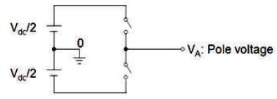
Figure 4. Circuit model of a single-phase inverter
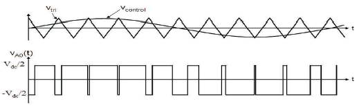
Figure 5. Pulse width modulation
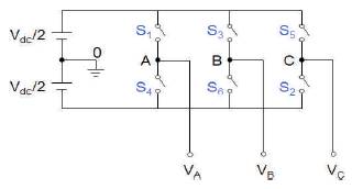
Figure 6. Three-phase PWM Inverter
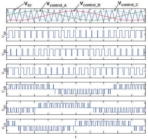
Figure 7. Waveforms of three-phase sine-PWM inverter
In this simulation model, the PWM inverter input voltage is fed from the solar panel. From the voltage controller, it will give the voltage supply to the PWM Inverter.
The PMSM motor is fed by a PWM inverter. The switching frequency is usually kept constant. Figure 8 shows the Simulink Model for PMSM Motor. They are based on the principle of triangular carrier wave of desired switching frequency and is compared with the error of controlled signal. The error signal is obtained from the sum of reference signal generated in the controller and the negative of the actual motor current feedback from the motor [7]. The voltage signal obtained triggers the gates of the voltage source inverter to generate the desired output. If the error command is greater than the carrier, the inverter leg is held switched to the positive polarity [8].. When the error command is less, the inverter leg is switched to negative polarity. This will generate the PWM signal and the output voltage of the inverter is proportional to the current error command. Figure 9 shows the PWM Inverter With Solar Panel.
The output of the voltage is 21.35 V which is given as the input dc voltage to the PWM inverter circuit. By using MATLAB, we will get the result of speed of an induction motor which is shown in Figure 10. Figure 11 shows the Torque Characteristics of PWM Inverter and Figure 12 shows the Characteristics of Solar Panel.
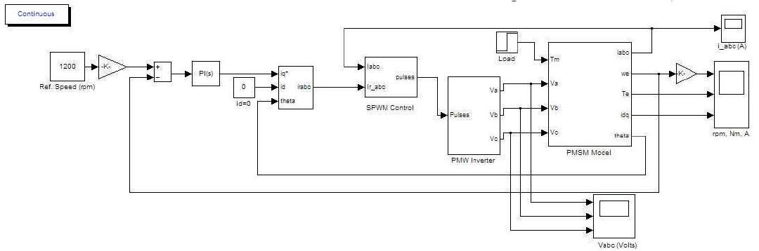
Figure 8. Simulink Model for PMSM Motor
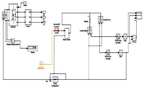
Figure 9. Simulink Model for PWM Inverter With Solar Panel
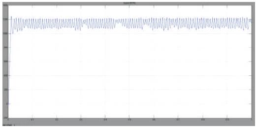
Figure 10. Speed Characteristics of PWM Inverter with Solar Panel
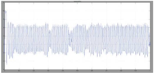
Figure 11. Torque Characteristics of PWM Inverter with Solar Panel
Figure 12. Current, Voltage and Power Characteristics of Solar Panel
The work simulated in this paper proves the possibility of utilizing a PV cell to supply a PMSM Motor through three phase bridge inverters. We can conclude that this paper will be a contribution to the analysis of solar panel to run a PMSM motor by means PWM inverter. The experimental step up and its analysis may be considered for future purpose.