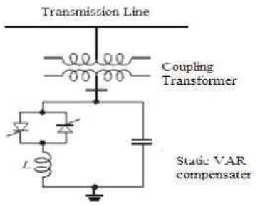
Figure 1. Static VAR Compensator
This paper presents performance evaluation of real time radial distribution system with different compensating devices. The performance of real time radial distribution system was investigated using Real Time Distribution system data with different compensating devices for different operating conditions. The performance evaluation of distribution system is analyzed by placing shunt capacitor, SVC and STATCOM independently; voltage profile and total losses are compared under different system operating conditions. To demonstrate the effectiveness of the proposed method, a 110/11KV distribution substation is selected for analyzing the performance and results are presented.
Modern power utilities are facing many challenges due to ever increasing complexity in their operation and structure. The lack of new generation and transmission facilities and overexploitation of existing facilities together with the increase in load demand make these problems more likely in modern power systems. Voltage stability is the ability of a power system to maintain adequate voltage magnitude so that when the system’s nominal load is increased, the actual power transferred to that load will increase. The main cause of voltage instability is the inability of the power system to meet the demand for reactive power. Voltage instability is the cause of system voltage collapse, in which the system voltage decays to a level from which it is unable to recover. Voltage collapse may lead to partial or full power interruption in the system. Providing adequate reactive power support at the appropriate location solves voltage instability problems. There are many reactive compensation devices used by the utilities for this purpose, each of which has its own characteristics and limitations. However, the utility would like to achieve this with the most beneficial compensation device. This paper compares the currently available and most commonly used shunt-compensation devices.
Distribution system performance evaluation usually relies on reliability index to evaluate system operation. Hence, important aspects form system operations such as voltage profile, line/transformer, over loadings are normally assessed for scenarios. Recently, some researchers have focused on improving distribution system performance assessment. For that in [1], the probability distributions from the distribution system reliability indices are evaluated using a Sequential Monte Carlo Simulation (SMCS) approach from the service adequacy perspective. In [3], an analytical technique for distribution system reliability is developed, where the probability of successful islanding is taken into account. In [4], the stochastic nature of the system’s operation with parallel connected customer controlled DG units is evaluated from the adequacy point of view. Capacitor placement has been discussed in technical literature since 1980’s as the distribution system planning and operation started. Shunt capacitors are commonly used in distribution systems to reduce the power losses, to improve the voltage profile and to increase the power flow. The [5] method of placement of capacitor done by considering some constraints like load constraints and operational constraints are presented and simulated annealing is used to solve this optimization. A [6] new and fast energy loss calculation technique is presented in this literature. The optimal placement of capacitors using loss minimization as the object is presented in lot of literatures. The energy loss calculation method is changed to make it faster. Genetic algorithm is used to solve the optimal placement problem.
It is well known that shunt compensation can be used to compensate reactive power. Shunt capacitor or FACTS devices can be used for this purpose. FACTS controllers are very expensive. Reactive power compensation is the most effective way to improve both power transfer capability and voltage stability. The control of voltage levels is accomplished by controlling the production, absorption and flow of reactive power. The generating units provide the basic means of voltage control, because the automatic voltage regulators control field excitation to maintain scheduled voltage level at the terminals of the generators. To control voltage throughout the system, we have to use additional devices to compensate reactive power. Reactive compensation can be divided into series and shunt compensation. It can be also divided into active and passive compensation. The next section gives a brief introduction of different solutions for improving system stability. But mostly consideration will be focused on shunt capacitor banks, Static Var Compensator (SVC) and Static Synchronous Compensators (STATCOM), which are the part of group of active compensators called Flexible AC Transmission Systems (FACTS).
The devices used for these purposes may be classified as follows:
Shunt capacitors are relatively inexpensive to install and maintain. Installing shunt capacitors in the load area or at the point that they are needed will enhance the voltage stability. However, shunt capacitors have the problem of poor voltage regulation and beyond a certain level of compensation, a stable operating point is unattainable. Furthermore, the reactive power delivered by the shunt capacitor is proportional to the square of the terminal voltage; during low voltage conditions, Var support drops, thus compounding the problem.
Procedure:
Static VAR systems are applied by utilities for several purposes. The primary purpose is usually for rapid control of voltage at weak points in a network. Installations may be at the midpoint of transmission interconnections or at the line ends. Static VAR Compensators are shunting connected static generators / absorbers whose outputs are varied as to control voltage of the electric power systems. In its simple form, SVC is connected as Fixed Capacitor and Thyristor Controlled Reactor (FC-TCR) configuration as shown in Figure 1. The SVC is connected to a coupling transformer that is connected directly to the ac bus whose voltage is to be regulated.
Figure 1. Static VAR Compensator
Static Synchronous Compensator (STATCOM) is a device that is capable of generating and/or absorbing reactive power. It consists of a Voltage Source Converter (VSC), a dc energy storage device, a coupling transformer connected in shunt to the distribution network through a coupling transformer. The VSC converts the dc voltage across the storage device into a set of three-phase ac output voltages. It can continuously generate or absorb reactive power by varying the amplitude of the converter voltage with respect to the line bus voltage so that a controlled current flows through the tie reactance between the STATCOM and the distribution network. When system voltage is low, the STATCOM generates reactive power (STATCOM capacitive). When system voltage is high, it absorbs reactive power (STATCOM inductive). The VSC uses forced-commutated power electronic devices (GTOs, IGBTs or IGCTs) to synthesize its terminal voltage from a DC voltage source. In an IGBT based STATCOM model, fixed DC voltage is used. The overall scheme of the STATCOM circuit is shown in Figure 2 and the control system block diagram is shown in Figure 3.
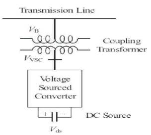
Figure 2. Static Synchronous Compensator (STATCOM)
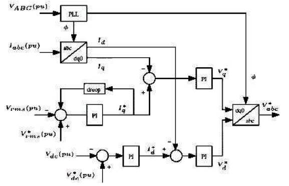
Figure 3. Control system block diagram
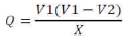
The real and reactive power injected by the STATCOM is given by the following equations.
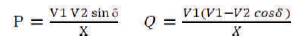
Where δ is the angle of V1 with respect of V2. In steady state, the voltage V2 generated by the VSC is in phase with V1 (δ = 0), so that only reactive power is flowing (P=0). If V2 is lower than V1, Q is flowing from V1 to V2 (STATCOM is absorbing reactive power). On the reverse, if V2 is higher than V1, Q is flowing from V2 to V1 (STATCOM is generating reactive power). The amount of reactive power is given by the following equation:
This section describes the PWM-based control scheme for the DSTATCOM. The aim of the control scheme is to maintain constant voltage magnitude at the point where a sensitive load is connected, under system disturbances. The voltage controller analyzed in this work is exhibited in Figure 3 below, which employs the dqo rotating reference frames because it offers higher accuracy than stationary frame based techniques.
In this figure, VABC are the three-phase terminal voltages, Iabc are the three-phase currents injected by the devices into the network, Vrms is the rms terminal voltage, Vdc is the dc voltage measured in the capacitor and the superscripts * indicate reference values. There are four PI regulators. The first one is responsible for controlling the terminal voltage through the reactive power exchange with the ac network. This PI regulator provides the reactive current reference Iq*, which is limited between +1 pu capacitive and -1 pu inductive. This regulator has one droop characteristic, usually ±5%, which allows the terminal voltage to suffer only small variations. Another PI regulator is responsible for keeping constant dc voltage through a small active power exchange with the ac network, compensating the active power losses in the transformer and inverter. This PI regulator provides the active current reference Id*. The other two PI regulators determine voltage reference Vd* and Vq*, which are sent to the PWM signal generator of the converter, after a dqoto- abc transformation. Finally, Vabc* are the three-phase voltages desired at the converter output.
The distribution network model of Bijapur substation is shown in Figure 4. This station is fed from Bijapur 220/110KV receiving station. The area of study for the analysis of Bijapur distribution station region is where number of customers are within one lakh and type of customers include residential, commercial or industrial. This system is used to evaluate the performance of distribution system. A real radial distribution system of Bijapur District has been considered with 15 feeders, 3 transformers as shown in Figure 4. Table 1 shows the Details of Distribution Substation and Table 2 shows the Details of Feeders.
Simulink model of distribution System is shown in Figure 5.
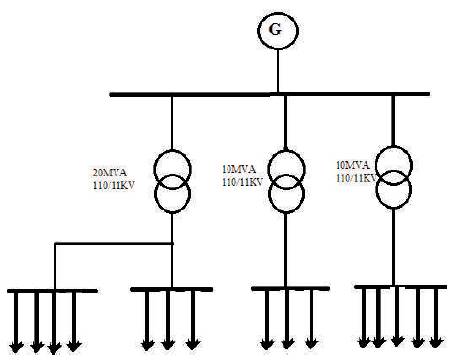
Figure 4. Radial distribution system with 15 feeders and 3 Transformers
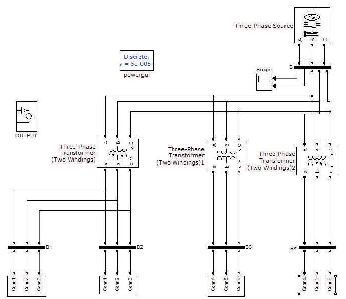
Figure 5. Simulink model of distribution system
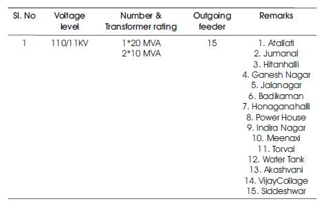
Table 1. Details of Distribution Substation
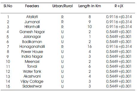
Table 2. Details of Feeders
Figures 6, 7, 8 and Table 3 illustrate the simulation results with respect to Voltage Profile, Real Power, Reactive Power, Total Power Loss respectively.
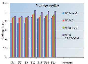
Figure 6. Voltage profile
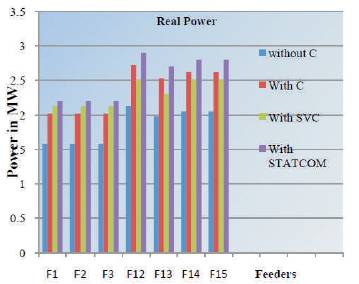
Figure 7. Real Power
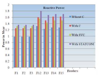
Figure 8. Reactive Power
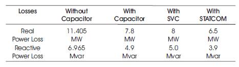
Table 3. Total Power Loss
A comparison of performance evaluation of distributed system [7] for different compensating devices like shunt capacitor, SVC and STATCOM for voltage stability enhancement and line loss reduction is presented in this paper. The voltage stability is an important issue as far as distributed system is concerned. The shunt capacitor, SVC and STATCOM will provide reactive power under different operating conditions and hence enhance the voltage stability and power transfer capability. However, by comparing the three approaches, it is concluded that, STATCOM will provide better result in terms of loss reduction and voltage profile. However, the controllers are expensive when compared to the shunt capacitor.