Figure 1. Schematic diagram of the proposed system
This paper presents a method of integrating Active Power Filter (APF) in Photo Voltaic(PV) system. Distributed Generation (DG) concept is attracting the attention of power sector engineers throughout the world due to its technical, economical and environmental benefits. Among the various possibilities of DGs, photovoltaic (PV) systems have drawn prominent attention in spite of their high cost and poor conversion efficiency. Power quality issues such as harmonics, are inevitable in such distribution systems which must be sorted out. Separate Passive/Active Filters can be used for this purpose. However, single VSI Converter can be made used for processing and connecting PV energy to system as well as for power Quality improvement of the whole system. This reduces the complexity and cost of the system significantly. The proposed PV System with single converter acting as APF is not only able to track the maximum power point of the photovoltaic energy, but also compensates harmonic currents from the grid line and correct the power factor. Peak detection method of control strategy is employed in APF for power quality improvement. P&O algorithm is used for achieving Maximum Power Point Tracking of the PV generator. The proposed system of APF embedded in PV system is simulated using MATLAB/SIMULINK and tested for power quality improvement under the maximum Power Point Tracking of PV generator.
Investigation of possibilities of effective utilization of renewable energy sources in power sector is the present day interest of system engineers which motivate the use of small distributed generation units in the power distribution systems [3] . These systems also have no exception from Power quality issues such as harmonics, voltage flickers as they consist of power electronic converter/inverters for processing the output of generating units before connecting to the grid. These problems are further magnified by the unavoidable usage of nonlinear and dynamic loads in the distribution system. These circumstances demand the use of effective power quality improvement methods to maintain the Quality of power.
Though Passive or active filters are the solution, Passive filters cannot compensate the harmonics greatly and also cause other problems such as resonances in the system. Thus, they cannot be effective regardless of their low costs. Usage of Active Filters is the best solution for this problem.
Shunt Active Power Filter (SAPF) [9] can compensate for the harmonics, correct the power factor and is a responsible component for the enhancement of power quality in the system. They operate as controlled current sources in injecting current harmonic components to the power distribution system. The control objective of SAPF primarily consists of generation of reference current wave form for each phase and driving the inverter by generating gating signals to track the reference wave form. Several strategies for the generation of reference compensation currents are available in literature [7]. The most popular instantaneous p-q theory can provide an instantaneous and accurate reference compensating current [4, 5]. In this transformation of a-b-c axes to d–q, synchronous reference frame is done for harmonic and reactive power compensation. However, the Synchronous Reference Frame (SRF) strategy [6] only computes the sinusoidal fundamental components of the load currents; the reactive power compensation and a zero neutral current thus cannot be achieved if the load imbalance at the fundamental frequency occurs. A phase-locked loop (PLL) for each phase must be used. In addition to these theories, there are many controlling techniques such as extraction of load current RMS component[8], indirect current control [10], algorithm based on the real component of fundamental load current (I cosF) [11] etc., available in literature. Singh et al. [12] have presented a review on the classification of active filters for power quality improvement based on converter type, topology and the number of phases. To achieve full compensation of both reactive power and harmonic currents of the load, this paper presents a simple method to determine the SAPF reference compensation currents using dc voltage PI controller, source voltages and source currents. This method does not require any reference frame transformations. Hysteresis band current control PWM (Pulse Width Modulation) strategy is used to drive Current Controlled Voltage Source Inverter (CC-VSI) . [2].
Among the various possibilities of DGs, photovoltaic (PV) systems [13],[14] have drawn prominent attention from both industry and academic communities, in spite of their cost and poor conversion efficiency due to the following merit list
Modeling of the PV systems has been addressed by many [15-18]. Another prominently addressed issue is Maximum Power Point (MPP) Tracking (MPPT). In [19], right from 1968, totally 19 MPPT algorithms have been reviewed. Among the different MPPT techniques, perturb and observe (P&O)/hill climbing methods are widely used in algorithms owing to their simplicity, low cost and easy implementation.
It can be concluded that, even though there exists a limited emphasis on the control of PV cell in the literature, the power quality improvement of PV systems is rather less except a few [20-23]. In these, also majority of techniques use Filters as additional equipment dedicated purely for power quality improvement. The proposed system uses single converter for both connections of PV cells and Power quality improvement which greatly reduces the cost and complexity.
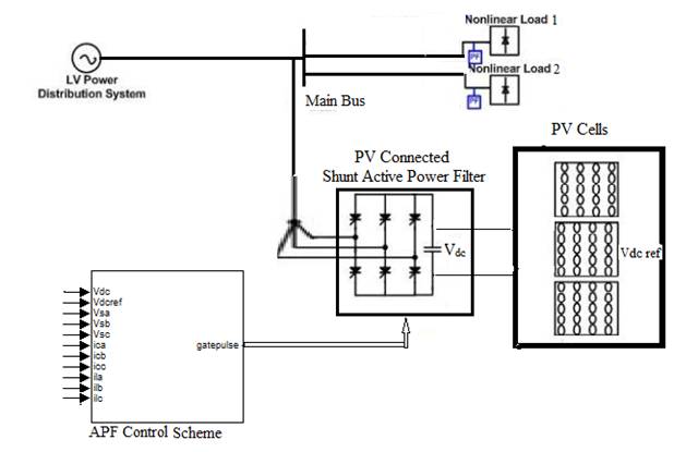
Figure 1 shows the proposed system and consists of a PV based DG system, synchronized with the grid and supplying local load as well. The PV cell is modeled with reasonable accuracy. The control algorithms are established to 1) control the converter dc-link voltage to extract the maximum power from the PV system, MPPT 2) generate the reference current for the APF to compensate the harmonics and regulate the power factor.
Figure 1. Schematic diagram of the proposed system
The contents of this paper are organized as follows: Section 1 describes the structure of the PV system considered along with PV generator modeling and MPPT control algorithm. Section 2 describes control scheme of SAPF and generation of control signals by proposed Peak detection method of controlling SAPF. Simulation results and discussions are given for different test conditions in section 3. The last section concludes this paper.
Solar energy is inexhaustible and clean form of energy. Developing solar energy power system can solve the energy crisis of exhausting in fossil fuel. Recently, photovoltaic arrays are widely used in medium sized grid with domestic utilities. Latest developments in the PV system topology is single stage PV system which are simpler, economical and more efficient than the two stage system. The Schematic diagram of the single stage system is shown in Figure 2. with its basic controls. Active Power Filter of the system working as ac/dc converter synthesizes the ac voltage with available DC voltage from PV cells. Control signals for Hysterisis band controller will be derived from Peak detection controller. Peak detection control is used for Active power Filter to generate reference currents for harmonics suppression and power factor maintenance. This controller is also tuned for the extraction of MPPT of PV system. Thus the APF which is the main constituent of the proposed system is responsible for (i) connecting the PV cells to the grid (ii) maintaining MPPT of the PV system (iii) maintaining power quality by eliminating harmonics and correcting power factor of the whole system.
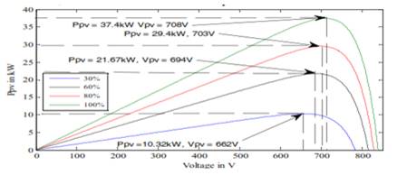
Figure 2. Variation of the PV generator power with insulation
A more approximated yet relatively accurate model was proposed in [1]. The equivalent circuit with current source representing the photo current (I PH ), a diode, a series resistance to account for internal resistance to the current flow and a parallel resistance to consider the leakage current, is considered in this model. The same model has been considered for analysis in this paper. According to this model, for a PV panel, with Ns number of series cells and Np number of parallel cells, the output current can be given by equation (1) [1]
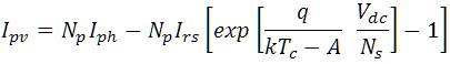
Where Ipv is the output current of the PV array, Vdc is the output voltage and Tc is working temperature of the cell, other parameters are:
Np and Ns are the Number of parallel and series cells, ISC is Cell's short circuit current, I rs is Cell reverse saturation current, q is Charge of an electron, k is Boltzmann's constant, Ideality factor is A, Cell's reference temp is Tref and Short circuit current temperature coefficient of cell is KI
The photo current, Iph and the power output, Ppv of the PV generator are given as (2) [1]

The PV array with Ns and Np cells is modeled using the basic blocks in MATLAB/SIMULINK.
For the dc/ac converter of Figure 1, universal bridge block is considered but its PWM pulses are generated according to the control algorithm explained in section 1.
The power output of the PVcell is nonlinearly dependent on the operating voltage as depicted in Figure 2. For a particular incident insulation and temperature, there is only one unique operating voltage, at which the PV panel needs to be operated to extract maximum power and hence maximum efficiency from it. Thus, a suitable mechanism which is capable of detecting the changes in the operating conditions and can give the information about operating voltage at which the PV system needs to be operated in order to get maximum efficiency is necessary. This objective is carried out by MPPT system. In Figure 2, 100% of insolation corresponds to 1000W/m2 [1]
In Perturb & Observe(P&O)algorithm, the voltage is varied in both positive and negative directions with a small value, known as perturbation ΔV. At last, the system will settle with the voltage that corresponds to the maximum power. The P&O algorithm changes the voltage at constant sampling rate to track the maximum power irrespective of change in operating conditions. Figure 3 shows the flow chart of P&O algorithm. Even though P&O has the disadvantages of getting confused over rapidly changing atmospheric conditions and oscillations around MPP in the steady state, it is easy to implement and requires less hardware, with reasonable accuracy. Hence, a variant of P&O,known as dp/dv algorithm [1] is used for the MPPT to compare with the performance of the proposed algorithm.
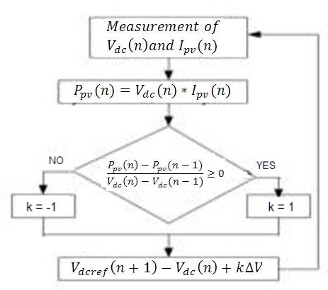
Figure 3. Flow chart of P&O algorithm for MPPT
General block diagram showing control scheme of a shunt active power filter is shown in Figure 4. The current reference circuit generates the reference currents required to compensate the load current harmonics and reactive power, and also try to maintain constant the dc voltage across the electrolytic capacitors. Also, the compensation effectiveness of an active power filter depends on its ability to follow with a minimum error and time delay, and the reference signal is calculated to compensate the distorted load current. Well tuned PI controller unit keeps the total dc bus voltage constant and equal to a given reference value. The reference value of the voltage is equal to the operating voltage of PV generator system. Small amount of power required to meet the losses in the inverter circuit are taken into consideration by the dc voltage control unit.
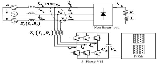
Figure 4. Basic Compensation Principle of Shunt Active Power Filter (SAPF)
Shunt Active Power Filers are generally aimed at compensating displacement power factor and lowfrequency current harmonics generated by non-linear loads. All the different strategies available to get the reference currents for driving the APF try to generate reference signals including compensating components for power factor and Load harmonics.
In this paper, a simple method is used to generate the source reference currents using DC voltage error and load current peak detection[2]. The main characteristic of this method is the direct derivation of the compensating component from the load current, without the use of any reference frame transformation. Figure 5 shows the proposed scheme used to generate the current reference signals required by a SAPF.
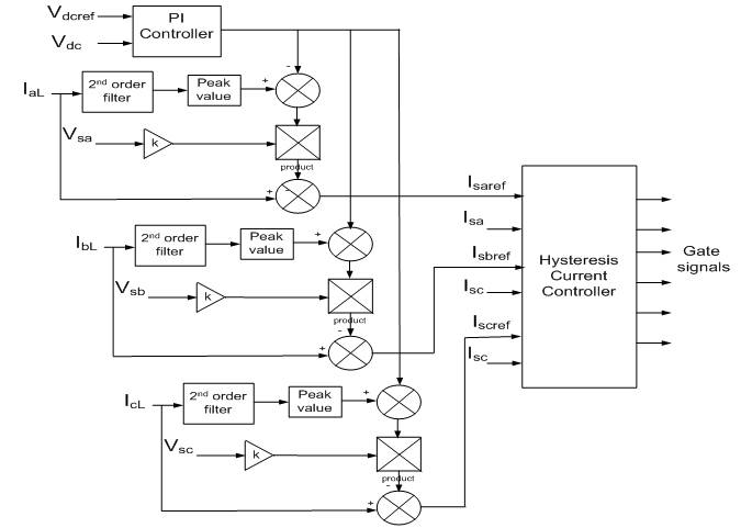
Figure 5. Generation of Reference currents required by SAPF
In this control strategy, the fundamental component, il1 of the distorted load current is extracted by filtering. The band-pass filter is used and tuned at the fundamental frequency (50 Hz), so that the gain attenuation introduced in the filter output signal is zero and the phase-shift angle is 1800. The output current of the filter is equal to the fundamental component of the load current but phase shifted by 1800. If the load current is added to the fundamental current component obtained from the second-order band-pass filter, the reference current waveform required to compensate only harmonic distortion is obtained. In order to provide the reactive power required by the load, the current signal obtained from the second-order band-pass filter Il1 is synchronized with the respective phase to- neutral source voltage, so that the inverter ac output current is forced to lead the respective inverter output voltage, thereby transferring the required reactive power. During the operation, inverter consumes small amount of real power to meet the switching losses and to keep dc voltage constant. The reference current wave form must also take this component into consideration. Thus, the sinusoidal reference current waveform obtained from reference current generator has the amplitude equal to the fundamental component of the load current plus or minus the error signal obtained from the dc voltage control unit. In this way, the current signal allows the inverter to supply the current harmonic components, the reactive power required by the load, and to absorb the small amount of active power necessary to cover the switching losses and to keep the dc voltage constant. Similar scheme is necessary for each phase.
The control circuit implementation of the peak detection method is simple and does not require complex calculation. The use of this method minimizes the distortion introduced on current harmonics.
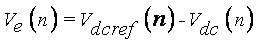
The three phase reference currents (peak value) for the control of active filter are generated in accordance with the PI controller error between the average dc bus voltage Vdc (n) and its reference value Vdcref (n) of the active filter. The dc bus voltage error Ve (n) at nth sampling instant is
This error signal Ve(n) is processed in PI controller and output K (n) at nth sampling instant is expressed as

where KP and KI are the gains of the controller.
The active filter is comprised of three-phase IGBT (Insulated Gate Bipolar Transistor) based current controlled VSI bridge. The upper device and the lower device in one phase leg of VSI are switched in complementary manner. The switching logic for “phasea” is formulated as follows: if isa < (i*sa - hb ), upper switch is OFF and lower switch is ON in the phase “a” leg, then Sa = 0. If isa > (i*sa +hb ) upper switch is ON and lower switch is OFF in the phase “a” leg, then Sa = 1. Between the transitions the previous value of switches are maintained where switching function for switches of phase “a” is the width of the hysteresis band around reference currents. Similarly, the switching logic of the other two phases (“b” and “c”) is formulated.
Ideal compensation requires the mains current to be sinusoidal and in phase with the source voltage, irrespective of the load current nature. The source reference currents, after compensation, can be given as
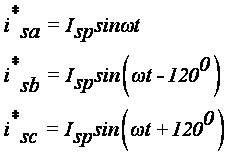
where Isp is the amplitude of the desired source current, while the phase angle can be obtained from the source voltages. Hence, the waveform and phases of the source currents are known, and only the magnitudes of the source currents need to be determined.
The system parameters considered for the study of SAPF with proposed peak detection method for PI controller are Vs = 100 V (Peak), f = 50 Hz, Rs = 0.1 Ω, Ls= 0.15 mH, Rf = 0.1 Ω, Ls = 0.66 mH, R1 = 6.7 Ω, 15 Ω; L1 = 20mH, CDC = 2000 μF, Vdcref = 220 V. In case of PI the gains chosen are kp= 1 and ki = 9. Initially, the load chosen is of R1 = 6.7 Ω, L1= 20mH and later, a 15 Ω is connected across this R-L combination.
Figure 6 Shows Current injected by PV generator in to the system. At 1.5sec, load is increased which results in increased current of pv generator. The power output of the PV generator is presented in Figure 7 which shows that the PV generator is tracking Maximum power according to MPPT algorithm. The nonlinear operating characteristics of the PV generator obtained by operating the considered PV cell for different insolations at stand still is shown in Figure 8, which suggests that, for Maximum power extraction at different insolations, the operating voltage is somewhere between 200&250V. Figure 9 shows the operating voltage of PV generator when connected in the system. It is evident from this figure that the PV generator is operating at the voltage corresponding to Maximum power.
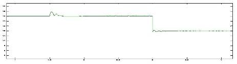
Figure 6. Current injected by PV generator into system at pcc
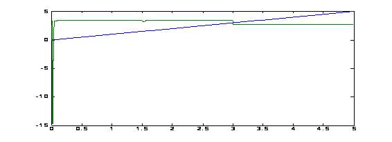
Figure 7. Power output of the PV generator
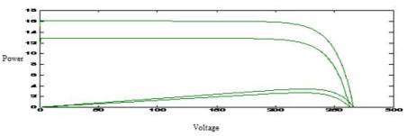
Figure 8. Stand still Operating characteristics of PV generator showing voltage corresponding to maximum power
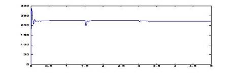
Figure 9. Operating voltage of PV generator when connected in system
The performance results of Shunt Active Power Filter with peak detection method are presented in Load current of phase which is highly non liner as shown in Figure 10. The source current of phase a is shown in Figure 11 which is sinusoidal with harmonics compensated by APF. FFT analysis for performance evaluation of APF is done and has been found that THD (Total Harmonic Distortion) of Load current of phase a is 28.04 where as it is equal to 5.02 for source current which is within the standard limits. Figure 12 shows the APF THD spectrum. not only compensates harmonics, but also corrects system power factor without any reactive power source which is evident from Figure 13 that shows source voltage and current wave forms of phase 'a' which are in phase.
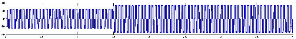
Figure 10. load current of phase a
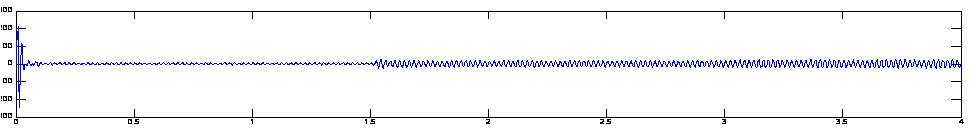
Figure 11. source current of phase a
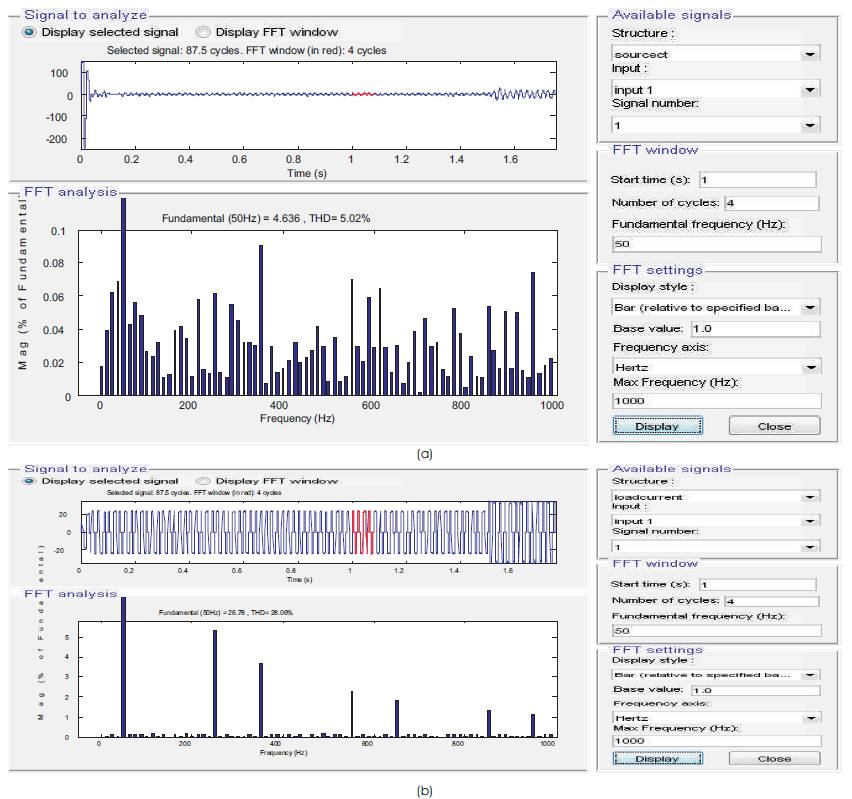
Figure 12(a). THD spectrum of source current of phase a,(b)load current of phase a
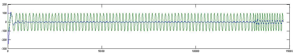
Figure 13. Source voltage and current of phase a
Power Quality improvement in a Photo Voltaic system is obtained by integrating Shunt Active Power Filter into the system. Separate converters for connection of PV cells and Compensation of current harmonics is eliminated and Single VSI converter with IGBT switches is tuned to damp out the harmonics injected by nonlinear load, as well as to process the PV cell output for feeding into the distribution system. A simple control algorithm for APF which is free from reference frame transformations and complex mathematical formulations is used. Perturb & Observe(P&O)algorithm is implemented for searching Voltage to extract maximum Power from PV generator for different insolations. The results obtained proved the well functioning of APF in damping Harmonics in source current and extracting power from PV generator.