Figure 1. Electric Charging of EV
Electric Vehicles (EVs) have gained popularity in recent years due to its sustainability. However, the charging process for EVs can be inconvenient and time-consuming, particularly when relying on conventional charging stations that necessitate manual vehicle connections. This research aims to develop a wireless charging system for electric vehicles that incorporates position alignment technology. The objective is to enhance the charging experience for EV owners, improving efficiency while reducing the environmental impact associated with traditional charging methods. The system utilizes a combination of wireless charging technology and sensors to detect the position of the EV and align it with the charging pad using Internet of Things (IoT) technology. This ensures an optimized charging process, enabling quick and efficient charging of the EV.
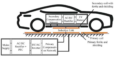
Electric Vehicles (EVs) are becoming increasingly popular as the next generation of vehicles, because it produces produce zero tailpipe emissions, thus aligning with the objective of reducing carbon emissions. In comparison to traditional Internal Combustion Engine Vehicles (ICEVs), EVs offer greater energy efficiency and lower running and maintenance costs. EV charging systems can be categorized as either wired or wireless. Wired chargers involve heavy cables and mechanical plugs, whereas wireless chargers eliminate the need for physical contact, providing enhanced safety, convenience, and weatherproofing, making them well-suited for harsh environments. EVs can be charged at home or at businesses, and in the future, charging options may expand to include various locations such as workplaces, parking lots, or street charging stations. Figure 1 depicts a typical wireless charging system for EVs.
Figure 1. Electric Charging of EV
An inverter circuit is responsible for generating a highfrequency current, which is then supplied to the transmitter (Tx) coil, creating a high-frequency magnetic field. As this magnetic field passes through the receiver (Rx) coil, it induces a voltage that is subsequently rectified and utilized to charge the battery. To compensate for the reactive power required by the coupled coil, resonant networks can be connected to both the Tx and Rx coils. In order to achieve optimal magnetic coupling, it is crucial to align the Tx and Rx coils so that their centers coincide. However, practical operation can lead to misalignment, thereby reducing the system's efficiency due to the degradation of magnetic coupling. To ensure the highest level of system efficiency, position detection has been incorporated to locate both coils in their aligned positions. Additionally, the system is continuously monitored and controlled online through an Internet of Things (IoT) platform. Once the aligned position is detected, the controller initiates the charging process for the EV's battery. Real-time battery status can be accessed from anywhere and at any time through ThingSpeak, and when the battery reaches full charge, the user receives an automatic notification.
Nutwong et al. (2021) presents the technique to detect the aligned position between transmitter and receiver coils, used in wireless charging for electric vehicles. A retro-reflective photoelectric sensor is adopted, which can enhance the accuracy and reliability of the conventional position detection system. With the presented method, the system is operated at maximum efficiency throughout the operation. Furthermore, IoT technology is also introduced in the proposed system, where remote monitoring and control can be achieved. Experimental measurements of the system efficiency with and without the presented technique are compared to validate the proposed system.
Das and Chakraborty (2018) presents the technique to detect the aligned position between transmitter and receiver coils, used in wireless charging for electric vehicles. The retro reflective photoelectric sensor is adopted, which can enhance the accuracy and reliability of the conventional position detection system. With the presented method, the system is operated at maximum efficiency throughout the operation. Furthermore, IoT technology is also introduced in the proposed system, where remote monitoring and control can be achieved. Experimental measurements of the system efficiency with and without the presented technique are compared to validate the proposed system. Sabki and Tan (2014) reviewed the existing wireless power transfer solutions used in electric vehicle battery charger. The different levels of battery charger are discussed based on the recommended practice by SAE J-113. The concept of each solution is reviewed and evaluated considering the performance of battery charger, power electronic limitations and the circuit topologies. Furthermore, the credits and disadvantages of the wireless power transfer technologies, compensation and power electronics requirement for electric vehicle are discussed and compared in detail.
Ahmad et al. (2017) provides a comprehensive, state-ofthe- art review of all the wireless charging technologies for Electric Vehicles (EVs), characteristics, and standards available in the open literature, as well as sustainable implications and potential safety measures. A comparative overview of conductive charging and wireless charging is followed by a detailed description of static wireless charging, Dynamic Wireless Charging (DWC), and quasi-DWC. Roadblocks, such as coil design of power pads, frequency, power level limitations, misalignment, and potential solutions, are outlined.
Das et al. (2018) examined methods of Wireless Power Transfer (WPT), including short-range as well as mid-range transmission. The technology and science behind WPT and its future scope are discussed in detail. While a lot of research has been done on this topic in the past decade, a large part of it is yet to be explored. The topics further discussed are Road-Powered Electric Vehicles (RPEVs) and Online Electric Vehicles (OLEVs) are also discussed and these vehicles can revolutionize the transport system. But they require a high initial investment.
The coil design is a critical factor in the development of wireless charging systems, as it plays a crucial role in transmitting electrical energy from the power source to the device being charged. To achieve optimal efficiency, performance, safety, reliability and various parameters are taken into consideration during the coil design process. These parameters include the selection of the core material, the number of turns in the coil, the size and shape of the coil, and the spacing between the coils (Zhang et al., 2016).
The core material used in the coil can be either air or a ferromagnetic material such as ferrite. Ferrite offers higher efficiency and a longer transmission range, but it comes at a higher cost. The number of turns in the coil determines the strength of the magnetic field generated, which directly affects the efficiency and range of the charging system. The size and shape of the coil, as well as the spacing between the coils, impact efficiency, range, and magnetic coupling between the transmitting and receiving coils. Figure 2 illustrates the coil design for wireless charging in electric vehicles.
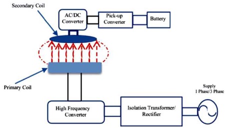
Figure 2. Coil Design on Wireless Charging Parameters for Electric Vehicle
Moreover, the frequency and waveform of the electrical energy being transmitted also influence the coil design. The frequency is determined based on the power requirements of the charging system, while the waveform is designed to ensure safe and efficient transmission. Designing the coil for wireless charging systems is a complex process that involves optimizing multiple parameters to achieve efficient and safe charging of the device. Computer simulations and modeling techniques are commonly employed to fine-tune the design and ensure that the charging system meets the necessary requirements for safety, efficiency, and overall performance.
Wireless charging systems have gained significant popularity as a convenient and cable-free method of charging Electric Vehicles (EVs). Similar to wireless charging systems used for smartphones and tablets, the EV wireless charging system consists of two main components: the charging pad, which is positioned on the ground and connected to a power source, and the receiving pad, located on the underside of the EV, which receives the transmitted electromagnetic energy from the charging pad (Machura & Li, 2019). Figure 3 illustrates the wireless electric vehicle charging system.
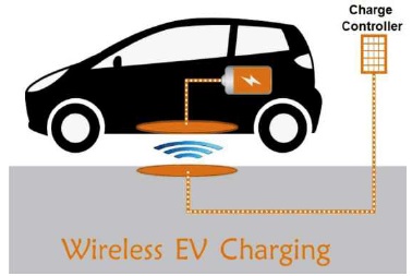
Figure 3. Wireless Electric Vehicle Charging System
The transmission of electromagnetic energy from the charging pad to the receiving pad is then converted into electrical energy, which in turn charges the EV's battery. These charging pads are equipped with communication systems that enable them to communicate with the onboard computer of the EV, ensuring safe and efficient charging. In comparison to traditional wired charging systems, wireless charging systems for EVs offer numerous advantages, including enhanced convenience, reduced clutter, and increased safety. Furthermore, they have the potential to make EVs more user-friendly and accessible to a wider range of individuals. However, it is important to note that the efficiency and reliability of wireless charging systems for EVs are still being evaluated and improved, as they are relatively new and currently more expensive than traditional charging methods.
Magnetic Wireless Power Transfer (MWPT) technology enables the wireless transmission of electrical power through the use of magnetic fields. MWPT systems consist of two coils: the transmitter coil and the receiver coil (Ahmed et al., 2020). The structure of a typical magnetic wireless power transfer system for Electric Vehicle (EV) charging is depicted in Figure 4.

Figure 4. Structure of a Typical Magnetic Wireless Power Transfer System for Electric Vehicle (EV) Charging
While the transmitter coil generates a magnetic field by connecting to a power source, the receiver coil receives this magnetic field and converts it into electrical power to either charge a device's battery or directly power the device (Qiu et al., 2013). Compared to traditional wired power transfer systems, MWPT technology has several advantages, such as eliminating the need for physical connections that clutter the environment, reducing the risks of electrical shock and fire hazards, and having the potential to work over longer distances. However, the efficiency of the power transfer remains a challenge in MWPT technology due to losses that occur due to resistance, eddy currents, and magnetic field leakage, which can reduce effectiveness and increase energy waste. Despite these challenges, continued research and development may make MWPT systems the standard for wireless power transfer in the future.
Electric Vehicles (EVs) can be wirelessly charged through the use of electromagnetic induction to transfer power from a charging pad to the EV battery. A magnetic field is generated by the coil in the charging pad, which is then converted into electrical energy by the receiver coil present in the EV to charge the battery (Fisher et al., 2014). The efficiency of the power transfer is maximized through a position alignment system, which ensures that the receiver coil in the EV is correctly aligned with the charging coil in the charging pad. This is achieved through the use of sensors that detect the position of the EV, allowing the system to adjust the position of the charging pad accordingly. The block diagram of the wireless charging for EV is shown in Figure 5.
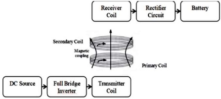
Figure 5. Block Diagram of Wireless Charging for EV
Wireless charging systems for EVs typically utilize an inductive power transfer mechanism. These systems consist of two primary components: a transmitting coil (primary coil) and a receiving coil (the secondary coil). The transmitting coil is usually installed on the ground or within a charging station, and it is designed as a flat, circular, or rectangular coil made of conductive materials like copper. Its main purpose is to generate an alternating magnetic field. On the other hand, the receiving coil is integrated into the EV and positioned underneath the vehicle, typically near the battery location. It also takes the form of a flat, circular, or rectangular coil made of conductive material. The role of the receiving coil is to capture the magnetic field generated by the primary coil.
When an Alternating Current (AC) flows through the primary coil, it creates a varying magnetic field around it. This changing magnetic field induces a voltage in the secondary coil, enabling wireless power transfer. To optimize the wireless power transfer efficiency, the primary and secondary coils are designed to operate at a specific resonant frequency. This frequency ensures efficient power transfer and minimizes losses. Proper alignment between the primary and secondary coils is crucial for effective power transfer. Various methods, such as visual guides or automated alignment systems, can be used to ensure that the coils are properly positioned for efficient charging.
Wireless charging systems incorporate various control and safety features to ensure efficient and secure charging operations. These features include communication protocols between the charging station and the vehicle, power regulation mechanisms, and safety measures to prevent overheating and overcharging. It is worth noting that the design of wireless charging systems, such as the shape, size, and specifications of the coils, may differ depending on the wireless charging technology being utilized. Moreover, adherence to relevant standards and regulations is crucial during the design phase to ensure that compatibility and safety standards are met.
To initiate the charging process, the driver positions the EV over the charging pad, which is typically located in a parking spot or garage. Once power is applied, the charging pad generates a magnetic field. The position alignment system utilizes sensors to detect the position of the EV and calculate the position of the receiver coil in the EV based on this information. The charging pad's position is then adjusted horizontally and vertically using a motorized system, based on the receiver coil's position, to ensure precise alignment with the charging coil, enabling power transfer to commence.
Power transfer begins when the receiver coil is correctly aligned with the charging coil. The charging pad generates a magnetic field that induces current in the receiver coil, which is subsequently converted into electrical energy to charge the EV's battery. Charging continues until the battery reaches full capacity, at which point the charging process automatically stops. Finally, once the charging process is complete, the driver removes the EV from the charging pad to proceed with driving.
This study focuses on a wireless power transfer system that enables the transmission of power without physical connections between the transmitter and receiver sections. In the transmitter section, an AC converter applies a frequency of 240 kHz to initiate the power transfer process. The received power in the receiver section is then utilized to recharge the battery and power of the electric vehicle. The wireless power transfer is facilitated by the transmitting coil, which transfers power at a frequency of 200.45 kHz with an output voltage of 14.0 V. However, due to losses incurred during the power transfer, the receiving coil receives a slightly lower voltage of 12.5 V at a frequency of 196.9 kHz. The implemented electric vehicle demonstrates a satisfactory correlation between the calculated and implemented results.
Table 1 presents the results obtained from the prototype system. As the distance between the transmitter and receiver coils increase there is a noticeable decrease in the received voltage. This reduction in voltage signifies a decrease in efficiency as the distance increases. It is evident that the efficiency of the wireless power transfer system is inversely proportional to the distance between the coils. To achieve maximum system efficiency, all losses and power supplies must be considered and optimized (Jang et al., 2012).

Table 1. Results of Prototype System
This analysis highlights the wireless power transfer system's functionality and performance in charging electric vehicles. By analyzing the results obtained from the prototype system, it is evident that the distance between the transmitter and receiver coils significantly affects the efficiency of power transfer. These findings emphasize the importance of optimizing the design and parameters of the wireless power transfer system to maximize efficiency and minimize losses. Further research and development in this area can lead to improved wireless charging technologies for electric vehicles, offering more convenient and efficient charging solutions.
This analysis emphasizes the correlation between the calculated results and the practical implementation of the wireless power transfer system in an electric vehicle. These findings provide valuable insights into the performance of the system and its potential for real-world applications. By considering various factors such as distance, losses, and power supply, it is possible to achieve a higher level of efficiency in the wireless power transfer process.
This exploration shows the effectiveness of the wireless power transfer system for powering electric vehicles. Through the analysis of the prototype system, a clear correlation between the calculated and implemented results is established. The obtained data, as presented in Table 1, clearly demonstrates the decrease in received voltage with an increase in distance, emphasizing the need for efficient alignment and proximity of the transmitter and receiver coils. By optimizing the system design, addressing losses, and considering the power supply, the overall efficiency of the wireless power transfer system can be improved, enabling its successful integration into electric vehicle charging infrastructure.
This research introduces a novel method for detecting the aligned position of the transmitter and receiver coils in wireless Electric Vehicle (EV) charging systems. The experimental findings provide evidence that the proposed method can significantly enhance system efficiency. The primary objective is to achieve optimal alignment between the primary coil and secondary coil, thereby minimizing energy loss during Wireless Power Transmission (WPT). To accomplish this, an integrated system comprising an Infra Red (IR) sensor, a buzzer, and a microcontroller is employed. Furthermore, the system incorporates integration with IF This Then That (IFTTT), enabling seamless user notification through G-mail for online battery status monitoring and timely alerts when the battery reaches full charge.
The demonstrated WPT-based quick charging method proves to be highly effective compared to conventional charging techniques. Traditional fast charging methods often suffer from substantial energy loss in the form of heat, resulting in prolonged charging times. In contrast, the proposed circuit design tackles these issues by reducing the charging duration and effectively managing heat generation during the charging process. Notably, the highest power loss in a wireless charging system occurs during the transmission from the primary coil to the secondary coil. To address this challenge, the method ensures maximum power transfer within a specific range, diminishing power loss as the distance between the coils increases. As technology advances at a rapid pace, the development of a quick charging method utilizing wireless power transfer becomes increasingly crucial (Lee & Han, 2014).
In order to validate the effectiveness of the fast charging circuit, comprehensive tests were conducted using input from a wireless circuit network. The receiver coil, already integrated into the EV, was connected to a 12V, 1.3AH battery at the receiver end. Under typical conditions, the battery requires approximately 12.59 volts when idle, and its operating voltage can reach up to 14.6 volts. By implementing the proposed charging system design, an impressive efficiency of approximately 11.8 volts was achieved in transferring power from the transmitter end to the receiver end. This facilitated the rapid charging of an empty battery to nearly its full capacity. Notably, these tests were conducted on a small scale, requiring only a modest amount of current (approximately 0.16 A). The ultimate aim is to expand and implement this concept on a larger scale, specifically for wirelessly charging EVs as they become more prevalent in the automotive industry. The proposed system is characterized by its simplicity, precision, and user-friendly operation, making it highly accessible for widespread adoption.
Future research efforts will be dedicated to conducting a comprehensive system analysis and designing enhancements to further optimize overall effectiveness. The objective is to refine the wireless charging system and ensure seamless integration with various EV models. By addressing the technical challenges associated with wireless charging, such as alignment optimization and power transfer efficiency, the proposed methodology holds great promise for the future of electric vehicle charging infrastructure. As the technology continues to evolve, the successful implementation of this wireless charging approach will contribute significantly to the advancement of sustainable transportation systems and help accelerate the adoption of electric vehicles on a global scale.
The development of a wireless charging system with position alignment technology for electric vehicles aim to address the inconveniences and time-consuming aspects of traditional charging methods. By incorporating wireless charging technology, sensors, and IoT technology, the system offers an efficient and userfriendly charging experience for EV owners. The elimination of manual plugging in and the utilization of position alignment technology streamline the charging process, reducing the time and effort required by the driver. This convenience enhances the overall experience of owning an electric vehicle. Furthermore, the wireless charging system contributes to the sustainability of electric vehicles by reducing the environmental impact of traditional charging methods. The system minimizes reliance on fossil fuel-powered stations, resulting in lower carbon emissions and promoting cleaner energy usage. Overall, this project serves as a significant step towards creating a more efficient and environmentally-friendly charging infrastructure for electric vehicles, facilitating the transition towards a greener transportation ecosystem.