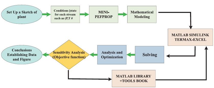
Figure 1. Methodology of Case Study
In this paper, exergy, exergoeconomic, and exergoenvironmental analysis of a gas turbine cycle and its optimization have been carried out by MINI-Reference Fluid Properties (MINI-REFPROP) and Matrix Laboratory (MATLAB) SIMULINK. The parametric study was carried out based on the Specific Exergy Costing approach. The mathematical models were developed and presented regarding mass, energy, and economy. The Excel and MATLAB LIBRARY TOOLS BOX are used to perform thermodynamic properties and research analyses. The analyses lead to valuable economic status benchmarks. The exergoeconomic factor, relative cost, total cost of energy loss, and energy destruction for the combustion chamber and work output were determined. The parametric study was conducted, considering the effects of the gas turbine inlet temperature, air compressor inlet temperature, and compressor pressure ratio. For the considered case study status, the combustion chamber in the plant revealed the highest amount of energy destruction (85%), leading to the recommendation that more attention be paid to boilers in terms of design, selection, operation, and maintenance, while the combustion chamber has a high improvement potential (91%).
The importance of developing thermal systems that effectively use energy resources such as natural gas is apparent. The first and second laws of thermodynamics govern the efficient use of energy resources. In recent years, increased use of fossil fuels, as well as increases in energy supply costs, have prompted researchers and manufacturers to seek out more efficient systems than ever before. The mini-REFPROP programme is a free sample version of the full REFPROP programme and is meant for use as a teaching tool in the introduction of thermodynamics to scholars. Also, with regard to environmental problems caused by emissions of fossil fuels and their effect on global warming and the ozone layer, the use of systems with lower contamination is inevitable. Exergoeconomics (Thermo-economics) is the branch of power engineering that, by means of the combined application of the first and second laws of thermodynamics (exergy analysis) and economics, allows the attainment of results otherwise impossible through traditional thermodynamic and economic analysis (Querol et al., 2013).
Exergy is taken as a rational basis for economic cost allocation between the resources and products involved in thermal power plant processes and for the economic evaluation of their thermodynamic imperfections. Mousafarash and Ameri (2013) performed exergy and exergo-economic based analysis of a gas turbine power generation system where the effects of the gas turbine load variations and ambient temperature on system performance variation were investigated. The gas turbine was significantly affected by the ambient temperature which led to a decrease in net power output. Furthermore, a reduction in gas turbine load resulted in a decrease in the exergy efficiency of the cycle as well as all the components. It was further revealed that an increase in ambient temperature has a negative effect on the exergy efficiency of the cycle, so this factor could be countered by using gas turbine air inlet cooling methods. In addition, an exergo-economic analysis was conducted to determine the cost of exergy destruction in each component and to determine the cost of fuel. The results showed that combustion chamber has the largest cost of exergy destruction.
Optimization and parametric analyses confirm that the exergo economic factor, total cost of exergy loss, exergy destruction for Combustion chamber and Work output, increase with the rise in the compressor pressure ratio, while they decrease with increasing the Air compressor inlet temperature. With the increase of the gas turbine inlet temperature, the total cost of energy loss, exergy destruction for Combustion chamber and Work output drop, while the total exergy destruction rate and the cycle network rise.
The effects of gas turbine inlet temperature on the cost flow of inlet turbine and compressor are presented. The cost flow of inlet turbine and compressor decrease from 72000 to 29000$/hr, and 65000 to 15000 $/hr, with the increase in gas turbine inlet temperature, from 1000 to 1500k, respectively. The contribution and the variation of cost of exergy destruction with load are lower for the other two main components.
If the exergy of the product of a thermal power plant (electricity generated) is used as the basis of value, then a rational evaluation of the cost production process can be conducted for both gas turbine and steam turbine power plants. This is an interesting application of exergoeconomics concepts to evaluate and allocate the cost of exergy throughout the power plant energy conversion processes, considering costs related to exergy inputs and investment in equipment. A number of studies on exergy and exergoeconomic analyses of thermal power plants have been carried out by several researchers. Among these studies include but not limited to the following.
Kaviri et al. (2011) carried out a comprehensive thermodynamic modeling and exergoeconomic optimization of a steam power plant. In this study, the sum of capital and operational costs in exergoeconomic approach was defined as the objective function. The objective function was minimized using Genetic Algorithm technique subject to list of constraints for obtaining the numerical values of the optimum design parameters. The results of exergoeconomic optimization showed that the cycle thermal efficiency improved by 0.85%, the boiler fuel consumption decreased by 0.085 kg/s, the total exergy destruction of the plant decreased by 9369 kW and the total cost (sum of capital and operational costs) of the plant decreased by197 $/h in comparison with the existing values for the studied shahid rajaei power plant.
Igbong and Fakorede (2014) carried out an exergoeconomic analysis on a 100 MW gas turbine power plant at Ughelli, Nigeria. Exergoeconomic optimization was performed using Engineering Equation Solver (EES) to estimate the cost rate associated with all the exergy streams at cycle state points and the cost of plant final product which is electricity. Two parameters were chosen as the decision variables: turbine inlet temperature, T3 and compressor pressure ratio, rp. The results showed that the unit cost of product decreased to a minimum point as the decision variables increased. The least unit cost of product was achieved at T3 = 1474 K and rp = 11.4. The plant thermal efficiency and exergy p efficiency were 31.05% and 30.81%, respectively. The study further showed that the combustion chamber had the least exergetic efficiency of 54.05% and exergy destruction rate of 238.681 MW.
Singh and Kaushik (2014) presented exergoeconomic analysis of a Kalina cycle coupled coal-fired steam power plant using Specific Exergy Costing (SPECO) methodology. In the study, cost-balance and auxiliary equations were developed and solved. In the topping cycle, the boiler and the turbine contributed maximum to the formation of product cost, while in the Kalina bottoming cycle, the components that contribute largely to the formation of the product cost were the evaporator and the turbine.
Elmzughi et al. (2020a) employed the exergetic efficiencies and exergy related costs and sensitivity cost analysis. For their case study, the potential improvement was found to be maximum in the boiler. The exergoeconomic factor for the boiler was 0.23, and the total cost of the plant was 14,000 $/hr. Radwan and Bahoor (2019) analyzed the performance of a hypothetical cogeneration power cycle in order to determine the main advanced parameters related to the energy utilization.
Elmzughi et al. (2020b) worked on a power plant cycle with a conventional steam rankine cycle, where the exergetic efficiency, exergy destruction, improvement potential, and exergy are determined. The total irreversibility decreases with the increase in the boiler temperature, and as the load increases by 1%, the total irreversibility increases by 4.5 Mega Watt (MW), with a maximum value of 440 MW. The maximum improvement potential takes place in the boiler, reheater, and condenser, with 163.0, 26.0, and 8.0 MW, respectively. The lowest exergetic efficiency is 9.2 % for the condenser, while the highest is for the deaerator with 97 %. Based on the Exergy cost theory.
Elmzughi et al. (2020c) study on a cogeneration steam power plant cycle with a total capacity of 350 MW. Under the considered status, the exergy destruction and potential improvement were found to be maximum in the boiler, with 75% and 81%, respectively, and the exergetic efficiency was 66.21% for the whole power plant cycle. The exergoeconomic factors and the total costs are calculated individually and for the whole thermal power plant, in which they are found to be 0.45 and 9249 $/hr., respectively. The unit cost of steam, work and cooling water for the plant were found to be 0.030, 0.014, and 0.45$/kWh, respectively.
Ehyaei et al. (2015) examined thermodynamic modeling of a combined cycle power plant as well as the effects of gas turbine inlet fogging system on the first and second law efficiency and net output power. Boyaghchi and Molaie (2015) carried out advanced exergy and optimization analysis of a real combined cycle with duct burners in Iran.
Ebadi and Gorji-Bandpy (2005) conducted an exergy analysis of the gas turbine cycle of a 116 MW power plant and concluded that the impact of rising input temperature in gas turbines may improve total exergy efficiency of the gas turbine cycle, and would reduce exergy losses. Similarly, they came to the result that maximum losses will occur in the combustion chamber in a gas-fired power plant.
Figure 1 shows the methodology implemented in this research. The workflow began by creating a sketch of the plant setup. After the setup, the condition of each stream can be considered, and it goes through the MINIREFPROP software process. The mini-REFPROP programme is a free sample version of the full REFPROP programme designed to be used as a teaching tool by scholars. The REFPROP "database" is actually a programme and does not contain any experimental information, aside from the critical and triple points of the pure fluids. The programme uses equations for the thermodynamic and transport properties to calculate the state points of the fluid or mixture. A mathematical model is an abstract and simplified description of a system using mathematical equations and diagrams. The modelling concepts in this topic provide context for understanding the process of mathematically describing a system with Simulink software tools. Then it moves on to the problem solving capability for analysis and optimization, followed by sensitivity analysis using the MATLAB library and the tools book.
Figure 1. Methodology of Case Study
The exergoeconomic analysis has been proven to be a high powerful tool for analyzing, evaluating, and improving energy conversion systems. Based on the idea that exergy represents the only rational basis not only for assessing the inefficiencies of thermal power systems but also for assigning costs to irreversibilities in the system, a methodological approach called Specific Exergy Costing Method (SPECO) analysis is applied to evaluate the performance of the selected gas turbine power plants. The case study represents a gas turbine power plant.
A gas turbine consists mainly of three components namely Combustion Chamber (CC), an Air Compressor (AC), and a Gas Turbine (GT), as indicated in Figure 2. Working fluid properties are obtained from the MINIREFPROP and MATLAB SIMULINK software packages. The gas turbine compresses air and mixes it with fuel that is heated to a very high temperature. The hot air-fuel mixture moves through the gas turbine blades, making them spin. The fast-spinning turbine drives a generator that converts a portion of the spinning energy into electricity. They are made up of three parts such as the compressor, which compresses the incoming air to a high pressure, the heater, and the fan, combustion area, which burns the fuel and produces high-pressure, high-velocity gas. The turbine extracts the energy from the high-pressure, high-velocity gas flowing from the combustion chamber. The main component of a gas turbine plant is the compressor.
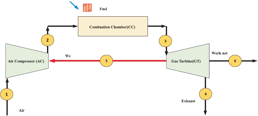
Figure 2. Schematic Drawing of the Considered Gas Turbine Power Plant Cycle
The nominal values of the design parameters of the gas turbine power unit are well defined in Table 1. Here, each and every description of state and the corresponding values are tabulated. A gas turbine is an internal combustion engine that operates with rotary rather than reciprocating motion. The performance of gas turbine engines is affected by the temperature, pressure, and isentropic efficiency of the turbine and air compressor.
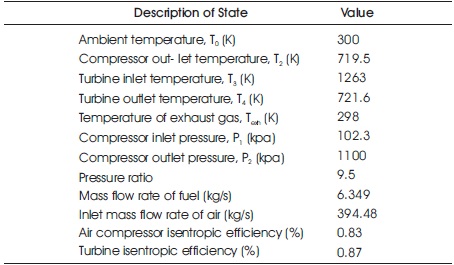
Table 1. Design Parameters of the Gas Turbine Power Unit
In order to conduct the energy, exergy, exergoeconomic, and sensitivity analyses, the main parameters associated with this study, mainly the natural gas, are itemized in Table 2. A detailed mathematical model is presented. These include thermodynamic and thermo-economic mathematical models for the working fluid processes. Here the cost of the fuel, capital recovery, total operating period, and the annual operating hours of the unit are also tabulated in Table 2.
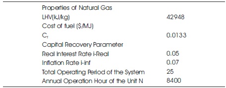
Table 2. Different Parameters used in the Calculations
In order to obtain the optimum parameters of the system, gas turbine cycle modelling was performed in MATLAB. The hypotheses considered in the analysis of the cycle are that all processes are supposed to be steady-state. Air and combustion products are supposed to be ideal gases. Air compressors and gas turbines are supposed to be adiabatic. The air compressor's inlet air temperature is 298 K, and its pressure is intended to be equal to 1.013 bar.
This paper focuses on the following items, which are the specific contributions of the current paper on this subject. A complete thermodynamic model of a major gas turbine power plant is performed. A simulation computer code is developed using MINI-REFPROP and MATLAB software to model all parts of the power plant, and this code is validated with actual data from the power plant. Exergy analysis of a gas turbine power plant is performed. An ergo-economic analysis of a gas turbine power plant is conducted. The effects of some major key parameters on both exergy and the exergo-economic performance of the cycle are investigated.
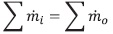
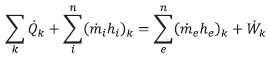
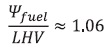
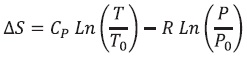
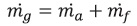
The thermodynamic mathematical models concerning the desired case study power cycle were presented elsewhere (Elmzughi et al., 2020a; Elmzughi et al., 2020b; Elmzughi et al., 2020c; Radwan & Bahoor, 2019; El-Emam & Dincer, 2013). Here, the relations are briefly presented for a steady-state, steady-flow process with negligible kinetic and potential energy changes. The Equations 1 to 3, which relate to the thermodynamic model, are given as follows.
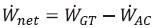
The mathematical approach, which could be useful to the machine operator, could be used to evaluate the performance of the gas turbine when the necessary diagnostic is given. The energy-related mathematical models are given by Equations 4 to 12 as,
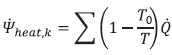
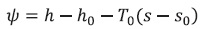

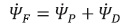
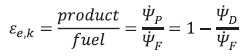
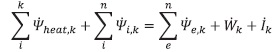
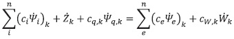
where,  is the component net exergy, is the specific heat,k exergy, ψF is the exergy rate, is the exergy balance, εe,k is the exergetic efficiency of the power cycle,
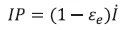
  is the ratio of the simplified exergy, and IP is the improvement potential (Elmzughi et al., 2020a; Elmzughi et al., 2020b; Elmzughi et al., 2020c; El-Emam & Dincer, 2013; Radwan & Bahoor, 2019).
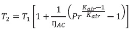
In the air compressor portion the calculations have been done by the help of Equations 13 and 14.
In the combustion chamber of a gas turbine, the energy that drives the whole system is added. The combustion chamber of a modern turbine typically consists of a cylinder with a second, smaller cylinder called the liner inside it. Equations 15 and 16 provide the formulas.

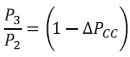
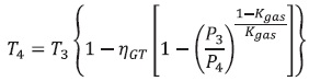
The atmospheric air flows through the compressor, which brings it to a higher pressure. Energy is then added by spraying fuel into the air and igniting it so that the combustion generates a high-temperature flow. The formulas are given in Equations 17 to 20.
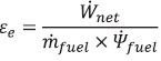
The energy associated with an energy quantity is a quantitative assessment of its usefulness or quality. The energetic performance coefficient is given by Equation 21 as,

A simple cycle gas turbine can achieve energy conversion efficiencies with the higher temperatures achieved in the Department of Energy's turbine program. The overall exergetic efficiency is given by the Equation 22 as,

First law efficiencies relate to the conversion of energy from one form to another and the conservation of the overall quantity of energy, without direct consideration for the quality of energy and it is given by Equation 23 as,
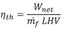
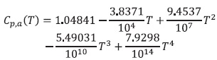
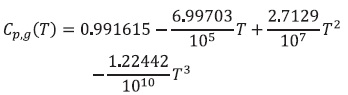
where, Cp,a and Cp,g are the specific heat at constant pressure and could be considered as a temperature variable function (Ameri et al., 2008).
Exergo-economics or thermo-economics is the branch of engineering that appropriately combines, at the level of system components, thermodynamic evaluations based on an exergy analysis with economic principles in order to provide the designer or operator of a system with information that is useful for the design and operation of a cost-effective system but that is not obtainable by regular energy or exergy analysis and economic analysis (Moran, 1989).
The economic mathematical models for the specific energy costing method are written and given by the Equations from 24 to 30 as (Elmzughi et al., 2020a; Elmzughi et al., 2020b; Elmzughi et al., 2020c; Radwan & Bahoor, 2019)
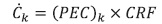
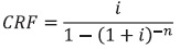

where, (PEC)k is the equipment purchase cost and CRF is the capital recovery factor. The factor takes the maintenance cost into account, and N is the annual operation hours of the plant. Table 3 presents the considered economic models required for the estimation of the purchase cost for each cycle component (Bolatturk et al., 2015; Ehyaei et al., 2011; Kabas et al., n.d; Lazzaretto & Andreatta, 1995; Selbaş et al., 2010; Tsatsaronis & Lin, 1990).
It is demonstrated by Equations 31 to 33 that there is a cost rate connected to the destruction of energy, and that both the individual and overall exergoeconomic factors are involved (Moran, 1989; Selbaş et al., 2010; Singh & Kaushik, 2014).
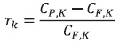
Relative cost difference is given as Equation 34,
In order to estimate the cost of the exergy destruction for each component of the thermal power plant, the auxiliar y exergoeconomic equations should be developed as shown in Equation 35.
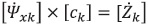
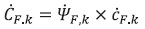
where, 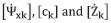 are the matrices of the exergy rate, exergetic cost vector, and vector of zk economic factors, respectively. In general, auxiliary equations must be formulated based on the F–P rules given by Ehyaei et al. (2011).
The linear system equation is given in Equation 36 as follows.
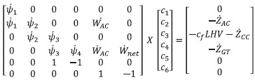
Table 4 tabulates the exergy destruction rate and exergy efficiency equation for gas turbines. Each component has its own energy destruction and additional information.
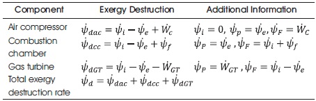
Table 4. Exergy Destruction Rate and Exergy Efficiency Equation for Gas Turbine
Table 5 tabulates the Cost Balance of Plant Components, including the component of cost balance and the additional information.
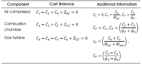
Table 5. Cost Balance of the Plant Components
The two rules for formulating the auxiliary equations are valid when finding the specific-costs of exergy associated with flows is desired (Lazzaretto & Tsatsaronis, 1999).
The total cost associated with the removal of exergy must be equal to the cost at which the removed exergy was supplied to the same stream in upstream components.
Each exergy unit is supplied to any stream associated with the product at the same average cost.
In order to evaluate the significance of a couple of operational and economic parameters, a parametric study is done to find out the expected variations in the performance of the plant and the associated cost of the outcome from the considered power plant. The thermodynamic properties are obtained through the use of the Excel package tools developed in the thermodynamics field. The tools developed by the University of Alabama research team and the platform for these tools is Microsoft Excel (Lazzaretto & Andreatta, 1995; Lazzaretto & Tsatsaronis, 1999; Tsatsaronis & Lin, 1990). The functions MINI-REFPROP and MATLAB SIMULINK are used to multiply the matrices, find the inverse matrix, and perform sensitivity analysis.
The effect of the compressor pressure ratio on the energetic efficiency and the second low efficiency is depicted in Figure 3. When the compressor pressure ratio is increased from 7 to 14, the exergetic efficiency and second low efficiency decrease linearly from 39 to 21% and 35 to 20%, respectively.
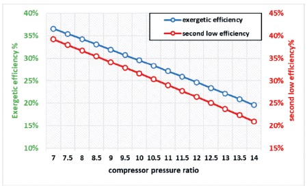
Figure 3. The Effects of Compressor Pressure Ratio on the Exergetic Efficiency and Second Low Efficiency
Figures 4 depicts the effect of inlet compressor temperature on energetic efficiency and second low efficiency as the temperature rises from 280 to 320 k. Exergetic efficiency and second low efficiency decrease linearly from 33% to 29% and 35% to 31%, respectively.
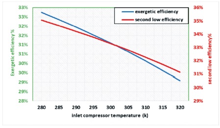
Figure 4. Effects of Inlet Compressor Temperature on the Exergetic Efficiency and Second Low Efficiency
Figure 5 represent the effect of gas turbine inlet temperature on energetic efficiency and second low efficiency as the temperature rises from 1000 to 1500 k. The exergetic efficiency and second-low efficiency are up from 24 to 32% and 21 to 34%, respectively.
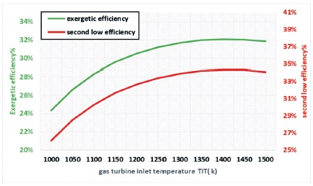
Figure 5. The Effects of Gas Turbine Inlet Temperature on the Exergetic Efficiency and Second Low Efficiency
The effect of the air compressor inlet temperature on the energy destruction and work compressor is presented in Figure 6. The total energy destruction rates of the cycle range from 689 to 778 MW and 644 to 997 MW, respectively, as the inlet temperature of the air compressor rises from 280 to 320 k.
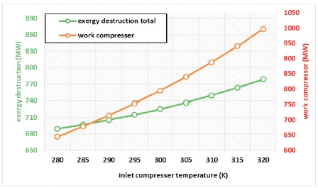
Figure 6. The Effects of Inlet Compressor Temperature on the Exergy Destruction and Work Compressor
Figure 7 presents the effects of the compressor pressure ratio on the exergy destruction and exergy improvement for each component. Here, the exergy destruction and exergy improvement of the turbine are mostly not affected by the compressor pressure ratio, while the exergy destruction and exergy improvement of the combustion chamber are increased from 544 to 947 MW and from 159 to 215 MW, respectively, with an increase in the compressor pressure ratio from 17 to 14.
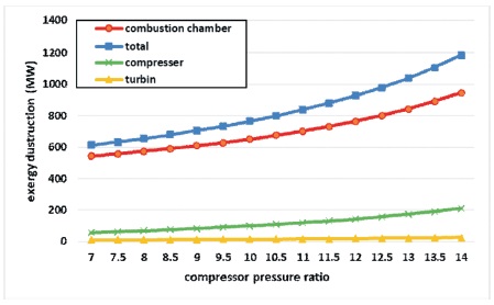
Figure 7. The Effects of Compressor Pressure Ratio on the Exergy Destruction for Each Component
The effects of the compressor pressure ratio on the exergy destruction and exergy improvement for each component are depicted in Figure 8. The total energy expenditure is very high in this case.
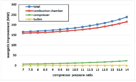
Figure 8. Effects of Compressor Pressure Ratio on the Exergetic Improvement for Each Component
Figure 9 presents the effects of gas turbine inlet temperature on the energy destruction for each component. Here, the exergy destruction of the turbine is mostly not affected by the compressor pressure ratio, while the exergy destruction and exergy improvement of the combustion chamber are dropped from 867 to 551 MW and from 210 to 148 MW, respectively, with an increase in the gas turbine inlet temperature from 1000 to 1500 k.
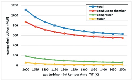
Figure 9. Effects of Gas Turbine Inlet Temperature on the Exergy Destruction for Each Component
Figure 10 depicts the effects of gas turbine inlet temperature on exergetic improvement for each component, as well as the total exergetic improvement's declination.
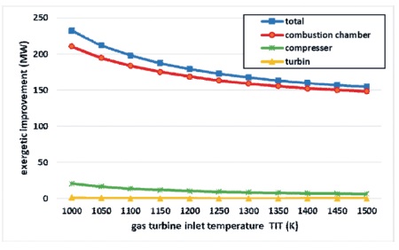
Figure 10. Effects of Gas Turbine Inlet Temperature on the Exergetic Improvement for Each Component
Figure 11 present the effects of gas turbine inlet temperature on energy destruction and work. The energy destruction work compressor and work turbine decreased from 964 to 628 MW, 1701 to 541 MW, and 2209 to 1041 MW with the increase in the gas turbine inlet temperature from 1000 to 1500 k, respectively.
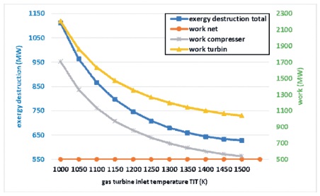
Figure 11. The Effects of Gas Turbine Inlet Temperature on the Exergy Destruction and Work
The effects of inlet compressor temperature on the cost flow of the inlet turbine and compressor are presented in Figure 12. With an increase in inlet compressor temperature from 280 to 320 K, the cost flow of the inlet turbine and compressor increases from 31000 to 42000 $/hr and from 25100 to 21900 $/hr, respectively.
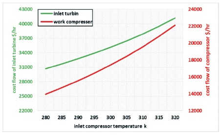
Figure 12. The Effects of Inlet Compressor Temperature on the Cost Flow of Inlet Turbine and Compressor
The effects of gas turbine inlet temperature on the cost flow of the inlet turbine and compressor are presented in Figure 13. The cost flow of the inlet turbine and compressor decreases from 72000 to 29000 $/hr and from 65000 to 15000 $/hr., respectively, with the increase in gas turbine inlet temperature from 1000 to 1500 K.
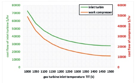
Figure 13. The Effects of Gas Turbine Inlet Temperature on the Cost Flow of Inlet Turbine and Compressor
Figure 14 depicts the effects of gas turbine inlet temperature on the energy destruction cost for each component. Here, the exergy destruction cost of the turbine is mostly not affected by gas turbine inlet temperature, while the exergy destruction cost of the combustion chamber drops from 17600 to 6600 $/hr with an increase in the gas turbine inlet temperature from 1000 to 1500 K.
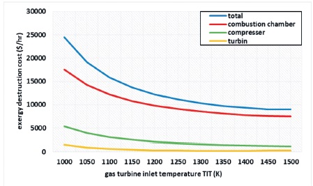
Figure 14. The Effects of Gas Turbine Inlet Temperature on the Exergy Destruction Cost for Each Component
Figure 15 represents the effects of gas turbine inlet temperature on the relative cost difference of each component of the gas turbine cycle. It is mostly not affected by gas turbine inlet temperature, with the maximum relative cost difference coming from the gas turbine, followed by the air compressor.
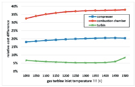
Figure 15. The Effects of Gas Turbine Inlet Temperature on the Relative Cost Difference for Each Component
Figure 16 conveys the effects of gas turbine inlet temperature on the energy economic factor of each component of the gas turbine cycle. Here, the exergy economic factor of the main components is mostly not affected by gas turbine inlet temperature, with the maximum exergy economic factor coming from the gas turbine, followed by the air compressor.
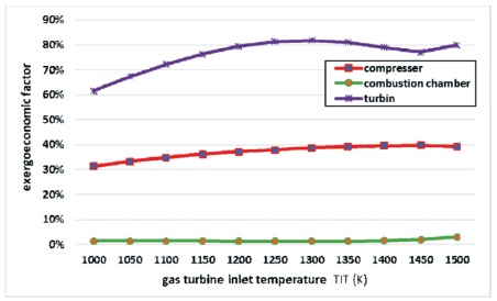
Figure 16. Effects of Gas Turbine Inlet Temperature on the Exergoeconomic Factor for Each Component
The values for cost flow in the bar chart of Figure 17 are for the cost flow of each component of the gas turbine cycle: the inlet compressor, outlet compressor, inlet turbine, outlet turbine, compressor power, net power, and fuel. The maximum cost flow rate is recorded for the inlet turbine, while the minimum value is for the outlet turbine.
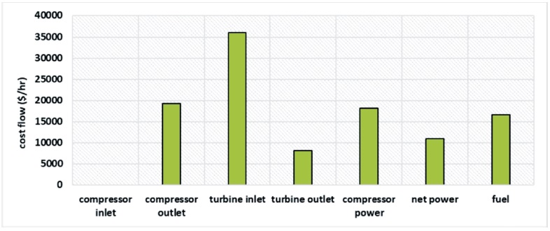
Figure 17. Cost Flow for Each State
Figures 18 depicts the relative cost difference, exergoeconomic factor each component, revealing that the combustion chamber in the plant has the highest exergy improvement and exergy destruction efficiency of 91 and 85%, respectively.
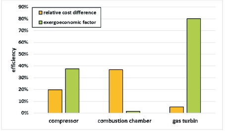
Figure 18. Relative Cost Difference and Exergoeconomic Factor
Figure 19 depicts the effectiveness of each component, with the combustion chamber outperforming the compressor and gas turbines.
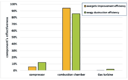
Figure 19. Component’s Effectiveness for Each Component
In this paper, the exergy and exergoeconomic analyses were applied to a case study gas turbine power plant in this paper. The researchers succeeded in obtaining the thermodynamic properties by employing MINI-REFPROP, Excel, and the MATLAB library tools box. Mathematical models were developed and presented regarding the mass, energy, exergy, and economy of the working power plant. Thermal and exergoeconomic analyses are employed, yielding useful economic status benchmarks. This paper succeeded in implementing the specific exergy costing approach to achieve the exergoeconomic factor, total cost of exergy loss, and average cost per unit exergy for the final products of the plant.
The parametric study was conducted, considering the effects of the gas turbine inlet temperature, air compressor inlet temperature, and compressor pressure ratio. For the considered case study status, the combustion chamber in the plant revealed the highest amount of energy destruction (85%), leading to the recommendation that more attention be paid to boilers in terms of design, selection, operation, and maintenance, while the combustion chamber has a high improvement potential of 91%.
The effects of gas turbine inlet temperature on the cost flow of the inlet turbine and compressor are presented. The cost flow of the inlet turbine and compressor decreases from 72000 to 29000 $/hr and from 65000 to 15000 $/hr, respectively, with the increase in gas turbine inlet temperature from 1000 to 1500 K. The contribution and the variation in the cost of energy destruction with load is lower.