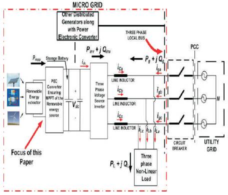
Figure 1. Typical configuration of a renewable energy fed three-phase microgid.
The three phase inverter is proposed to control the active and reactive power flow from the renewable energy source to a three phase generalized micro grid system. The proposed control system not only controls the grid power flow but also reduces the grid current total harmonic distortion in the presence of typical nonlinear loads. The control system shapes the grid current taking into account the grid voltage unbalance, harmonics as well as unbalance in line side inductors. The stability of the control system is ensured by the direct method of Lyapunov. SRC (Spatial Repetitive Controller) is also proposed to improve the performance of the current controller by estimating the periodic disturbances of the system. The proposed control system (implemented digitally) provides superior performance over the conventional multiple proportional integral and proportional resonant control methods. A new inverter modelling technique is also presented to take care of unbalances both in grid voltages and line side inductors.
Electrical power systems are getting more and more stressed due to the increase in power demand, limitation on power delivery capability of the grid, complications in building new transmission-distribution infrastructures and finally all these lead to blackouts[1]. Development of Power Electronic Converters (PECs) along with its highperformance controllers make it possible to integrate different types of renewable energy sources to the microgrid. Different converter topologies as well as control methods are surveyed in detail in [2]– [24] to integrate renewable energy sources, i.e., wind power and solar power, etc., in the power grid. In the cited papers, it can be seen that extensive research is undertaken to connect renewable energy sources to three-phase grids using threephase Pulse Width Modulated (PWM) inverters. Three-phase unbalanced grid interfaces of the microgrid systems are well documented in [21]– [24]. In[21] and [22], a hybrid series-parallel compensator is proposed to minimize the current harmonics generation effect in a typical unbalanced three phase microgrid system. Development of power electronic converters (PECs) along with its high performance controllers makes it possible to integrate different types of renewable energy sources to the micro grid. Grid-connected three-phase inverters are well documented in the literature [2]– [9] to facilitate renewable energy usage globally. The most popular topology is Current Controller VSI (CCVSI) mode to control the active and reactive power flow of the grid as reported in [3]. A detailed literature survey on the power control methodologies to take care of the different power quality issues related to unbalance grid interfaced through three-phase renewable energy source-based microgrid inverter is reported in [25]. It is also discussed in [25] that high bandwidth grid active and reactive power flow control and unbalanced grid current shaping are facilitated by directly controlling the currents of the CCVSI system.
Figure 1 shows the schematic of a typical three-phase multi-bus microgrid [10]– [24] system connected to the utility grid at the PCC. Different distributed generators interface to the microgrid and the load using PECs. The focus of this paper is on the three- phase inverter interfacing the renewable energy sources to the Local Bus of the microgrid in the presence of local loads as highlighted in Figure 1. It can also be noticed that the targeted renewable energy source-based inverter is connected at the three-phase local bus directly using a set of line side inductors (choke coil). At the same local bus, a three-phase nonlinear load is also connected. The nonlinear load draws non-sinusoidal current from the local bus. As discussed in [17], [18], the PEC extracts power from the renewable energy sources (may be solar, wind, or fuel cell- based energy harvester) at maximum power point operation. The output of the PEC is connected to an energy storage device such as battery, which is connected to the inverter dc link. The VSI operates in CCVSI mode to have flexible power flow control through the inverter.
Figure 1. Typical configuration of a renewable energy fed three-phase microgid.
The three-phase local bus voltage is referred to as grid voltage Vga , Vgb , and Vgc with respect to the utility grid neutral N as shown in Figure 2. It can be understood that the PEC converter extracts maximum power Pmpp from the renewable energy source. The load draws average active power PL and average reactive power QL from the grid (i.e., complex load power, SL = PL + jQL). The total load active power is shared by the grid average active power Pg and the average active power provided by the inverter Pinv. The inverter active power flow is controlled in such a way that, when the dc link battery is not fully charged, certain amount of active power Pbat = Pmpp − Pinv is pumped in to the battery. When the battery is fully charged, the full harvested power Pmpp is pumped out by the inverter to be utilized by the load and the grid. The CCVSI is controlled in such a way that the three-phase inverter currents (iCa , iCb , and iCc ) follow their corresponding references (as described in [25]) to ensure a specific grid power consumption along with maintaining the grid currents (iga , igb , and igc ) to be sinusoidal and drawing zero average reactive power from the grid. The CCVSI current references are calculated using p–q theory-based approach to ensure minimum low-frequency dc link voltage ripple to reduce the size of the electrolytic capacitor at the inverter dc link. The details of different current reference estimation methods are analysed. The present paper focuses on the current control methodology of the CCVSI.
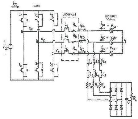
Figure 2. Simplified power circuit of the three-phase grid-connected renewable energy inverter
The basic grid-connected three-phase inverter topology is shown in Figure 1. The dc voltage source Vdc is assumed to be formed by the renewable energy sources as explained earlier in Figure 2. Considering the interconnection between the generalized grid and the inverter (Figure 2) and the isolation of grid neutral N with line side inductances are characterized with inductance and resistance, (La , Ra ), (Lb , Rb ), and (Lc , Rc ), the statespace equations for this system (states are: x1 = iCa and x2 = iCb ).
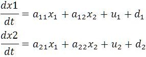
With control inputs
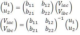
where, Vimn and Vgmn are the respective inverter and grid line voltages between phases m and n, respectively, with m, n ∈ a, b, c. Other coefficients are:
a11 = −((Ra Lb +Rc Lb +Ra Lc )/(La Lb +Lb Lc +Lc La ));
a12= −((Rc Lb −Rb Lc )/(La Lb + Lb Lc + Lc La );
a22 = −((Rb La + Rc La + Rb Lc )/(La Lb + Lb Lc + Lc La ));
a21 = (Rc La − Ra Lc )/(La Lb + Lb Lc +Lc La );
b11 = (Lb + Lc )/(La Lb + Lb Lc + Lc La );
b12 =−(Lc /(La Lb + Lb Lc + Lc La ));
b21 = −(Lc /(La Lb +Lb Lc +Lc La ));
b22 = (La + Lc )/(La Lb + Lb Lc + Lc La );
d1 =−(((Lb + Lc )vgac − Lc vgbc )/(La Lb + Lb Lc + Lc La );
d2 =−((−Lc vgac + (La + Lc )vgbc )/(La Lb +Lb Lc +Lc La ).
It should be added that d1 and d2 can be regarded as the disturbance inputs to the state equations shown in (1). In practical cases, the disturbance terms d1 and d2 in (1) consist of not only grid voltage disturbances but also unpredictable nonlinear periodic disturbances such as voltage drops due to inverter blanking time, etc.
It can be seen from (1) that the three-phase gridconnected inverter consists of two states, x1 and x2 . Thus, for arbitrary waveform tracking in these two states, a nonlinear control law is derived based on the Lyapunov function , i.e., the first principle of absolute stability. Considering the positive definite Lyapunov function as
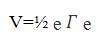
where error array e is represented as
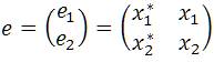
where x1 * and x2 * are the tracking references of x1 and x2 , respectively.
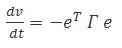
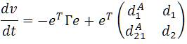
From Lyapunov function method of finding the stability, the first derivative should be a negative definite function as
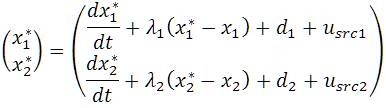
Performing derivative of (3) while using (1) and (5), the control variables can be solved as
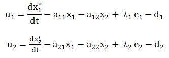
Thus, u1 and u2 as obtained in (6) are used as control signals for controlling the line currents of the CCVSI.
As explained in detail in [17], using voltage sensors, it is impossible to accurately estimate the disturbance terms d1 and d2 because of the associated in the voltage sensors and also the unpredictable nature of the disturbances due to different nonlinear phenomena in the inverter. If the estimates of the disturbance terms d 1 and d2 are different from its actual values, the control signals are affected accordingly. Using improper values of disturbance terms, the control laws in (6) are modified and used in (5) as
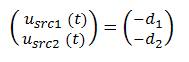
Thus,  is dependent on the difference of respective actual disturbance terms d1 and d2 . To ensure perfect current tracking, the two disturbance terms are estimated by the SRC based on the residual current errors as also reported in[17]. Following this analysis, the control laws in (6) are modified as
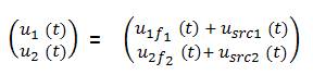
where, Lyapunov function-based control laws are represented as
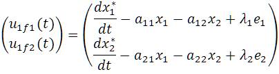
However, the disturbance terms are estimated using SRC [17] as
For a typical micro grid application, the grid voltage as well as inverter unpredictable non linearities do not change frequently, so the slow dynamics of SRC control laws are dominated by the fast dynamics of Lyapunov function control laws in the case of sudden change in current references. The details of the overall control system are shown in Figure 3.
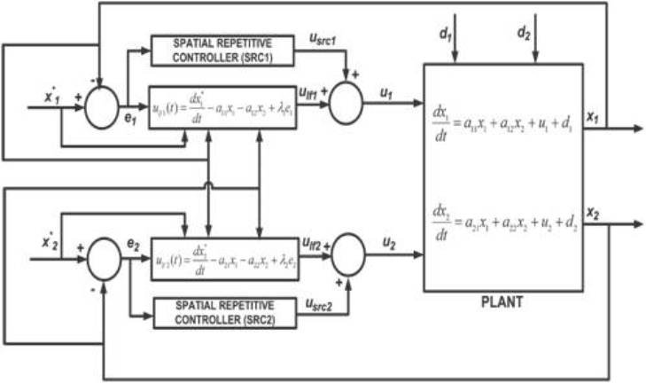
Figure 3. Schematics of overall control system
The stability of the overall system can be judged, by substituting (9) in (1) and the resulting state equations are as follows
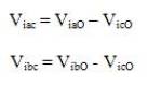
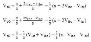
The control inputs u1 and u2 are found by using (6) and the line voltage references Viac and Vibc are calculated using (2) to track the reference inverter phase currents i*Ca and i*Cb. It can be understood that (6) and (2) provide constraint on the inverter line voltages Viac and Vibc, but there is no constraint on phase voltages of the inverter with respect to the dc link mid point O (as shown in Figure. 2). If the phase to dc link mid-point voltages (also called as pole voltages) of each phases of the inverter is called ViaO, VibO, and VicO for three phases, respectively. The inverter line voltages can be written in terms of inverter phase voltages as follows:
For three-phase generalized grid system, the following relation is considered:
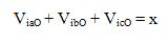
where x is a value provided so that each of the inverter phase is under the influence of similar voltage and current stress. This is facilitated to optimize the operation of each of the inverter legs. As mentioned before, control strategy does not put any constraint on each individual pole voltages but only on two of the line voltages.
Utilizing (14) in (13), the inverter phase to dc link mid-point voltage references can be calculated as:
In the case of sine PWM, the control signals for the upper switches (S1, S3, and S5) as shown in Figure 2 are given as:
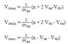
It can be remarked from (16) that, if x increases, each phase control signal value unnecessarily goes towards over modulation. Thus, for the present case of experimental study, x =0 is maintained.
The control system is shown in Figure 3 and the sampling Frequency fsample = 10kHz. The SPWM switching frequency is taken as fs = 10 kHz. The first time derivative terms in the control signals are replaced by its backward approximation rule. The Lyapunov function based control law portion for PWM (control input) at kth sampling instant can be written as
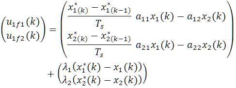
where Ts =1/fsample.
Both the SRC control law portion at kth position sample, θk and at ith iteration cycle, (implemented on fundamental grid phase θ as mentioned in [17] and [18]) [as can be referred to (11)] is implemented as
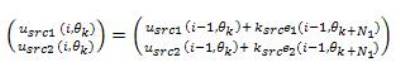
The parameters of both the SRCs are designed based on the transfer function analysis done in (12) and following the analysis already given in details in [17]. The design methodology is not further elaborated in this paper. The values of the parameters of the SRCs used are the gains, Ksrc = 100 (the value is calculated considering the convergence criterion of SRC as discussed in[17]) and the phase sample advancement, N1 =6. Figure 4 shows the implementation method of the proposed control. Figures 5(a), (b) and ( c) depict the simulation results.
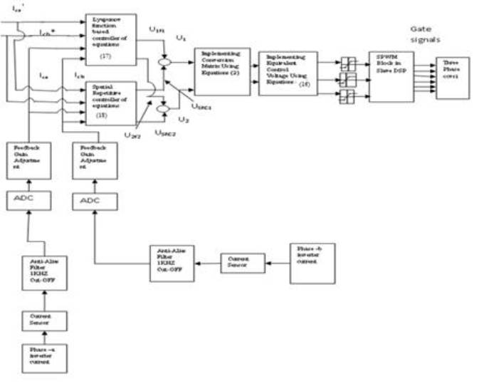
Figure 4. Details of the implementation method of the proposed control strategy
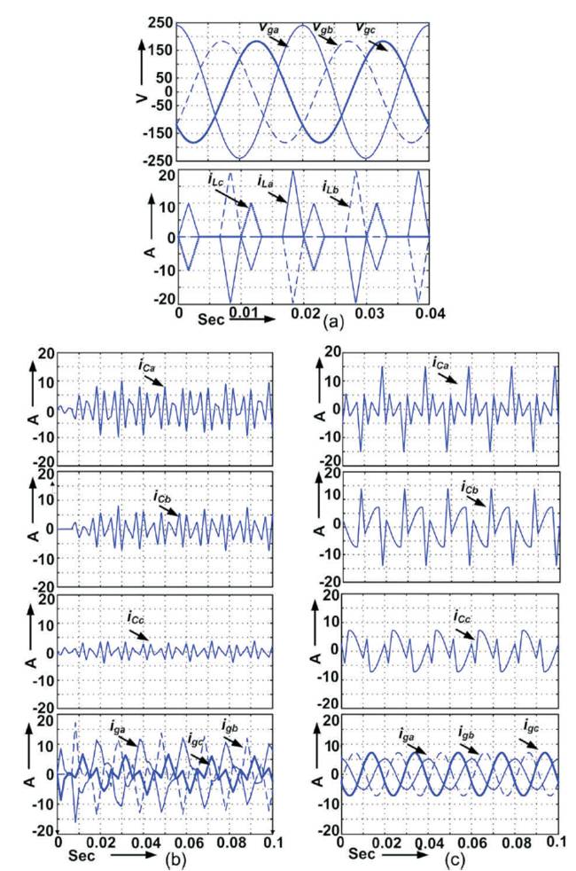
Figure 5. Simulation results. (a) Grid voltages, Vga, Vgb, and Vgc and load currents, iLa, iLb, and iLc. (b) CCVSI currents, iCa, iCb, and iCc and grid currents, iga, igb, and igc with traditional PI+fundamental frame cascaded PR controllers. (c) CCVSI currents, iCa, iCb, and iCc and grid currents, iga, igb, and igc with Lyapunov function-based controller, with unbalanced grid voltages.
The simulations of the power flow controller for grid connected renewable energy source were carried out using the Matlab/Simulink simulation package. Lyapunov function based current controller is capable of both active as well as reactive grid power flow control. Whereas, the traditional PI and fundamental frame cascaded PR controller-based system compensates only for active power. However, for a typical grid-connected inverter application, it is the normal to maintain grid side DPF =1 ensuring only active power flow control of grid while maintaining grid reactive as well as harmonic power flow to be zero.
A new current control strategy for a parallel connected three phase renewable energy source based inverter to connect to the generalized micro grid system is proposed. The control strategy is implemented directly in the a–b–c frame and is able to take care of unbalanced conditions in the grid voltage as well as line side inductances and load. The proposed method also reduces the THD (Total Harmonic Distortion) of the grid current along with the proper grid active as well as reactive power control.
The proposed control method is implemented in the digital controller and requires no Park's transformation block unlike the conventional method where multiple controllers are implemented in synchronously rotating dual reference frame and gives superior performance.
The proposed controller is also shown to be independent of grid frequency. The stability of the proposed control system is described with the help of Lyapunov's first principle, hence the name of the controller. A modeling method of the three phase grid connected inverter under unbalanced connection condition is also presented to facilitate the proposed control action.