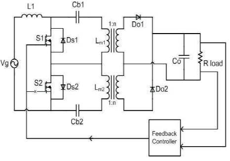
Figure 1. The proposed converter circuit
With the fast growing information technologies, high efficiency AC-DC front-end power supplies are becoming more and more desirable in all kinds of Distributed Power System Applications due to the energy conservation. However, the supply power factor in converters is low when output voltage is less than the maximum, as the firing angle is large. New recommendations and future standards have increased the interest in Power Factor Correction (PFC) circuits. For improving power quality in terms of PFC, reduced total harmonic distortion at input AC mains and precisely regulated dc output in buck, boost, buck–boost and multilevel modes are cascaded to convert. This paper introduces a closed loop isolated bridgeless AC to DC converter with high power factor and compares different closed loop controls. The Closed loop control strategies using PI, PID and Fuzzy Logic Controllers are compared with simulated results.
In Recent years, the demand for improving power quality of the AC system has become a great concern due to the rapidly increased number of electronic equipment. To reduce harmonic contamination in power lines and improve the transmission efficiency, Power Factor Correction (PFC) research became an active topic in power electronics, and significant efforts have been made on the developments of the PFC converters [1]. Most active PFC circuits as well as Switched Mode Power Supplies(SMPS) in the market today comprise a front-end bridge rectifier, followed by a high-frequency dc–dc converter such as a boost, a buck–boost, a Cuk, a Singleended Primary Inductance Converter (SEPIC), and a fly back converter [5]. This approach is suitable for a low-tomedium power range [2]. As the power level increases, the high conduction loss caused by the high forward voltage drop of the diode bridge begins to degrade the overall system efficiency, and the heat generated within the bridge rectifier may destroy the individual diodes. Hence, it becomes necessary to utilize a bridge rectifier with higher current-handling capability or heat-dissipating characteristics. This increases the size and cost of the device, which is unacceptable for an efficient design [4].
In an effort to improve the power supply efficiency, a number of bridgeless PFC circuit topologies have been proposed. All the presented bridgeless topologies so far implement a boost-type circuit configuration because of its low cost and its high performance in terms of efficiency, power factor, and simplicity[3]. The proposed DC converter due to its capability to step-down the output voltage with larger ratio and capable to isolate the input and output converter enhances the input current characteristic while retaining the isolation capability existed in Fly back converter.
This paper introduces a closed loop bridgeless PFC converter in which the feedback path contains Proportional Integral (PI), Controller or Proportional Integral Derivative (PID) Controller or Fuzzy Logic (FL) Controller [6]. The isolated transformer for smaller DC output voltage create an electrical isolation between the input and output side. It is obvious that in this converter, the diodes bridge rectifier and two sets of DC-DC converter are eliminated [7].
Figure 1 shows the schematic diagram of the proposed converter, the feedback controller block in the figure represents the PI, PID and FL controller and the response of the converter using three control techniques is compared.
Figure 1. The proposed converter circuit
In this paper, the proposed circuit is simulated for comparing the response of the converter in four cases in which one is open loop operation and the remaining three are closed loop operations using PI, PID and FL Controllers respectively. The proposed converter has two distinguish equivalent circuits during positive and negative half cycle; the operation during positive half cycle will be analyzed while the same analysis can be carried out for the negative part. Since low output power is our main concern for this converter, thus the Discontinuous Conduction Mode (DCM) is the best operating condition for this kind of power rating. Therefore, the Current injected Equivalent Circuit Approach (CIECA) is adopted to construct the steady-state and the smallsignal model of the proposed converter [9]. In CIECA method, the equations for current injected inwards and outwards the converter is identified within each switching period. These two current equations will then be perturbed and linearized to get the small signal equation for the control to output transfer function. This transfer function is vital in modeling the closed-loop control of the proposed converter. Furthermore, the steady state equation will be derived from the injected current equation obtained earlier [8]. The converter is depicted in Figure 2.
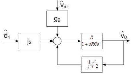
Figure 2. Block diagram of proposed converter
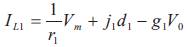
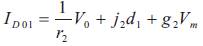
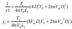
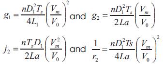
The input-to-output and control-to-output transfer functions of the converter are
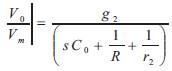
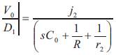
The control-to-output transfer function in equation (3) & equation (4) is used to design the closed-loop control of the proposed converter.
The desired output voltage and the obtained output voltages of the open loop AC to DC converter are compared and given to PI/PID/FL Controller to generate pulses of the switch. These pulses make the switch turn on and off with a high frequency.
A PI controller is a special case of the PID controller in which the Derivative (D) of the error is not used. PI controller forms control signal in the following way:
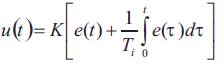
Ti- Integral time constant of PI controller. The controller output is given by
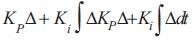
Where Δ is the error or deviation of actual measured value (PV) from the set point (SP) and Δ = SP - PV.
Without derivative action, a PI-controlled system is less responsive to real (non-noise) and relatively fast alterations in state and so the system will be slower to reach set point and slower to respond to perturbations than a well-tuned PID system.
A PID controller is a generic control loop feedback controller widely used in industrial control systems, a PID is the most commonly used feedback controller. A PID controller calculates an "error" value as the difference between a measured process variable and a desired set point. The controller attempts to minimize the error by adjusting the process control inputs. PID controller forms control signal in the following way:
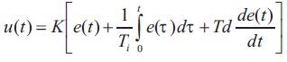
Where: Ki = K/Ti, Gain (reset) of integral part of the controller, and Kd = KTd, Gain of derivative part of the controller.
Derivative part of PID controller is proportional to the prognosis of error signal at time (t +Td), where Td is derivative time constant of the controller. Derivative mode reacts only on change of the controller input. Derivative mode improves stability of the system and enables increase in gain K and decrease in integral time constant Ti, which increases speed of the controller response. So, comparatively the response of the PID controller is faster than the PI Controller.
To tune in the parameters for the PI/PID controller can be a challenge, and if the time constants in the process are huge the time to do the optimization can be too long. But there are some rules lined out by Ziegler-Nichols. This method follows a given procedure.
The procedure is as follows:
If the output does not exhibit sustained oscillations for whatever value Kp may take, then this method does not apply.
Fuzzy logic theory is considered as a mathematical approach combining multi-valued logic, probability theory, and artificial intelligence to replicate the human approach in reaching the solution of a specific problem by using approximate reasoning to relate different data sets and to make decisions [10]. The performance of FL Controllers is well documented in the field of control theory since it provides robustness to dynamic system parameter variations as well as improved transient and steady state performances. FL controller is preferred over the conventional PI and PID controller because of its robustness to system parameter variations during operation and its simplicity of implementation.
The set of fuzzy control linguistic rules with 49 rules are given in Table 1. The inference mechanism of FL controller utilizes these rules to generate the required output.
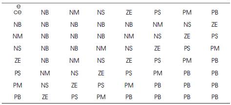
Table 1. 49 Linguistic Fuzzy rules
Fuzzification converts a crisp input signals, error (e), and Change in Error (ce) into fuzzified signals that can be identified by level of memberships in the fuzzy sets. The inference mechanism uses the collection of linguistic rules to convert the input conditions to fuzzified output. Finally, the defuzzification converts the fuzzified outputs to crisp control signals using the output membership function, which in the system acts as the changes in the control input (u).
In this section, the simulation results obtained using MATLAB/Simulink is presented. The key parameters used for the proposed converter are Input voltage Vg = 230Vrms, Inductor L1 = 150uH, Magnetizing Inductance Lm1 = Lm2 = 80uH, Capacitors Cb1 = Cb2 = 1uF, Desired Output Voltage 15VDC to 25VDC, Switching frequency fs = 50 kHZ, Output capacitor Co = 3.3mF, Transformer turns ratio n = 0.2.
The circuit is designed at very high frequency such that any change in the load made by the controller would not affect the input current waveform operating at line frequency. The state space large-signal model is developed. By closing the loop for the state-space model with PI or PID or FL Controller, the proposed circuit is simulated using closed loop conditions. The input current and input voltage waveforms of the state space largesignal model are depicted in Figure 3. It shows that the input current is in phase with the input voltage with sinusoidal waveform stating that the Power Factor is almost unity. As can be seen, the input current is reshaped such that it follows the sinusoidal wave-shape of the input voltage and in phase with it. The load is changed from 0.1s to 0.4s respectively is depicted in Figure 4.
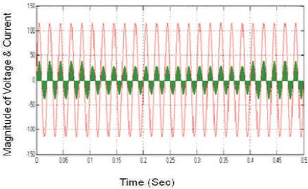
Figure 3. Source side Power Factor
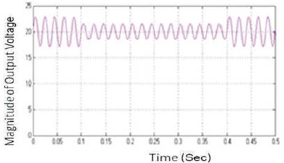
Figure 4. Output voltage waveform of State-space large signal model
The MATLAB/simulation is carried out in two cases:
Figure 5 shows, the output voltage of the open loop converter, a constant DC is observed from 0.5 sec and in open loop case; the converter is capable to regulate the desired output voltage within 0.5sec. Figure 6 shows the applied voltage and input current waveforms of open loop converter and closed loop converters using PI, PID, FL controllers respectively that indicates the supply side Power Factor.
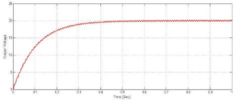
Figure 5. Constant Dc output voltage of open loop converter
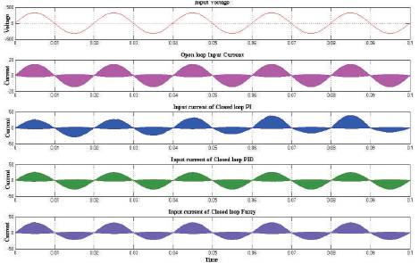
Figure 6. The Input Voltages & Output Currents
Figure 7 show the simulation results of the closed loop converter using FL, PID and PI controller respectively. The response of FL controller is far quicker than the other two controllers; the constant DC voltage is obtained within 0.005sec. In the same way when the PI and PID controllers are used in the feedback control system, the response using PI controller is obtained within 0.038sec and the response using PID controller is obtained within 0.027sec.
When the load changes, overshoot exist at the output voltage in which it tends to increase rapidly and it is observed at 0.3sec to 0.6sec. Even the load changes the input voltage and current are in phase that is depicted in Figure 7. The output voltage and output power responses, when the load changes are depicted in Figure 8.
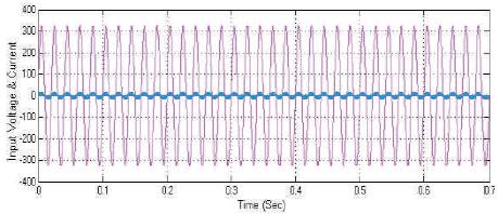
Figure 7. The Input power factor at various load changes
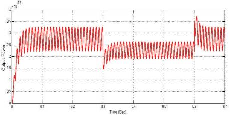
Figure 8. Change in Output Power for sudden change in load demand
In open loop cases, the converter is capable to regulate the desired output voltage in 0.5sec as observed in Figure 9, but in closed loop case the converter is designed such that it allows regulating the desired output voltage within 0.038sec using PI controller, 0.027 sec using PID controller and 0.005sec using FL controller as observed in the Figure 7.
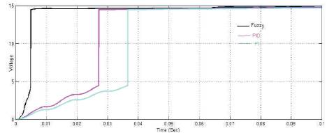
Figure 9. Comparision of responses of Closed loop converters using FL, PID and PI Controller respectively
The responses of the closed loop converter using the three controllers are compared and simulated as observed in the Figure 8, response observed by the converter using the PI controller in its feedback is within 0.038sec which is a quicker than the open loop converter's response that is 0.5sec, but the response of converter using the PID controller is observed within 0.027sec which is better than the response of the PI controller. Then the converter using the FL Controller in its feedback obtained quicker response than the other two controller that is within 0.005sec as observed in Figure 8 Therefore the camparision states that response obtained by the FL controoler is far quicker than the remaining ones.
This paper discusses a closed loop bridgeless PFC ac-dc converter is proposed and a comparative study. The large signal and steady-state model for the proposed bridgeless PFC converter are successfully developed, open loop and closed loop models are also simulated and further translated into simulation circuits to observe the converter capability to behave as a PFC circuit.
The models are used to design the required parameters of the converter operating in DCM condition. The steadystate operation of the proposed converter is determined to obtain the required components parameters. Then the closed-loop control is designed based on the large-signal model with PI, PID and FL controller and also the response time is compared with the open loop converter's response and the closed loop converter's response using the three controllers. It is shown that the designed FL controller is capable to regulate the desired output voltage from 15VDC to 25VDC in closed loop model with minimum settling time than that is obtained using the PI and PID controller, while the input current and voltage are in phase.
The authors would like to acknowledge the support, suggestion and encouragement rendered by B-Station, O&M, KTPS, APGENCO, Paloncha, in successful completion of this paper. One of the authors would also acknowledge gratefully the constant encouragement and continuous support by the Management & Principal of Institute of Aeronautical Engineering and St. Martins Engineering College, Hyderabad.