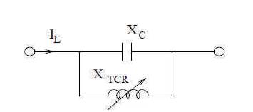
Figure 1. Equivalent Circuit of TCSC
In present days, increasing power demand leads to operate the transmission networks at their maximum operating limits. To overcome the problem of power flow control in a power system network, Thyristor Controlled Series Compensator (TCSC) is included. TCSC is one of the series compensating Flexible Alternating Current Transmission System (FACTS) devices; it consists of a series compensating capacitor shunted by a Thyristor Controlled Reactor (TCR). The main objective of TCSC is to provide partial continuously variable impedance by cancelling the effective compensating capacitance. The aim of this work is to improve the real power flow in the transmission line under different loading conditions and also simulation is carried out for different levels of compensation. In this work, performance analysis of electrical network using MATLAB Simulink and IEEE five bus system is carried out using Mi-Power tool.
In present days, interconnected power system operation and control faces the problem of power flow control and voltage instability. Every customer will always expect stable and reliable power from the utilities. To maintain the stability and reliability of the interconnected power system is a challenging task for the power system operators. In this direction, Flexible AC Transmission System (FACTS) devices will help to overcome the operational problems. The development of power electronics devices and their applications in power system helps in smooth controlling the power flow in transmission line, improve the power transfer capability limit of the line and reliability of the supply system.
The role of FACTS devices is to control the parameters of the transmission system such as series impedance and shunt impedances, current, voltage, phase angle, and damping oscillations at various frequencies below rated. As per IEEE, FACTS are defined as power electronics based system and other static equipment which has the ability to enhance controllability and increase power transfer capability. FACTS device can be connected either in series or parallel to the power system in order to provide the power compensation.
Benefits of using FACTS devices are as follows.
The FACTS devices are classified as,
(i) Series Controller
(a) Thyristor Controlled Series Capacitor (TCSC)
(b)Thyristor Switched Series Capacitor (TSSC)
(c)Thyristor Switched Series Reactor (TSSR)
(d)Thyristor Controlled Series Reactor (TCSR)
(ii) Shunt Controller
(a) Thyristor controlled Reactor (TCR)
(b)Thyristor Switched Reactor (TSR)
(c)Static Var Compensator (SVC)
(d) Static Synchronous Compensator (STATCOM)
(iii) Combined Controller
(a) Series- Series Controllers
(b) Series – Shunt Controllers
They can be effectively used to control the current and power flow in the system. The series controller consists of variable impedance such as capacitor or inductive reactor. The series controller is used to inject the voltage in series with transmission line. The injected series voltage in the line can be represented by variable impedance multiplied by the current flow through it. The series controllers supply or consume reactive power until the voltage is in phase quadrature with the line current.
They can be used for voltage control by supplying or receiving reactive or real power. These will inject current to the point where they are connected into the system. The variable shunt impedance of shunt controller will vary the current flow in the line by injecting a current into the system. The controller can add the reactive power, until the current is in quadrature with line voltage and adjust the real power, if the current is not in quadrature.
This controller has two configurations, one is series controllers operating in coordinated manner in a multi-line transmission system and the other configuration provides independent reactive power control, and at the same time, provides real power transfer through the power link.
This controller may have two configurations, one consists of two separate series and shunt controllers, that can operate in a coordinated manner and the other one being an interconnected series and shunt component. In each configuration, the shunt component injects a current into the system, while the series component injects a series voltage. When these two elements are unified, a real power can be exchanged between them via the power link.
In this paper, TCSC is used to enhance the power transfer capability of the transmission system. It has the following advantages.
In modern days due to increasing demand, transmission networks are overloaded and there is problem related to power flow control and voltage stability. In this paper (Kathal and Bhandakkar, 2013), SVC and TCSC are used for controlling power transfer in system. Performance of SVC and TCSC has been carried out on a 11-bus system using MATLAB and simulated results are compared for enhanced control of power flow. TCSC belongs to the FACTS family of devices. Flow of active and reactive power analysis through line is carried out by using TCSC. By changing the firing angle of thyristor TCSC, reactance can be varied. Study of different operating modes of TCSC is carried out (Patel and Bhatt, 2012). Present days, power acts as an essential part. However because of lacking resources, ecological elements for development of energy, the transmission is limited and also heavy loading of few transmission lines leads to instability – limiting factor. To damp out oscillation that occurs in transmission lines, TCSC is incorporated (Shankar et al., 2015). Utilizing controllers, power transfer through transmission system can be controlled. This can be accomplished by infusing voltage in series with the line. One of the conventional methods to achieve this is TCSC. Here, steady state model of TCSC and UPFC are considered for series compensation. The Newton- Raphson load flow equations are altered by the gadget parameters and the joined arrangement of equations and TCSC control equations are resolved for meeting of the formula (Choudhary et al., 2013). The FACTS controller improves power system performance. It provides optimal use of resources and it also helps in improving quality of supply. In this paper, development of TCSC is with open loop control system. TCSC characteristics and parameters are discussed and capacitive mode of operation of TCSC is simulated and implemented in MATLAB (Kumar, 2014). Today's power system is extremely complex and interconnected, as it contains more number of buses, generators, etc. Reliability and security has to be maintained for better utilization of power. As load centers are arranged far from power station, it is subjected to regulatory policies and environmental issue. The majority of losses are occurred at the transmission levels. So by controlling the transmission system with FACTS technology, losses can be reduced (Sekhar and Devi, 2016). To overcome steady state control problems in power system, FACTS controllers are being used. Here, total audit on the innovative work in the power network security improvement utilizing damping controllers are examined, and furthermore a few specialized issues identified with realities establishment have been highlighted, and execution examination of various FACTS controllers are compared (Rath et al., 2012). Simulation steps for MiPower tool is given in (FACTS DEVICES User Manual MiPower ). The concepts of FACTS Controllers in Power Transmission and Distribution system are discussed by Padiyar (2017). Many different techniques have been reported in the literature pertaining to investigating the effect of TCSC on power system stability (Chang and Chow, 1997; Chen et al., 1995; Lie et al., 1995).
TCSC usually connects in series with line and allows modifying power flows in the transmission line. It is a device consisting of a fixed series compensating capacitor with impedance -jX and shunt connected Thyristor Controlled c Reactor (TCR) with variable inductive impedance X (α). L Inductive reactance of the TCR can be controlled by controlling the firing angle a. This control is fast, efficient, and increases limits of transmitted power. Figure 1 shows the equivalent diagram of TCSC (Padiyar, 2007).
Figure 1. Equivalent Circuit of TCSC
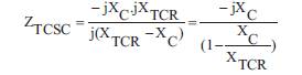
The TCSC is usually connected in series with the line. This will modify power flows in transmission line. Consider the equivalent circuit of the TCSC modelled as a capacitor in parallel with a variable inductor (as shown in Figure 1). The impedance of TCSC (Z ) is given by,
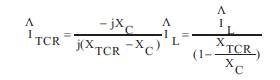
The current through the TCR (I ) is given by,
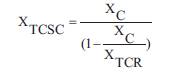
Since, the losses are neglected, the impedance of TCSC is purely reactive. Then, the above equation becomes,
TCSC can provide a continuous control of power transmitted over the transmission line. The different operating modes of TCSC are shown in Figure 2.
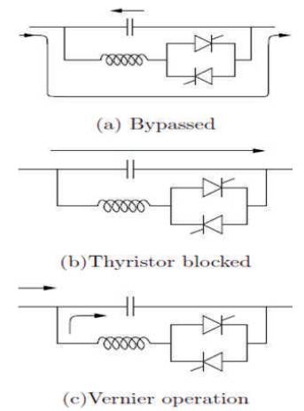
Figure 2. TCSC Modes of Operation
This mode is used mainly for protecting the capacitor against overvoltages. This mode is also termed as TSR (Thyristor Switched Reactor) mode. The thyristor valves are gated for 180 conduction and the current flow in the reactor is continuous and sinusoidal. The net reactance of the module is slightly inductive as the susceptance of the reactor is larger than that of the capacitor. During this mode, most of the line current is flowing through the reactor and thyristor valves, with some current flowing through the capacitor.
This mode is also termed as waiting mode. In this operating mode, no current flows through the valves with the blocking of gate pulses. Here, the TCSC reactance is same as that of the fixed capacitor and there is no difference in the performance of TCSC in this mode with that of a fixed capacitor. Hence, this operating mode is generally avoided.
In this operating mode, the thyristor valves are gated in the region of (
Figure 3 shows operating characteristics of TCSC. For inductive mode, value of a will be 0 - 49 , for resonance region, value of a is 49 - 69 and a for capacitive mode is 69 - 90 .
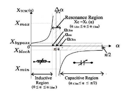
Figure 3. TCSC Operating Characteristics
Simulink model without TCSC shown in Figure 4 consists of a three phase voltage source, three phase Pi section lines, and load, for measurement purpose scope is added. Simulation is carried out and real and reactive powers are tabulated. Figure 5 represents Simulink model with TCSC.
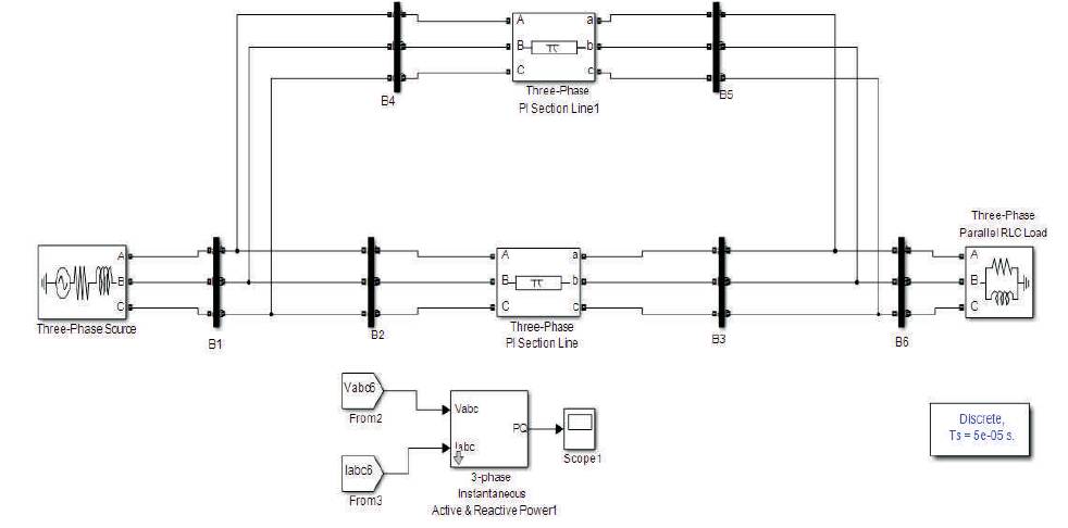
Figure 4. Electrical Network without TCSC
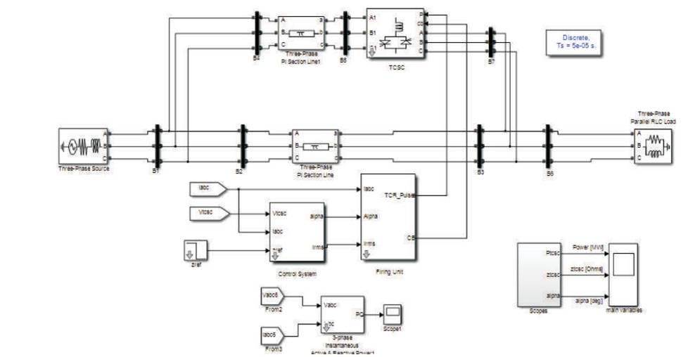
Figure 5. Simulink Model of Electrical Network with TCSC
Simulation model of electrical network is considered to show the performance of TCSC. It increases the power flow in existing transmission line. This power alter is obtained by varying the impedance of transmission line by changing the firing angle of installed TCSC device and there by regulates the power flow as required.
The degree of compensation is selected between 0.3 ≤ k ≤ 0.7. For different degree of compensations like 0.35, 0.45, 0.55, and 0.65 for different load conditions, the simulation is carried out and finally results are tabulated.
Real power and reactive power for different levels of compensation for line length of 100 km is shown in Table 1.
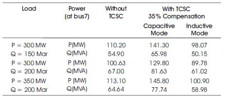
Table 1. For 35% Compensation
From Figure 6(a), (b) and (c), it can be observed that during capacitive mode of operation there is increase in the power flow on the line. During this mode, power is increased as a angle is reduced. Without TCSC real and reactive power was 110 MW and 55 MVAr, after connecting TCSC, it is increased to 141.30 MW and 65.98 MVAr.
From Figure 6(d), (e) and (f), it can be observed that during inductive mode of operation there is decrease in the power flow on the line. During this mode, power is reduced as a angle is increased. Without TCSC real and reactive power was 110 MW and 55 MVAr, after connecting TCSC, it is decreased to 98.07 MW and 50.15 MVAr.
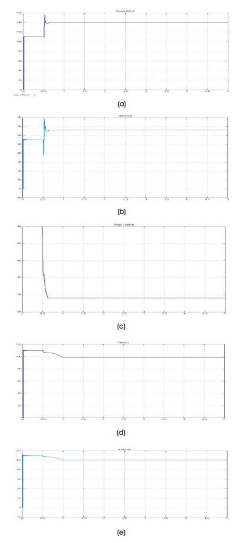
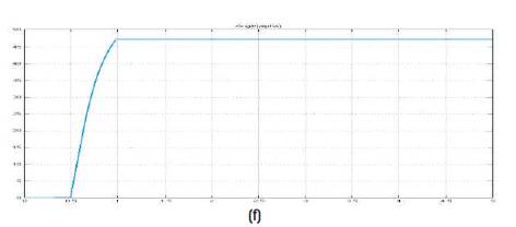
Fig 6. ( (f) Angle versus Time ure a) Real Power Versus Time, (b) Reactive Power Versus Time, (c) Angle versus Time, (d) Real Power versus Time, (e) Reactive Power versus Time, (f) Angle versus Time
From Figures 7 and 8, it can be seen that the real power increases as compensation level is increased, and reactive power decreases as compensation level is increased.
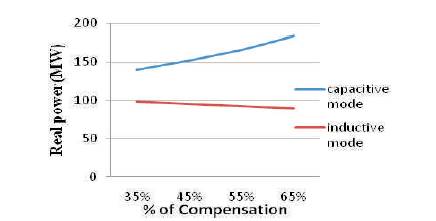
Figure 7. Real Power v/s % of Compensation
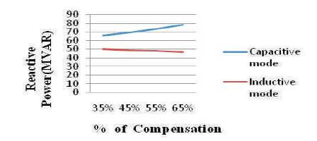
Figure 8. Reactive Power v/s % of Compensation
5-Bus system is represented with two generating units and seven lines as shown in Figure 9(a). Without TCSC (Figure 9(b)), the power flow through the line 3-4 was 19.38MW, and by incorporation of TCSC, the power flow through the line 3-4 is increased to 21 MW using MiPower simulation tool.
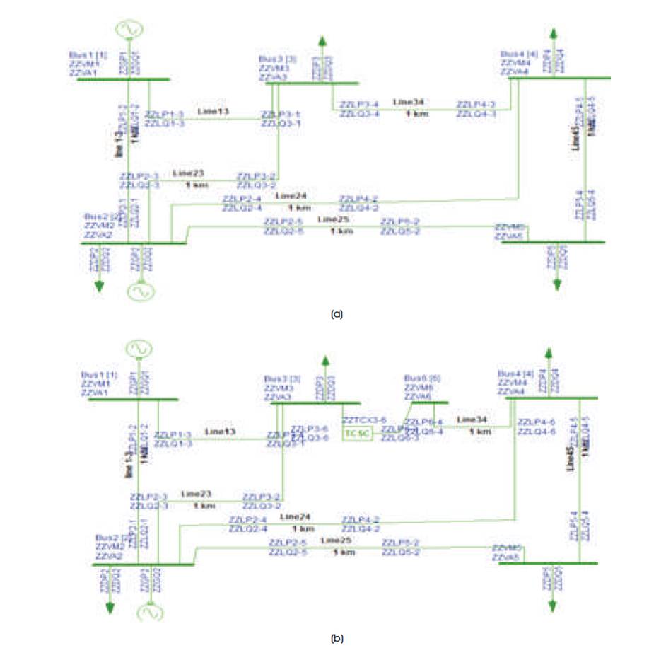
Figure 9. (a) 5 Bus System without TCSC, (b) 5 Bus System with TCSC
Bus voltages and powers without and with TCSC are given in Tables 2 and 3 respectively.
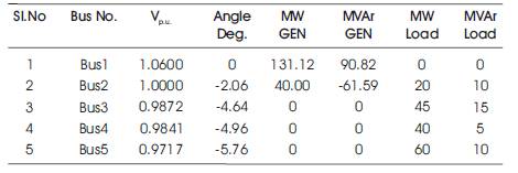
Table 2. Bus Voltages and Powers without TCSC
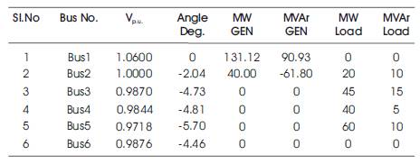
Table 3. Bus Voltages and Powers with TCSC
Case 1: Normal loading Condition (at Bus 4, P = 40 MW, Q = 5 MVAr and at Bus 5, P = 60 MW, Q = 10 MVAr), the line flows and line losses without and with TCSC are given in Table 4.
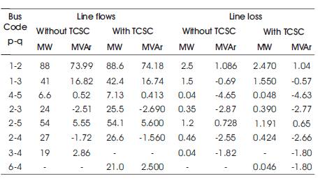
Table 4. Normal loading condition
From the load flow results, it can be observed that, without TCSC power flow between Bus 3 and Bus 4 was 19 MW and then after connecting TCSC, power is increased to 21 MW as shown in Table 5.
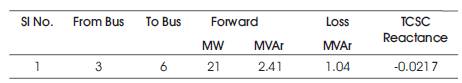
Table 5. Power Flow with TCSC
Case 2: For increased loading Condition (at Bus 4, P = 95 MW, Q = 20 MVAr and at Bus 5, P = 80 MW, Q = 25 MVAr), line flows and line losses without and with TCSC are given in Table 6. The bus voltages with and without TCSC for normal and increased loading condition is given in Table 7.
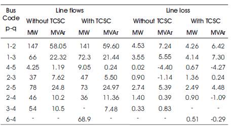
Table 6. Increased Loading Condition
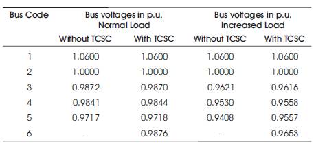
Table 7. Increased Loading Condition
The comparison of percentage of loadings of lines under normal and increased loading conditions with and without TCSC is shown in Table 8.
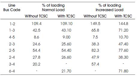
Table 8. Percentage of Loadings
In this paper, power transfer ability of existing transmission line is increased by incorporating a series capacitive compensation device such as TCSC. Simulation is carried out for different levels of compensations and different loading conditions. As level of compensation is increased, power transfer capability is increased. Results show that, during capacitive mode power flow will increase, whereas during inductive mode of operation, power flow will get reduced. Thus, using series compensation device such as TCSC provides smooth control of power flow in transmission line over large range.
