[1]
This paper presents the step by step procedure to evaluate Available Transfer Capability (ATC) of the interconnected transmission network using Power World Simulator. Fast and accurate determination of ATC is very important in real time. Various software packages have been developed to evaluate ATC of the given system. Also, there exist linear methods for ATC calculation, which are either based upon DC or AC Power Transfer Distribution Factors (PTDF). These are fast, but do not consider control changes such as generator reactive limits and voltage limits as the transfer limit increases. Another method to calculate ATC is Continuation Power Flow (CPF) method, which can produce accurate ATC values but requires repeated solution of power flow, and hence consumes more time. Also, there is a probabilistic approach to determine ATC, which is carried out by Monte Carlo Simulation. In this paper, PTDF method is explained to find ATC, which is implemented as Add Ons in Power World Simulator to compute ATC. The results are discussed for IEEE-14 bus system.
Deregulation of power system has resulted in many challenges in normal operation of system. Transmission lines are pushed to operate to their limits due to the increased demand and competition in electricity market (Patel and Girgis, 2011). In such a situation, it is important to ensure reliable operation of the system to provide consumers a quality and continuous supply. Evaluation of ATC gives an insight into a transmission system operator to transfer the power from producers to consumers reliably. It also provides necessary information for extending or installing new transmission lines.
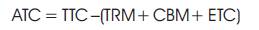
The maximum power which can be transferred from one area to another area is called as transfer capability corresponding to bilateral transaction under consideration. According to the NERC (North American Electric Reliability Council) definition, Available Transfer Capability (ATC) is the transfer capability remaining between two points above and beyond already committed transaction (Force, 1996). The ATC value between two points is given in equation (1).
where, TTC is total transfer capability between two points, TRM is transmission reliability margin, CBM is capacity benefit margin and ETC is existing transmission commitment including customer services between the same two points (Computation of Availability Transmission Capability). The diagrammatic representation of ATC definition is shown in Figure 1.

Figure 1. Basic Definition of ATC
In the literature, various number of methods have been proposed for evaluating ATC. These methods are classified as
Continuation methods in which the transfer capability is computed using repeated power flow (Ejebe et al., 1998). In this method, first load flow analysis is performed for base case, and solutions are obtained, then increment in the transaction is considered between source bus and sink bus, and again the load flow is performed. The process is continued until any line violates limit.
Optimal power flow approach is another method to formulate an optimization problem (Bhaskar and Jimoh, 2016; Sureban and Anakili, 2017). Equality constraints obtained from power flow are used in this approach. Security constraints such as line flow, voltage limits, and voltage instability conditions are considered as inequality constraints.
Linear methods use PTDFs (Power Flow Distribution Factors) which express the amount of power transfer that occurs on a particular transmission path during transaction between source area and sink area (Hojabri and Hizam, 2016).
PTDF is the fraction of a transaction from source bus 'm' to sink bus 'n' that flows over a transmission line from bus 'i' to bus 'j' (Manjure and Makram, 2003; Patra, 2015). The mathematical equation for obtaining PTDF is as given in equation (2).

where, X is the i row and m column element of bus reactance matrix also called as sensitivity matrix. x is the reactance of line joining bus i and j.
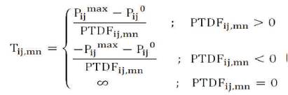
Above calculated PTDF is used to calculate transfer capability of a line i-j by using equation (3).
where,
P is the power limit of the transmission line between bus ij 'i' and 'j'.
P is the base case power flowing through the line ij between bus 'i' and 'j'.
The line having smallest T is the limiting line, which gives ij,mn the maximum power transfer. Thus, ATC between source bus 'm' and sink bus 'n' is obtained in equation (4).

Power World Simulator is a power system simulation software designed to perform various power system related analysis and operations. The software package is user-friendly and highly interactive and it is having graphical user interface, which makes it more convenient to use.
PWS consists of a number of integrated tools capable of efficiently solving systems of very large size of up to 100,000 buses. The Power World Simulator is a free standalone power flow analysis package. The base package of PWS contains all the tools necessary to perform integrated economic dispatch, area transaction economic analysis, Power Transfer Distribution Factor (PTDF) computation, short circuit analysis, and contingency analysis.
In addition to the features of the base simulator package, various add-on tools are available, including PV – QV curves analysis, Available Transfer Capability tool (ATC), Optimal Power Flow analysis tool (OPF), and so on.
The ATC add-on in Power World Simulator allows user to determine the maximum MW transfer possible between two parts which may be zones, areas or buses of the power system without violating security limits.
Simulator ATC utilizes advanced linearization methods by calculating PTDFs that allows user to calculate Available Transfer Capability very quickly, even during multiple contingencies and monitoring thousands of transmission lines and transformers.
Step 1: Model of the system for which ATC need to be calculated should be modeled by opening new case in File menu of PWS home page shown in Figure 2. While connecting transmission line, line limit of each line must be specified.
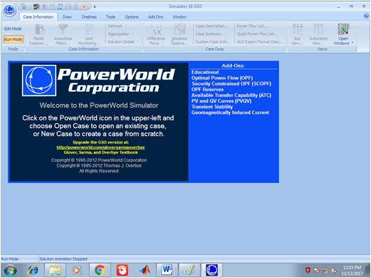
Figure 2. Power World Simulator Home Page
Step 2: After entering into Run mode, model must be solved to obtain base case solution.
Step 3: To open ATC, choose add-ons then Available Transfer Capability Tool, the ATC tool box shown in Figure 3 will be opened.
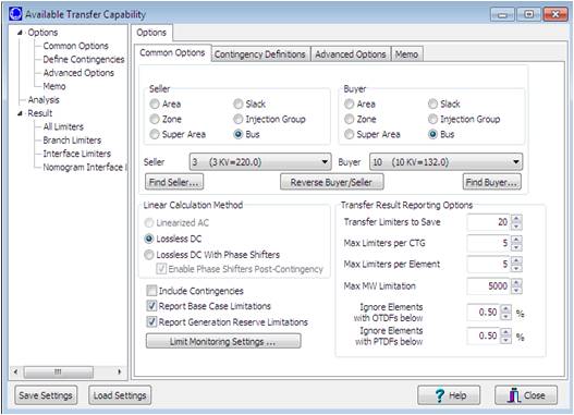
Figure 3. ATC Window
Step 4: There are three options in this window: Common options, Contingency definition, advanced options. In common options, user has to choose seller and sink bus/ area/ zone/ injection group.
Step 5: In this window, report base case limitations and report generator reserve limitations options need to be checked as shown in Figure 4. If it is required to include contingency, Include contingencies option need to be checked.
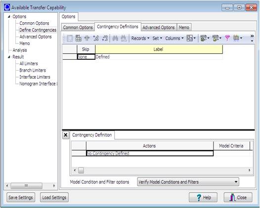
Figure 4. Contingency Definition Window
Step 6: After completing common options, contingency definition option is to be clicked to include contingency (only if include contingency option made checked in common option window). The window showed in Figure 4 will be displayed.
Step 7: By right clicking on 'none' block in this window, user will be able to define required contingency. After right clicking on none, 'insert special' option will be available. There, user has to opt for 'Auto insert contingency', then click 'Do insert contingency records' option. The window as shown in Figure 5 will be displayed.
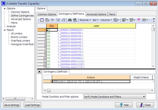
Figure 5. Contingency Record Window
Step 8: In advanced option window shown in Figure 6, user needs to select ATC Solution method. There are three methods available in PWS to calculate ATCs' such as Single Linear Step (SL), Iterated Linear step (IL), and then Full CTG solution.
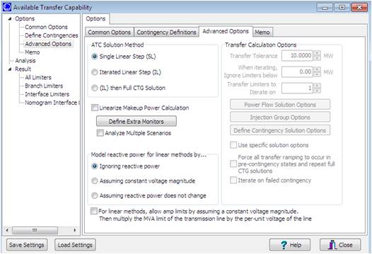
Figure 6. Advance option Window
Step 9: After choosing solution method, 'Analysis' option must be clicked and then start analysis. The window shown in Figure 7 will be opened.
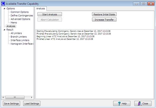
Figure 7. Analysis Window
Step 10: After analysis, 'Results' option need to be clicked to see transfer limits of all the lines for base case as well as for contingencies if defined earlier as shown in Figure 8.
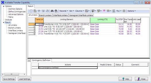
Figure 8. Result Window
Step 11: First column of this window will give transfer limits through the lines provided in second column. Third column values will give corresponding PTDF values.
Different combinations of source and sink bus are considered to estimate ATC under normal and contingency conditions for IEEE 14 bus system. The IEEE 14 bus system consists of 14 buses, 2 generators, 17 transmission lines and 3 transformers. The base case power flow analysis is carried out by considering bus one as slack bus. The transmission line series impedances and transformer details are on 100 MVA base. The line limits used for the system under study are given in Table 1.
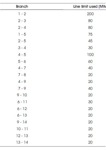
Table 1. Line Limit Used
The base case power flow analysis is carried out on IEEE 14 bus system by developing model as shown in Figure 9. The ATC is calculated by following the steps explained earlier. Table 2 gives the ATC values and corresponding PTDF for different transactions.
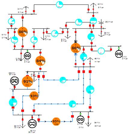
Figure 9. IEEE 14 Bus Simulated System
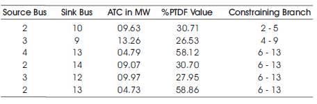
Table 2. ATC Values without Contingency
ATC is calculated with outage of line from bus 9 to bus 10 and from bus 10 to bus 11. During contingency simulator Outage Transfer Distribution Factor (OTDF) will be considered for calculating ATC. The results are shown in Tables 3 and 4.
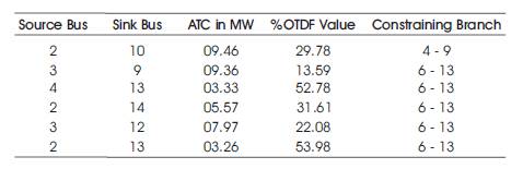
Table 3. ATC with Outage of Line 10 - 11
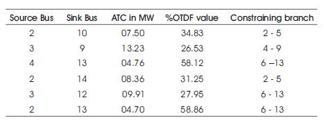
Table 4. ATC with Outage of Line 9 – 10
Figure 10 gives the comparison between ATC values with and without contingency of line 10 to 11. It can be observed from the figure that ATC values are reduced with line outage. ATC of transmission lines and also efficiency of transmission system with or without contingency can be increased by placing FACTS devices at optimal locations (Kumar and Kumar, 2013).
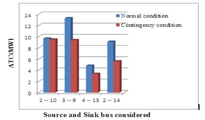
Figure 10. Comparison of ATC with and without Contingency
ATC calculation in real time will not only help in reliable operation of power system, it also Used helps in planning and control. Fast and accurate determination of ATC is very important in restructured market for efficient operation. In this paper, detailed steps for determining ATC using Power World Simulator is given and results are explained for IEEE 14 bus system. The proposed study further can be extended to find out the way to increase ATC and hence efficiency of transmission system.