[1]
This work propounds a totally distinctive heuristic technique kenned as Mesh-Elimination (M-E) technique for reconfiguring an Electrical Distribution System. System reconfiguration can also be utilized as the multi objective implemented to tackle utterly different issues like loss diminution, load equalization, and amenity restoration in electrical power systems. This paper introduces some proficient algorithmic rules predicated upon M-E technique to unravel the issue of loss diminution for an electric power distribution system that is given. The M-E strategy is also an appealing heuristic technique in terms of computations, accustomed to ascertain optimum layout of a radial distribution system that is given. The projected algorithmic rules are encrypted in MATLAB. To establish the legitimacy of this algorithm, it has been experimented with traditional IEEE Sixteen, Thirty-three and Sixty-nine bus systems, and the obtained outcomes are habituated to corroborate the potential of the projected algorithmic rules to being applied to various other systems.
Power system planner and operator's main aspiration is to produce, transport and distribute power with the uttermost feasible competence. Distribution systems are most indepth a part of the power system. They turn out a sizable amount of power losses as a result of low-voltage levels at which they operate. Apart from that, high (R/X) ratio additionally impacts the power losses. Recently, power systems across the globe were deregulated as a consequence of the competition among the vendors of electricity magnified systems. This leads to magnified complexness of distribution systems. Besides, the planners and operators of distribution system face new summons that places accentuation on price reduction and power quality improvement.
Most power distribution systems are designed to be radial i.e., to own only one path between every client and station. Radial systems have few benefits over meshed systems like lower short circuit currents, simpler switching, and protection apparatus. Besides, the radial layout furnishes lower global reliability. Hence, to utilize the advantages of radial layout, and concurrently to overthrow its hitches, distribution systems are excogitated and engineered as meshed systems; however, they function as radial systems.
They consist of 'n' range of feeders. Each and every feeder within an electrical distribution network features a totally divergent composition of industrial, residential and commercial sorts of loads and it's prominent that the day to day alterations of these load categories are completely unalike. As a result, the maximum load points on distinct feeders, substation transformers or on segments of feeder arise at totally divergent stages (nonconcomitant peaks). Continual analysis of the system is abundantly required so as to realize the target functions.
The radial layout of distribution systems is accomplished by inserting various sectionalizing switches within the system (notable as tie switches) accustomed to open the meshes that might otherwise exist. These switches, coupled with circuit breakers at the outset of every feeder are employed for reconfiguring the system, when required. Obviously, more the switches, more are the chances for reconfiguration and also higher are the efforts. Electrical Distribution Systems are orchestrated and designed not solely to cut back system investment cost but also operational cost.
The vigorous growth within the realm of microprocessors, micro-mini computers and telecom technologies renders us chances for a progressive management of power systems, explicitly, in the domain of distribution system computerization and mechanization. Paradigm distribution automation systems are presently being developed and tested on a small-scale basis exploiting the currently accessible data acquisition system. With the prelude to online adaptive control ability to the switches, management of configuration on-line has become an imperative area for automation of electrical distribution system. Intense analysis, development and demonstration efforts are presently being directed towards the machinery and computer aided programs to support large-scale distribution automation schemes for systemwide implementation by the electrical utility trade. A paramount operational complication in configuration management is system reconfiguration. Feeder/System reconfiguration is also used as a tool for planning in addition to a tool for real-time management of configuration.
The system analysis is concerned with the outcomes of the source and, branch currents and voltages, in a given network configuration. In this manner, the effective operation of the distribution system is accomplished by modifying its topological layout (i.e.) by closing or opening the tie and sectionalizing switches, in the course of all normal and maximum load conditions, for transferring the load from laboriously loaded feeders and station transformers to lightly loaded feeders and transformers. Similar transfers are effective not merely modifying the extent of the feeder loads being shifted. But also, in addition, it enhances the voltage profiles on the feeders and helps in effectual curtailment of losses in power systems. This methodology is termed as system reconfiguration.
In accordance with operational conditions, distribution system reconfiguration is classified into three types.
The Distribution Network Reconfiguration (DNR) complication is also conceptualized similarly to the task of recognizing a novel layout with negligible power misfortunes, whereas all system limitations are contented. Generally,
(i) To curtail the network's active power losses and improve dependability noted as Reconfiguration for diminution of losses
(ii) To extricate overloads inside the distribution system noted as Reconfiguration for balancing of the load
Rendering services to as many clients as accomplishable subsequent to an emergency situation, or throughout the outlined interruptions for its upkeep.
Therefore on reinforcement, the system dependability, efficiency and operational worth for incipient operational conditions are noted as reconfiguration for profit reconstruction /restoration of service. System Reconfiguration for loss diminution can withal be utilized as a part of designing studies to choose by which feeders the incipient clients are to be endowed.
To explain this system reconfiguration issue, Shirmohammadi and Hong (1989) used a heuristic technique that depends on the switches having the lowest current flow (sequential opening of switches method). During the 90's, progressive computation is in addition planned to resolve the issue of feeder reconfiguration.
Civanlar et al. (1988) has planned another heuristic method supported by the branch exchange technique. Later, Baran and Wu (1989) upgraded this method. An enhanced linear program with mixed integer has been conferred to figure out the optimal path in balanced large scale systems for minimal real power losses at moderate voltages.
Goswami and Basu (1992) had conferred an absolute technique for resolving meshed and radial distribution systems. Nevertheless, the foremost restriction to their technique is that no node within the system is the intersection point for over three branches, (i.e.) one incoming and a pair of outgoing branches.
Gomes et al. (2005; 2006) conferred a program supported by a heuristic methodology. The interpretation began with a meshed network acquired by means of shutting down all the tie switches. Later these switches are opened consecutively depending on an increase in the minimum power losses, decided by a load flow analysis. They conferred an optimum load flow-based outlook, throughout which the stature of the switch was delineated by continual functions to cut back the amount of load flows in it. Yet this technique could not have been the best because the power flow assessment should be executed throughout, which is tedious computationally.
Babu et al. (2007; 2008; 2013) had carried out the work for balancing of the load and restoration of service that in addition helped us in setting up heuristic rules in this work. The proposed technique is supported by a most effective power injection based power flow approach (Babu et al., 2010a), hence the technique is freelance of the complex power flows that existed in the literature.
In this paper, a very distinctive heuristic procedure referred to as mesh elimination strategy (Babu et al., 2010b) for loss diminishment is planned.
System reconfiguration is a non-linear hitch in character. A brute force and complex technique are applied to probe into all the practicable system configurations. Forbye, select any switch that optimizes the target variable to the extremes while satisfying the functional limits. Since an archetypal distribution system has several switches, a combinatorial optimization of every single conceivable alternative is not a handy extent in light of really long calculation time. The radiality constraint and distinct characteristics values of the switch avert the utilization of traditional optimization technique to unravel reconfiguration quandary.
So, the rumination about the empirical and domain expertise in conjunction with significant calculation skills are ought to obtain desired results for the operator in very less time.
The rudimental focus of system reconfiguration is to accomplish optimum configuration with minimum loss compared to the specified pristine system. There are several operational restrictions like capability constraint, voltage constraint, power losses, voltage drops, branch currents etc., in a distribution system that must be contended concurrently.
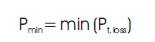
Diminution of total real power loss is contemplated as one among many goals for reconfiguring feeder and capacitor placement problems.
where, p is the aggregate real power loss in the system. And additionally every line segment connecting buses i and i+l has some definite power losses which may be mathematically formulated as in equation (2).
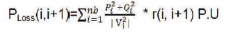
where,
P , Q = i bus real and reactive powers;
V = i bus voltage;
R(i,i+1) = resistance of line segment joining buses i and i+1; and
nb= number of branches.
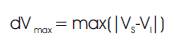
Reducing the maximal node voltage variation is taken into account as one more objective function for feeder reconfiguration and capacitance placement issues. The maximal variations of node voltages are computed as in equation (3).
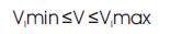
The magnitudes of voltages at each and every bus should be always kept within permissible limits as in equation (4).
The distribution feeders' current loading should always be a nominal current as in equation (5).
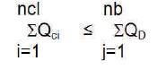
The aggregate wattless power of the capacitors placed should not surpass the overall system wattless power load as in equation (6).
No load should be omitted from the service and also the radial system layout should be maintained.
An incidence matrix denoted by (A) is used to demonstrate the radial constraint of a given network.
If ½A½=1 or -1, the system is said to be radial and =0, not radial.
There are two categories of switches in primary distribution systems.
The erstwhile switches are named as sectionalizing switches and the hindermost switches are alluded as tie switches. These switches are devised for ever y configuration management (to reconfigure the system) and protection (to isolate a fault). In the course of this paper, a list of algorithmic rules is framed to single out the most favourable switches that supply minimal power losses while not taking into consideration the entire candidate switches in the system.
Step 1:Scan the IEEE 16, 33 and 69 bus system statistics
Step 2: Execute the power flows for the given distribution system using Backward Sweep Method
Step 3:Evaluate the voltage magnitudes and real power losses at several buses.
Step 4:Estimate the variations in the voltages over all the tie switches (i.e., ΔV (i), for i=1, 2. . . N ). Here, N means the maximum number of tie switches
Step 5:Recognise the tie switches for which the deviation in voltage is the most and its code X (i.e., ΔV , max= ΔV (x))
Step 6:If the max ΔV > 0.01 (specified), move to 7 step tie or else, repudiate all shifting functions and move to 13 step
Step 7:Now, between any two buses, determine the minimum voltage variations of the tie switch X and note it as Vx
Step 8:Shut the tie switch X which forms a mesh and then a suitable sectionalizing switch Y adjoining Vx is opened. Later, the power losses are calculated and stored in PLoss y
Step 9:Instantly shut down the existing sectionalizing switch y, and the succeeding sectionalizing switch y+1 in this mesh is opened and now, determine the power loss and store it in as PLoss y+1
Step 10:If P - P < 0, the optimum switch to Loss y Loss y+1 eliminate the mesh can be sectionalizing switch Y, Otherwise, interchange (P , P ) move to 9 step
Step 11:If the count of iterations (n) is lower than or equal to the tie switch count (N ), increase the count as n=n+1 tie nd and move to 2 step to redo the program for the remaining tie switches
Step 12:Run the power flow program and simulate the results
Step 13:Terminate
The developed method has been encrypted in MATLAB R2013a model and is tested on conventional IEEE sixteen, IEEE thirty-three and IEEE sixty-nine bus systems. The initial alignment of conventional IEEE Sixteen, Thirty-three and Sixty-nine bus systems can be seen below along with their optimal configurations accompanied by a tabulated form of acquired outcomes. The voltage profiles of conventional and optimal cases for sixteen, thirty-three and sixty-nine bus systems can be seen in Appendix section.
A total of 28.7 MW active power and 5.9 MVAR reactive power are installed where, S =100 MVA and V =23 kV. base base For the standard configuration, the active power loss is about 477.57 kW. The switches S5, S11, S16 are considered as the tie switches (open) as shown in Figure 1. Post the system reconfiguration, the minimum loss configuration has the active power loss of about 202.95 kW. The voltage level improves the following reconfiguration. The switches S9, S11, S15 are opened for the loss minimum configuration as shown in Figure 2. The acquired outcomes are tabulated as in Table 1.
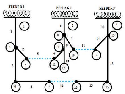
Figure 1. IEEE 16 Bus System Prior Reconfiguration
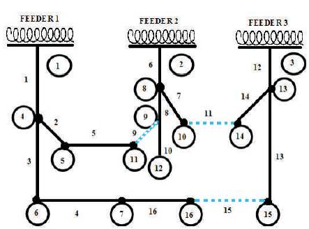
Figure 2. IEEE 16 Bus System Post Reconfiguration
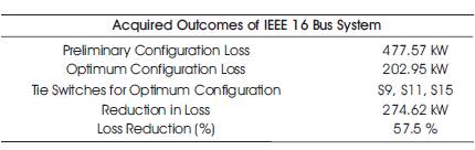
Table 1. Acquired Outcomes of IEEE 16 Bus System
A total of 3715 kW active power and 2300 kVAR reactive power are installed where, S =100 MVA and V base base =12.66kV. For the standard configuration, the active power loss is about 201.89 kW. The switches S33, S34, S35, S36, and S37 are considered as the tie switches (open) as shown in Figure 3. Post the system reconfiguration, the minimum loss configuration has the active power loss of about 128.41 kW. The voltage level improves. The switches S33, S9, S35, S36, and S25 are opened for the loss minimum configuration as shown in Figure 4. The acquired outcomes are tabulated as in Table 2.
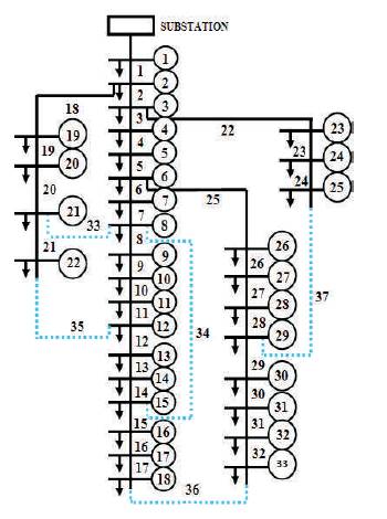
Figure 3. IEEE 33 Bus System Prior Reconfiguration
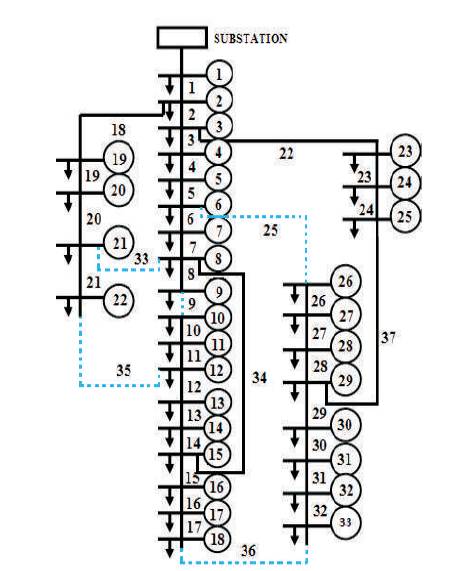
Figure 4. IEEE 33 Bus System Post Reconfiguration
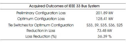
Table 2. Acquired Outcomes of IEEE 33 Bus System
A total of 3801.89 kW active power and 2694.1 kVAR reactive power are installed where, S =100 MVA and V =12.66 kV. For the standard configuration the active base power loss is about 224.55 kW. The switches S69, S70, S71, S72 and S73 are considered as the tie switches (open) as shown in Figure 5. Post the system reconfiguration, the minimum loss configuration has the active power loss of about 17.17 kW. The voltage level improves. The switches S69, S13, S71, S52 and S22 are opened for the loss minimum configuration as shown in Figure 6. The acquired outcomes are tabulated as in Table 3.
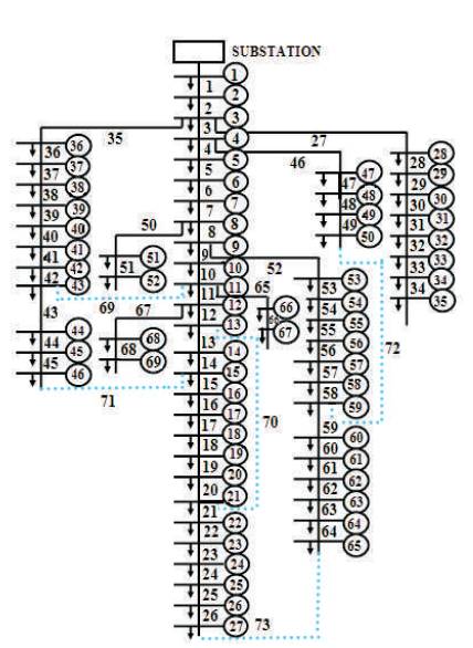
Figure 5. IEEE 69 Bus System Prior Reconfiguration
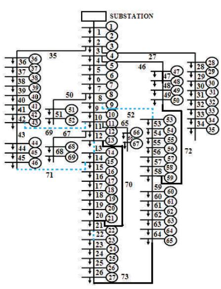
Figure 6. IEEE 69 Bus System Post Reconfiguration
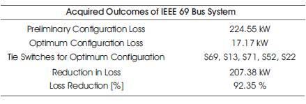
Table 3. Acquired Outcomes of IEEE 69 Bus System
Validation for the above results is done by comparing the results to results in Table 4.
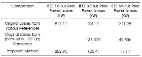
Table 4. Comparison of IEEE 16, 33 and 69 Bus Real Power Losses
In this paper, an exceptionally distinctive technique is projected to downsize the power losses along with enhancing the voltage profile in the systems by a costeffective power flow methodology. This algorithmic rule truncates the integrative switching drawback into a realizable one and abates the switch combos. The closed and open switches provide us with iterative combinations of switching and conjointly the simplest composition amongst them is found with fewer machine efforts. It's determined that these switch combos in each mesh of the system are so near to tie switch's lower potential. The algorithmic rule renders the optimal answer with little iteration within no time. Hence, the projected methodology could also be efficaciously employed in real-time implementations of huge distribution systems during highly loaded conditions.
The authors would like to express their profound Gratitude to the Principal and the Management of Sreenidhi Institute of Science and Technology, Hyderabad, India for their encouragement and support for the research work and also authors would like to extend their regards to Sreenidhi Institute of Science and Technology, Hyderabad, India.
The voltage profiles for prior and post-reconfiguration of the IEEE sixteen, thirty-three, and sixty-nine bus systems are seen in Figures A1, A2 and A3. It's that a giant improvement in the node voltages is detected after reconfiguring the conventional system with the M-E technique. The bus data for IEEE 16, 33 and 69 Bus Systems on which the test is conducted are given in Table A1, A2, A3.
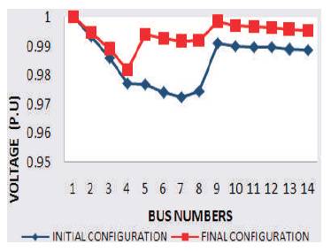
Figure A1. The Prior and Post Reconfiguration Voltage Profile of IEEE 16 Bus System
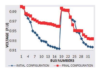
Figure A2. The Prior and Post Reconfiguration Voltage Profile of IEEE 33 Bus System
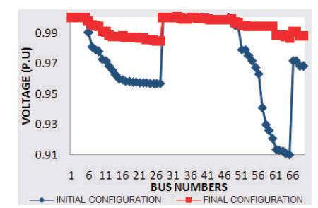
Figure A3. The Prior and Post Reconfiguration Voltage Profile of IEEE 69 Bus System
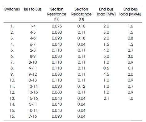
Table A1. IEEE 16 Bus System Data
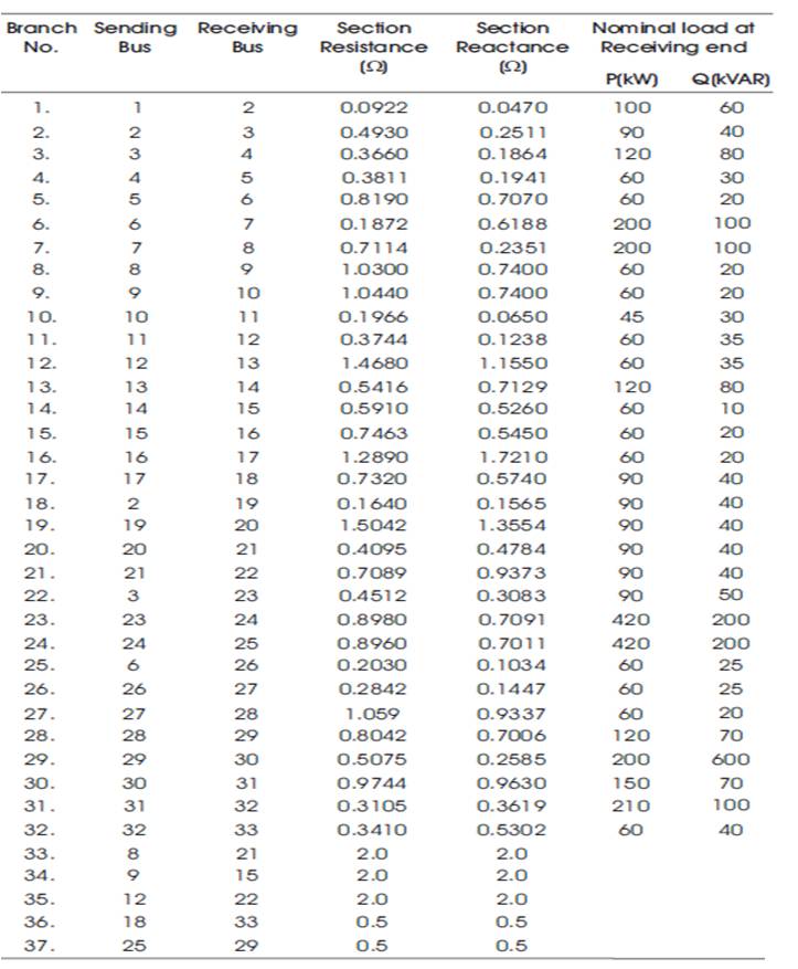
Table A2. IEEE 33 Bus System Data
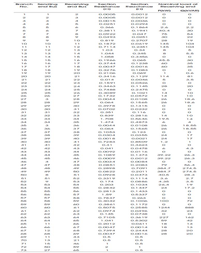
Table A3. IEEE 69 Bus System Data