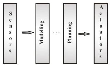
Figure 1. Information Flow
This paper addresses the problem of designing an autonomous robot for the purpose of navigating in the sensitive areas, keeping focus on localization of the robot. If a robot doesn't know its current location, it is very difficult to determine its further activities. Thus, localization plays a vital role in building an efficient mobile robot. This paper mainly focuses on design and implementation of OI-ROBOT (Object Identification Robot) which mainly comprises of fish eye lens camera to obtain Omni-directional vision, Sensors, to identify the position of the robot and an embedded micro controller that takes charge in target recognition and distortion rectification. The experimental results demonstrate the navigation and selflocalization of the mobile robot. This Robot also helps in fire detection and can be easily available through an Andriod phone or Internet.
Investigations on the navigation of mobile robots have been carried out to improve the autonomous navigation system, where localization is one of the crucial technologies. Localization is certainly needed for robots to efficiently carry out given tasks such as position estimation, direction guide, path planning, etc. Navigation without localization for robots reflects the same situation as people walking around with closed eyes without an aware of their current location and in which direction they have to move, thereby, localization plays a key role in the navigation of the mobile robots.
The main objective for an autonomous robot is that, it should be able to design its own path to the destination point and to localize itself in it. Path planning is considered an important issue because it allows a robot to navigate from a source point to a destination point. Earlier computer vision systems are designed with the concern of scene analysis. The scene analysis is about recognizing the activities in a scene and to assimilate information from the sequence of images. There are two kinds of scenes, one is local scene and the other is global. The ability of mobile robot to locate themselves in their environment is not only a fundamental problem but also an important requirement for some tasks such as navigation and mapping. In relative positioning, odometry and inertial navigation are commonly used to calculate the robot positions start from a reference point at a high updating rate. As the authors know that odometry is one of most popular internal sensors for position estimation as it is easy to use in real time. However the disadvantage of odometry is that it has an unbounded accumulation of errors. Therefore, frequent correction made from other sensors become necessary. In contrast, absolute positioning relies on detecting and recognizing different features in the robot environment in order for a mobile robot to reach a destination and implement specified tasks. Global scene allows robots to directly find its position through vision such as camera. Relocation is the problem in which a mobile robot has to estimate its pose only with a map of environment and measurements taken by vision without using any information of the initial pose.
An Autonomous mobile robot needs the capability to explore and navigate in dynamic or unknown environments in order to be useful in a wide range of industrial applications. In the past two decades, a number of different approaches have been proposed to develop flexible and efficient navigation systems for manufacturing industry, based on different sensor technologies such as odometry, laser scanners, inertial sensors, gyro, sonar and vision. However, since there is a huge uncertainty in the real world and no single sensor is perfect, it remains a great challenge today to build robust and intelligent navigation systems for mobile robots to operate in the real world. This paper describes a visionbased navigation method in an indoor environment for an autonomous mobile robot which can avoid obstacles. In this method, the self-localization of the robot is done with a model-based vision system, and a non-stop navigation is realized by a retroactive position correction system. Stationary obstacles are avoided with singlecamera vision and moving obstacles are detected with ultrasonic sensors.
Autonomy of robots depends on to what extent a robot relies on prior knowledge or information from the environment to accomplish its tasks. Robots can be divided into two classes of autonomy: Non-autonomous and Fully-autonomous robots.
These kinds of robots are completely steered remotely by the humans. The intelligence involved in these robots consist of interpreting the commands received from human controllers.
Robot vehicles are steered solely by the robots, themselves. The robots do not require human interaction to fulfill their tasks. Fully-Autonomous robot vehicles are capable of intelligent motion and action, without requiring any external guidance to follow.
Robot Navigation is the major task of an autonomous robot to move safely from one location to another. The general problems of navigation are formulated as follows.
The robot has to be aware of its current location in order to act as per the situations. Identifying the whereabouts of the robot is called robotic localization.
In order to accomplish a specific task, the robot has to know where it is going. It has to identify the destination point and this is called as target recognition.
Once if the robot is aware of its current location and its destination point, estimating a path to reach its target location is known as path planning.
In [1], the authors proposed a novel landmark- based particle localization algorithm in which two landmarks are used to localize the pose of robot. To achieve pose of the robot, their algorithm uses information on bearing angle and distance of landmarks. Computer simulations and experiments demonstrate the effectiveness of the proposed algorithm.
Geo referenced images help planners to compare and document the progress of underground construction sites. As underground positioning cannot rely on GPS/GNSS, in [2] a solely vision based localization method, that makes use of a texture-less 3D CAD model of the construction site was introduced. In OI-ROBOT analysis-by-synthesis approach, depth and normal fisheye images are rendered from pre-sampled positions and gradient orientations are extracted to build a high dimensional synthetic feature space. Acquired camera images are then matched to those features by using a robust distance metric and fast nearest neighbor search. In this manner, initial poses can be obtained on a laptop in real-time using concurrent processing and the graphics processing unit.
A novel Stereo Vision-Based Self-Localization System (SVBSLS) [3] for the RoboCup soccer humanoid league rules for the 2010 competition. To self-localize, the humanoid robot uses information from pan motors and stereo vision. This approach uses trigonometric functions to find coarse distance from robot to soccer ball and from robot to the landmark. For self-localization, this approach also uses relationship between humanoid robot and position of the landmark.
In [4], Radio-Frequency Identification (RFID)- based mobile robot localization which adopts RFID tags distributed in a space is proposed. Existing stand-alone RFID systems for mobile robot localization are hampered by many uncertainties. Therefore, they proposed a novel algorithm that improves the localization by fusing an RFID system with an ultrasonic sensor system. The proposed system partially removes the uncertainties of RFID systems by using distance data obtained from ultrasonic sensors. They defined a Global Position Estimation (GPE) process using an RFID system and a Local Environment Cognition (LEC) process using ultrasonic sensors.
A mobile robot localization in a dynamic environment by placing omni directional camera is proposed by Menegatti et al. [5]. Occlusion leads to wrong measurements which can be rectified by an Omni directional vision system, since it is emulating the range finder devices. They presented their results such as robot kidnapping, global localization and position tracking, not only in RoboCup environments but also in the corridors.
Haung et al. [6], used a mobile robot mounting with visual sensor to localize an unknown number of targets. To estimate the number of targets and their locations a recursive Bayesian filter over Random Finite Sets (RFSs) are used and the assumed robot position is known. The method is verified through real-world experimental trials, reliably detecting multiple targets and ignoring clutter obstacles.
Federico Thomas et. al [7] addressed the trilateration problem based on constructive geometric arguments instead of using numerical or algebraic methods for Robot Localization.
Leonard and Durrant-Whyte [8] formalized the basic algorithm for vehicle tracking problem using an Extended Kalman Filter (EKF) to match beacon observations to a navigation map for estimating the position of the mobile robot.
Thrun et al. [9] designed a learning algorithm, which enables a mobile robot to learn about best suited features/landmarks for localization. They also employed map matching [10], [11] by information from wheel encoders and wall orientation for localization of the robot.
The main objective of the proposed scheme is to overcome the computational problems in the field of robot localization. The OI-ROBOT presented in this paper is mainly comprised of a fish eye lens camera to obtain Omni-directional vision, Sensors -to identify the position of the robot and an embedded micro controller that takes charge in target recognition and distortion rectification. The OI-ROBOT framework is equipped with Hybrid approach for its mobility, IDCS (Integrated Design and Control Systems) and Tri-Color image recognition process.
In general, a mobile robot consists of a rechargeable battery with charging system, drivers, motion controllers, communication devices and visual based navigation subsystem. The OI-ROBOT presented in this paper consists of all the fundamental parts of AGV (Automated Guided Vehicles) with multiple sensors, network communication system and motion control system which are shown in Figure 1. These features of the OI-ROBOT facilitate its autonomous navigation without any physical connection with a system. Three functional elements that play a vital role in autonomous mobile robot are as follows
It provides the information regarding the position of the robot and environment round it.
Plans the future actions of the robot.
To perform the proposed actions of the planning system.
Based on these functional elements, a novel hybrid control architecture is shown in Figure 2, which is designed for mobile robots. The architecture mainly consists of four layers, primarily a sensor layer for information gathering. The second layer interprets the information gathered by the sensor based on three different modules stated as, Pose_estimate, Planner and Object_map. Pose_estimate (Position estimation) module is based on Kalman Filter state estimator [1, 2] that provides information about the robot’s position in the environment. Planner modules plan’s the direction of the robot. Object_map module identifies and reports information about the objects in the robots path. The third layer i.e., Exec-Layer consists of a navigation control module which changes the navigation path of robot when it detects an obstacle in its path. Finally, the ROBO-Interface layer enables the control of motors.
Figure 1. Information Flow
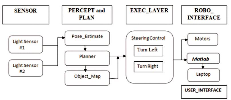
Figure 2. A Novel Hybrid Approach
Object detection plays a key role in autonomous mobile robots for which the system is embedded with an IP camera with fish-eye lens to retrieve a high quality image. The calibration of the fish-eye camera varies from perceptive camera calibration as the requisite incident angles should be greater than 90o.
When the distance of the object is Minimum, X0 = αx
When the distance is Maximum X0 = T tan ∈
Where X is the object, X0 is the height of the object, α is the magnification, T is the Optical system focus, and ∈ is the field angle. To focus widely, the process of image deformation and compression is introduced as curves as shown in Figure 3.
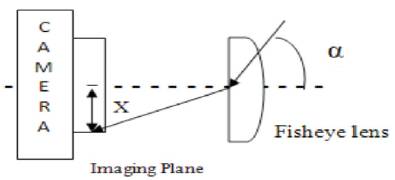
Figure 3. Image Distortion
These curves achieve image deformation up to certain point such that the solid angles could cover the estimated object space.
Let W = (A, B, C)k be a point in real world co-ordinates of the image, then the function, h(I, j)k maps the point at the K 2D image as, p = ( I, j) to p i.e. the calibrated position,
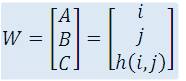
Let us assume that the fish eye lens is rotationally semetric, then the function is formulated as follows:
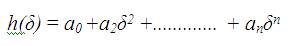
with,
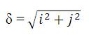
In the process of image rendering, the 3D object point is to be mapped on the image plane and this propagation is achieved by,

Where D is the distance from center of the image to projected point on plane.
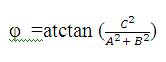
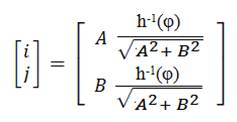
Then the temporary image co-ordinates are calculated as follows,
Object recognition in OI-ROBOT is facilitated by the concept of feature extraction where a desired vector feature is extracted from multiple features of the object. The main GUI of the MATLAB is configured to recognize the image based on Tri-color segment RGB (Red, Green and Blue). Autonomous navigation of the robot is based on the landmark and those landmarks are detected based on RGB. As if the robot moves away from the landmark, then the position of the landmark will be at the edge of the fisheye lens which causes severe distortion. This can be solved by arranging equidistant tricolor landmarks along the path of the OI-ROBOT.
The robot is supposed to estimate its current position from the initial state without human interference. The process is initiated by acquiring the images from fisheye lens IP cameras and extract the features from these images. These features are then compared with synthetic features with specific metric (landmarks). The following flowchart illustrates the steps involved in self-localization process. If the extracted features are harmonized with the specific metric, then the distance metric is calculated on analyzing the distance between the robot locality on the plane and the landmark position since the landmark is in rigid state. If the robot identifies any unspecified object on its path, then it turns left or right using its steering control options and reaches the landmark by capturing its surroundings. The process involved in object identification and robot localization is depicted in Figure 4.
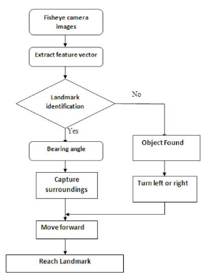
Figure 4. Object Identification and Self-Localization Mechanism
Navigation of the OI-ROBOT is controlled dynamically by capturing and processing the images based on the information like position and orientation of an object in the navigating path. The process of acquiring images is considered as a primary step in the vision based robotic system. MATLAB provides necessary support during the process of image acquisition.
In order to capture images through fish-eye lens camera, initially the video file of the target object is considered as an input. In the next step based of the video streaming, the OI-ROBOT tracks the object and isolates the colour of an object based on Tri-colour image recognition mechanism.
Figure 5 shows the main GUI of the MATLAB window to identify the object based on RGB. Here, the robot captures the video file of an object as input, and then it tracks the object to recognize the colour of the object. Finally, it generates the control signals based on which the robot gives the description about the colour of the particular object.
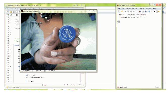
Figure 5. Main GUI of the MATLAB Window - Blue Color Recognized
Object identification using MATLAB based on RGB color mechanism can be used in the real world instances. For example, target identification in defence sector, mining caves, fire detection in sensitive areas, etc.
The presented object identification robot is equipped with enhanced feature of detecting fire accidents in sensitive areas. Figure 6 shows early fire detection method based on video processing. The basic idea behind fire detection is adopting an RGB model based on chromatic disorder measurement for extracting the fire pixels.
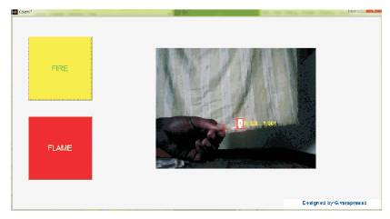
Figure 6. Fire Detection
Micro-controller is used to transmit control signals regarding the features of the object during navigation. The navigation of the OI-ROBOT from one landmark to another is shown in Figure 7. During its journey, if it encounters any obstacle, it automatically changes its path by itself. The experiments have proved that, the presented OI-ROBOT can be easily operated and controlled by using android operating system as a medium as shown in Figure 8.
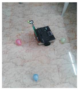
Figure 7. OI-ROBOT
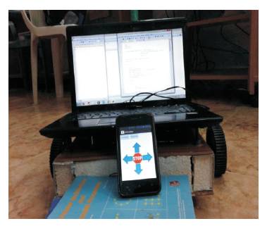
Figure 8. Robot-Android Interaction
Android phones have huge potential to exert as low cost robot controllers. The external interface is totally controlled by means of android based smart phone. The process involved in connecting a smart phone to a robot is as follows. Initially, the user will connect to a Bluetooth module using an SPP (Serial Port Profile) connection through the android based smart phone and the Bluetooth module connects to the robot controller. This process facilitates to transmit ASCII characters from phone to the micro-controller board upon which it turns on the motors based on the received control signals.
The presented OI-ROBOT is evaluated in terms of designing a user interface to work with windows operating systems. The main aim is to control the robot using the built-in Bluetooth function in windows OS and the external Bluetooth module that connects to the robot controller. Once it is connected it is possible to transmit ASCII characters from the windows desktop to the micro controller board as shown in Figure 9.
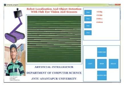
Figure 9. Robot-User Interaction with Computer
OI-ROBOT presented in this paper is also evaluated in terms of controlling the robot through Internet. To facilitate this process, the robot employs an "IP camera" to capture the surroundings and transmit the video to computer via the internet.
Initially, the user has to access the GPS module (Geographical Positioning System) that connects to the robot controller through internet. After the successful connection establishment, the communication between the user and robot takes place through HTTP or wifi. The user finally interacts with the robot using a RIA that relies heavily on HTML5, CSS3 and Java script. The communication layer interacts with the user to send commands. The Controller Layer is responsible for stopping the robot and starting the robot as required by the user's commands. Finally, as shown in Figure 10, the OI-ROBOT is successfully controlled and navigated through the internet.
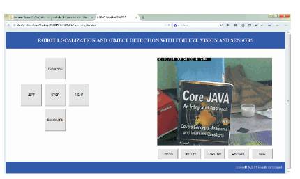
Figure 10. OI-ROBOT Controlled using Internet or Wifi
Unremitting improvement in the field of artificial intelligence leads to the design and development of the autonomous mobile robots. These kinds of robots are utilized to navigate in the sensitive locations even the places where a human cannot find a way. There are many areas in which these robots are used, ranging from "service robots" such as museum guides and "Defense robots" for rescue operations.
As a future work, this robot can identify human being using the face recognition techniques and also communicate with them. It can also be extended using NLP (Natural Language Processing) techniques for diverse language identification.