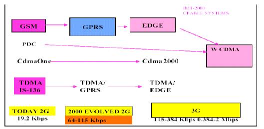
Figure 1. Evolution to IMT-2000/3G
UTRAN is one of the important subsystems in 3G / WCDMA architecture which connects the 3G mobile user to the WCDMA acting as a backbone for getting connectivity and user applications and also gives exposure to UTRAN nodes , their connectivity structure and the signal processing carried out by each part of the UTRAN system. Now-a-days, 3G, as considered in the world dictionary, this revolution gives a big market business throughout the world, which makes everything fast in the telecommunication field. This paper proposes a UTRAN architecture using WCDMA technology
The second generation systems were introduced in 1990s due to the incapability of first generation systems in meeting the telecom user’s requirements. But it has to be accepted that the limitations in 2G also pave way for the thinking on 3G. [10]. The limitations are
Sensing the need for higher data connectivity and video content, ITU (Iinternational Telecommunication Union) gave the proposal for 3G under the banner of IMT- 2000(International Mobile Telecom 2000) (Figure 1). The features of IMT-2000 are, it provides a future standard in which a single inexpensive mobile terminal can truly provide communications anytime and anywhere. There is a possibility of provisioning these services over a wide range of user densities and coverage areas (in building, urban , sub-urban, global). It enables the efficient use of radio spectrum consistent with providing service at an acceptable cost. IMT-2000 shall cover application areas presently provided by separate systems i.e cellular, cordless and paging etc. A high degree of commonality of design worldwide leads to a modular structure which will allow the system to grow in size and complexity. It is a Single unified standard (data & multimedia services). Across networks and technologies, seamless operation using a small packet terminal worldwide are performed. The High speed access of 144Kbps, 384Kbps and 2Mbps fast wireless access to internet supports full motion videophone with enhanced video quality, ubiquitous coverage and enable operators to provide service at reasonable cost.Thereby an orderly evolution path from 2G to 3G systems [1] protects investments. ITU initially proposed a single standard for 3G and has finally narrowed down technology options to the following five:
Figure 1. Evolution to IMT-2000/3G
While a multiplicity of 2G standards have been developed and deployed, the ITU wanted to avoid a similar situation to develop 3G. Hence, the ITU Radio communication Sector (ITU-R) has elaborated a framework for a global set of 3G standards, which will facilitate global roaming by operating in a common core spectrum and providing a migration path from all the major existing 2G technologies. The major 2G Radio access networks are based on either CDMA One or GSM technologies or different migration path is proposed for each of these technologies.
GSM can be upgraded for higher data rate upto 115 Kbps by deploying GPRS (General Packet Radio Service) network as shown in Figure 2. This requires the addition of two core modules SGSN (Serving GPRS Service Node) and GGSN (Gateway GPRS Service Node).GSM radio access network is connected to SGSN through suitable interfaces. GPRS phase-II will support higher data rates up to 384 Kbps by incorporating EDGE (Enhanced Data Rate for GSM Evolution). [9]
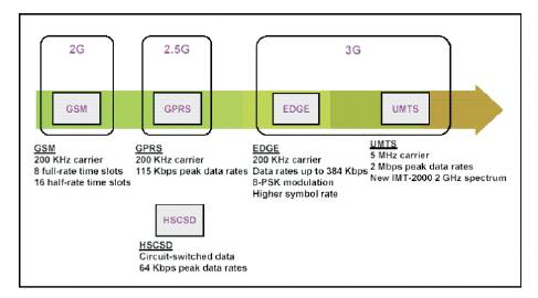
Figure 2. GSM to UMTS
EDGE is based on a new modulation scheme that allows a much higher bit rate across the air-interface called 8-PSK modulation. Since 8-PSK will be used for UMTS, network operators will be required to introduce this at some stage before migrating to 3G [2]. Further, to support data rates upto 2 Mbps, Third Generation radio access network (3G RAN) W-CDMA is deployed. 3G RAN is connected to the GSM MSC for circuit oriented services and to SGSN for packet oriented services (internet access). Therefore, the migration path can be represented as: GSM----GPRS--- EDGE--WCDMA.
WCDMA is a Wideband Direct-Sequence Code Division Multiple Access (DS-CDMA) system, i.e. user information bits are spread over a wide bandwidth by multiplying the user data with quasi-random bits (called chips) derived from CDMA spreading codes [7]. In order to support very high bit rates (up to 2 Mbps), the use of a variable spreading factor and multicode connections is supported. The chip rate of 3.84 Mbps leads to a carrier bandwidth of approximately 5 MHz. DSCDMA systems with a bandwidth of about 1 MHz, such as IS-95, are commonly referred to as narrowband CDMA systems. The inherently wide carrier bandwidth of WCDMA supports high user data rates and also has certain performance benefits, such as increased multipath diversity. WCDMA supports highly variable user data rates and the user data rate is kept constant during each 10 ms frame. However, the data capacity among the users can change from frame to frame. This fast radio capacity allocation will typically be controlled by the network to achieve optimum throughput for packet data services.
WCDMA supports basically two modes of operation: Frequency Division Duplex (FDD) and Time Division Duplex (TDD). In the FDD mode, separate 5 MHZ carrier frequencies are used for the uplink and downlink respectively, whereas in TDD, only 5 MHz is timeshared between the uplink and downlink. The TDD mode is based heavily on FDD mode concepts and was added in order to leverage the basic WCDMA system and also for the unpaired spectrum allocations of the ITU for the IMT-2000 systems. WCDMA supports the operation of asynchronous base stations, so that, unlike the Synchronous IS-95 system, there is no need for a global time reference such as a GPS. Deployment of indoor and micro base stations is easier when no GPS signal needs to be received. WCDMA employs coherent detection on uplink and downlink based on the use of pilot symbols or common pilot. While already used on the downlink in IS-95, the use of coherent detection on the uplink is new for public CDMA systems and will result in an overall increase of coverage and capacity on the uplink.
The WCDMA air interface has been crafted in such a way that advanced CDMA receiver concepts, such as multiuser detection and smart adaptive antennas, can be deployed by the network operator as a system option to increase capacity and/or coverage. In most second generation systems, no provision has been made for such receiver concepts and as a result, they are either not applicable or can be applied only under severe constraints with limited increases in performance. WCDMA is designed to be deployed in conjunction with GSM. Therefore, handovers between GSM and WCDMA are supported in order to be able to leverage the GSM coverage for the introduction of WCDMA. [5]
The UMTS system utilizes the same well-known architecture that has been used by all main second generation systems [6]. Functionally, the network elements are grouped into the Radio Access Network (RAN, UMTS Terrestrial RAN called UTRAN) that handles all radio-related functionality, and the Core Network, which is responsible for switching and routing calls and data connections to external networks. WCDMA Architecture is shown in Figure 3.
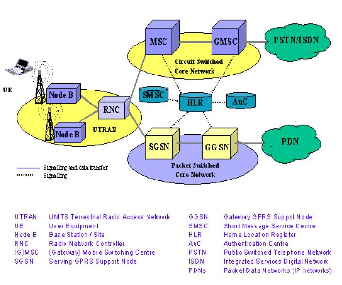
Figure 3. WCDMA architecture
The User Equipment (UE) and UTRAN consist of completely new protocols, the design of which is based on the needs of the new WCDMA radio technology [4]. On the contrary, the definition of Core Network (CN) is adopted from GSM. Figure 5 shows the UTRAN architecture. UTRAN consists of one or more Radio Network Subsystems (RNS). An RNS is a sub network within UTRAN and consists of one Radio Network Controller (RNC) and one or more Node Bs. RNCs may be connected to each other via an Iur interface. RNCs and Node Bs are connected with an Iub interface. The UE consists of two parts: The Mobile Equipment (ME) is the radio terminal used for radio communication over the Uu interface. The UMTS Subscriber Identity Module (USIM) is a smartcard that holds the subscriber identity, performs authentication algorithms, and stores authentication and encryption keys and some subscription information that is needed at the terminal.
The main function of the Node B (Base Station) is to perform the air interface L1 processing (channel coding and interleaving, rate adaptation, spreading, etc.) as depicted by Figure 4 and Figure 8. It also performs some basic Radio Resource Management operations such as the inner loop power control. It logically corresponds to the GSM Base Station. The enigmatic term ‘Node’ was initially adopted as a temporary term during the standardization process, but then never changed.
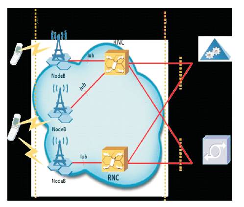
Figure 4. Node B in UMTS network
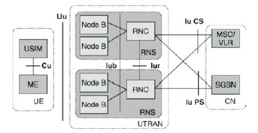
Figure 5. UTRAN Architecture
The Iu interface connects UTRAN to CN. Iu is an open interface that divides the system into radio-specific UTRAN and CN which handles switching, routing and service control. The Iu can have two main different instances, which are Iu CS (Iu Circuit Switched) for connecting UTRAN to Circuit Switched (CS) CN, and Iu PS (Iu Packet Switched) for connecting UTRAN to Packet Switched (PS) CN. The additional third instance of Iu, the Iu BC (Iu Broadcast), has been defined to support Cell Broadcast Services. Iu BC is used to connect UTRAN to the Broadcast domain of the Core Network.
While the UMTS radio interface, WCDMA, represented a bigger step in the radio access evolution from GSM networks, the UMTS core network [8] did not experience major changes in the 3GPP Release ‘99 specification. The Release ’99 structure was inherited from the GSM core network and, as stated earlier, both UTRAN and GERAN based radio access network connect to the same core network. [3]
The RNC (Radio Network Controller) is the network element responsible for the control of the radio resources of UTRAN. It interfaces the CN (normally to one MSC and one SGSN) and also terminates the RRC (Radio Resource Control) protocol that defines the messages and procedures between the mobile and UTRAN. It logically corresponds to the GSM BSC.
The RNC controlling one Node B (i.e. terminating the Iub interface towards the Node B) is indicated as the Controlling RNC (CRNC) of the Node B. The Controlling RNC is responsible for the load and congestion control of its own cells, and also executes the admission control and code allocation for new radio links to be established in those cells. In case one mobile–UTRAN connection uses resources from more than one RNS, the RNCs involved have two separate logical roles (with respect to this mobile– UTRAN connection).
The SRNC for one mobile is the RNC that terminates both the Iu link for the transport of user data and the corresponding RANAP signaling to/from the core network (this connection is referred to as the RANAP connection). The SRNC also terminates the Radio Resource Control Signaling which is the signaling protocol between the UE and UTRAN. It performs the L2 processing of the data to/from the radio interface. Basic Radio Resource Management operations, such as the mapping of Radio Access Bearer parameters into air interface transport channel parameters, the handover decision, and outer loop power control, are executed in the SRNC. The SRNC may also (but not always) be the CRNC of some Node B used by the mobile for connection with UTRAN. One UE connected to UTRAN has one and only one SRNC.
The DRNC is any RNC, other than the SRNC, that controls cells used by the mobile. If needed, the DRNC may perform macro diversity combining and splitting. The DRNC does not perform L2 processing of the user plane data, but routes the data transparently between the Iub and Iur interfaces, except when the UE is using a common or shared transport channel. One UE may have zero, one or more DRNCs. One physical RNC normally contains all the CRNC, SRNC and DRNC functionality.
Tight and fast power control is perhaps the most important aspect in WCDMA, in particular, on the uplink. Without it, a single overpowered mobile could block a whole cell. The following depicts the problem and the solution in the form of closed loop transmission power control. Mobile stations MS1 and MS2 operate within the same frequency, separable at the base station only by their respective spreading codes. It may happen that MS1 at the cell edge suffers a path loss, say 70 dB and above that of Ms2 which is near the base station BS, if there were no mechanism for MS1 and MS2 to be power-controlled to the same level at the base station.
Ms2 could easily overhunt MS1 and thus block a large part of the cell, giving rise to the so-called near–far problem of CDMA as shown in Figure 9. The optimum strategy in the sense of maximizing capacity is to equalize the received power per bit of all mobile stations at all times. While one can conceive open loop power control mechanisms that attempt to make a rough estimate of path loss by means of a downlink beacon signal, such a method would be far too inaccurate. The prime reason for this is that the fast fading is essentially uncorrelated between uplink and downlink, due to the large frequency separation of the uplink and downlink bands of the WCDMA FDD mode. Open loop power control is, however, used in WCDMA, but only to provide a coarse initial power setting of the mobile station at the beginning of a connection. The uplink and downlink frame structures are shown in Figure 6 and Figure 7 respectively.
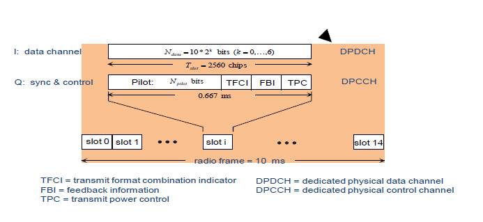
Figure 6. WCDMA uplink frame structure
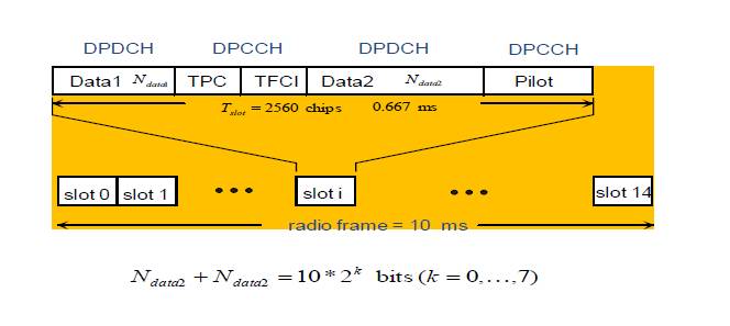
Figure 7. WCDMA downlink frame structure
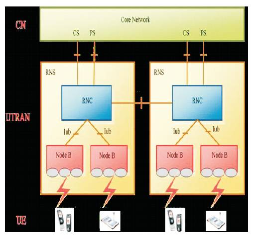
Figure 8. Node B architecture
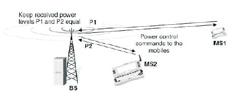
Figure 9. Power control
In closed loop power control in the uplink, the base station performs frequent estimates of the received Signal-to- Interference Ratio (SIR) and compares it to a target SIR. If the measured SIR is higher than the target SIR, the base station will command the mobile station to lower the power; if it is too low,it will command the mobile station to increase its power. This measure–command–react cycle is executed at a rate of 1500 times per second (1.5 kHz) for each mobile station and thus operates faster than any significant change of path loss could possibly happen and, indeed, even faster than the speed of fast Raleigh fading for low to moderate mobile speeds.
Thus, closed loop power control will prevent any power imbalance among all the uplink signals received at the base station. The same closed loop power control technique is also used on the downlink, though here the motivation is different: on the downlink, there is no near–far problem due to the one-to many scenarios. All the signals within one cell originate from one base station to all mobiles. It is, however, desirable to provide a marginal amount of additional power to mobile stations at the cell edge, as they suffer from increased other-cell interference. Also on the downlink a method of enhancing weak signals caused by Rayleigh fading with additional power is needed at low speeds when other error correcting methods based on interleaving and error correcting codes do not yet work effectively.
Practical observations are made by the way of viewing the existing configuration of UTRAN through OMCR (Operation And Maintainance Centre-Radio) and viewing the different events and processing outputs of different logs connected with UTRAN. All conclusions are getting through the node B as shown in Figure 10, and the RNC observations as shown in Figure 11, are calculated by giving the LAC (Location Area Code).
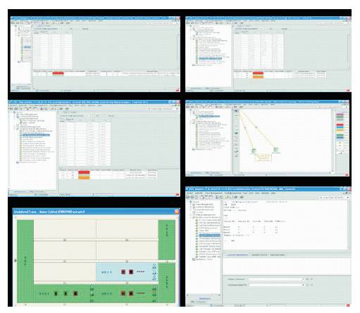
Figure 10. Node B screen shots
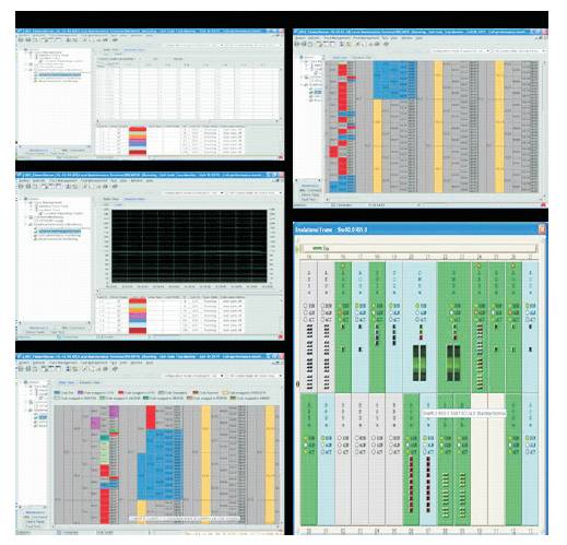
Figure 11. RNC screen shots
WCDMA technique is used for better data rate or bit rate (upto 2mbps). It can be used for high bandwidth as it provides bandwidth upto 5 MHz. It has signal carrier throughout the channel and provides higher security. The idea presented in this paper increases the capacity by a factor of 500 with regard to expected cellular deployments. By this means WCDMA technology has brought service evolution. The multi-technology approach of WCDMA provides better quality (eg. Video and sound), and improved personalization. In context of 4G systems, Software Defined Radio (SDR) will become an enabler for the aggregation of multi-standard pico/micro cells. For a manufacturer, this can be a powerful aid to provide multi-standard, multi-band equipment with reduced development effort and costs through simultaneous multi-channel processing.