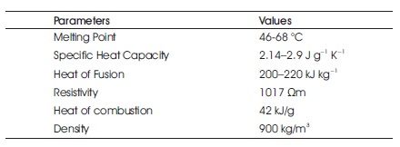
Table 1. Physical Properties of Paraffin Wax (Sundaram et al., 2015)
The world has lot of energy resources, but the major problem is concerned with its storage. This paper demonstrates the thermal energy storage using phase change material (PCM) which is one of the effective methods. In this paper, a 'two-way heat exchanger system' is designed in which thermal energy is stored and hot water can be utilized during daytime as well as night. The result of charging and discharging process of paraffin wax is observed. Basic working behind this system is to store the latent heat of paraffin wax. This heat can then be extracted to raise the temperature of water. The performance of PCM is compared with two different flow rates. This experimental result shows the feasibility of phase changing material as energy storage media.
The rapid increase in energy consumption around the world leads to a rise in greenhouse gases. It has a heavy environmental impact such as global warming, ozone layer depletion, etc. This increases the temperature of the earth, resulting in bad environmental condition for human beings. Scientists are concerned about rise in the day-today temperature. The difference between 1.5-2 °C of global warming brings a new in the climatic condition (Riebeek, 2010).
The non-renewable sources are limited only to a few decades in future and the prices of these fuels are getting high day-by-day. The future of the new energy sources is the one that can be used most of the time. Hence, it is necessary to switch our daily energy production to renewable energy sources. Renewable energy sources are solar, wind, tidal, biofuel which are available at a tremendous amount. Scientists all over the world are researching the steady production of power from solar energy. For the steady supply of solar power, the storage of solar energy is also important.
Energy savings and energy efficiency can be increased by an effective approach towards energy storage. Thermal energy storage is acknowledged as one of the important technologies for energy storage in the future. There are three major methods currently considered for thermal storage: latent heat, sensible heat, thermochemical energy. Latent heat energy in comparison to sensible heat energy is a more effective technique which has more storage capacity (Padmaraju et al., 2008).
A phase change material (PCM) is a substance with a high latent heat of fusion which, melts and solidify at a certain temperature, can store and release large amounts of energy (Sarbu & Sebarchievici, 2018). Heat is absorbed or released when the material changes from solid to liquid and vice versa. Thus, PCMs are classified as latent heat storage (LHS) units (Cárdenas & León, 2014).
Use of phase change material is an effective way of storing thermal energy and has advantages of high storage density due to its isothermal nature of energy storage (Cárdenas & León, 2014).
Three types of phase changes can happen in a material, i.e., solid liquid phase change, solid gas phase change, liquid gas phase change. Generally solid-gas phase change and liquid-gas phase change involves large amount of volume change, hence solid-liquid phase change is the most preferred mode of latent heat storage (Cárdenas & León, 2014).
A vertical shell and tube type storage system is a simple and effective way of storing thermal energy using phase change material.
Thermal energy storage is one of the effective ways to store energy. This study is focused on storing latent heat in the phase change material. The objective of this study is to design a shell and tube phase change material (PCM) based heat exchanger which acts as thermal energy storage and to examine the ability of phase change material to store latent heat.
Phase change materials are latent heat storage materials. As we give heat to PCM the chemical bonds within the PCM breaks up and this material changes its phase. Phase change is an endothermic process, therefore, PCM absorbs heat (Sharma & Sagara, 2005). The material starts to melt when the phase change temperature is reached. The temperature then remains constant until the melting process is finished. The heat stored during the phase change process (melting process) of the material is called latent heat (Vaivudh et al., 2006). The two main advantages of latent heat storage are,
There are many phase change materials that have been known to us for melting temperature and latent heat of fusion. Since there is not a single material that can have all the desired properly for thermal energy storage, we must use the material which is available and try to make adequate system (Khare et al., 2012).
Paraffin is a family of saturated hydrocarbon available in natural gas and petroleum. The general chemical formula of paraffin is CnH2n+1, where n indicates the number of carbon atoms present in the compound. This hydrocarbon is available in gaseous state when n≤ 5; when n is between 5 and 15 they are in liquid state and beyond that they are found as solids. Paraffin family of compounds are generally used as PCM for storing energy in applications like thermal energy storage (TES), sensible heat storage (SHS), Latent heat storage (LHS), chemical heat storage (CHS), etc. Paraffin used as PCMs are generally waxy solids and have range of melting points (Vakhshouri, 2019) between 25 °C to 67 °C (Thirugnanam & Marimuthu, 2013). Some of the physical properties of paraffin wax are listed in Table 1.
Table 1. Physical Properties of Paraffin Wax (Sundaram et al., 2015)
Amir Reza Vakhshouri states that paraffin waxes are safe, reliable, inexpensive, and non-irritating substances, relatively obtained in a wide range of temperatures. Considering the economic factors, most technical grade waxes can be used as PCMs in latent heat storage systems. Looking into the chemical factors, paraffin waxes are inactive and stable. Physically, they exhibit moderate volume changes (10–20%) during melting but have low vapor pressure (Cabeza et al., 2011; Vakhshouri, 2019). Considering the above factors, paraffin wax is selected as the experimental material for this study.
Paraffin wax has few advantages over other PCMs and they are high storage density and isothermal operation near phase change temperature and some of the disadvantages are low thermal conductivity, non compatibility with plastic containers and paraffin wax is moderately flammable (Thakare & Bhave, 2015). As the advantages weigh over the disadvantages and with the use of technological adjustments, paraffin wax is used for this study.
The actual setup of the thermal energy storage (TES) device without insulation is shown in Figure 1. The CAD-model of TES with double pipe/double fluid system is shown in Figure 2. Heat transfer fluid flows from red color pipe and water flows from the blue pipe. The actual setup of TES device with insulation is shown in Figure 3. The technical specifications of heat exchanger are shown in Table 2. Copper pipes are used to enhance the effective thermal conductivity of the system. A total of 25 copper tubes are used. 13 tubes are used for heat transfer fluid and water flows through 12 tubes. The shell is made up of stainless steel to reduce the heat losses during charging and discharging (Murray et al., 2011).
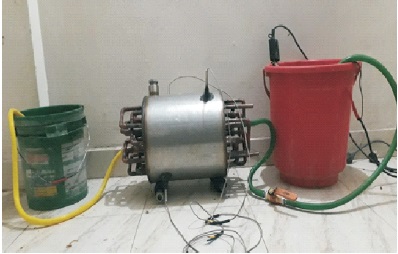
Figure 1. Actual Test Rig for Thermal Energy Storage Unit Before Insulation

Figure 2. Design of Thermal Energy Storage Device (CAD Model)
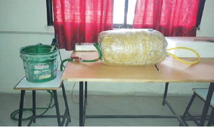
Figure 3. Actual Test Rig for Thermal Energy Storage Unit with Insulation
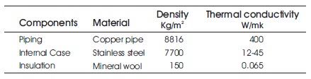
Table 2. Specification of Heat Exchanger (Engineerings Edge, n.d.)
The mineral wool is used as an insulator on outer side of the setup to reduce the heat losses. It forms a cylindrical structure. PCM of 15 kg is filled in the shell and outside area of tubes. Two thermocouples are used to measure the inlet and outlet temperature of the water as well as Heat Transfer Fluid (HTF). The melting point of paraffin wax is 67 oC. Therefore, we use water as heat transfer fluid. Two storage tanks are used to store inlet and outlet of water. Pump is used to pump the HTF in the TES device.
Heater is used to heat the HTF. Hot water at constant 80 0C is passing through copper tube to charge the PCM. Cold water is passed from another fluid flow system to extract the energy from PCM. The temperature of the water at inlet and outlet is measured by a thermocouple at an interval of five minute.
Tinlet = Inlet temperature of HTF and water
Toutlet = Outlet temperature of HTF and water
T2 and T3 = Temperature of PCM
Two cases are considered for this experiment with 3 litre per minute in the first case and with 1.93 litre per minute in the case.
In this case, the temperature difference of HTF and PCM is recorded with mass flow rate of 3 litre/minute, the amount of time taken to charge the system is studied. The inlet temperature of hot water is kept constant at 80 oC. The atmospheric temperature is 34 oC. The heat transfer fluid is continuously flowing through the TES tank until PCM changes its phase from solid to liquid. The latent heat is stored in PCM when it melts. The temperature is recorded every five minutes of the interval until PCM melts completely. The temperature of HTF at the inlet and outlet is measured.
The result of charging process is plotted on graph as shown in Figure 4. The graph is plotted against time Vs temperature. T2 and T3 are the temperature of PCM. It shows 2 3 that the temperature rises gradually. It took about 90 minute to melt PCM completely and reach temperature of PCM at 67 oC.
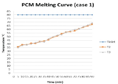
Figure 4. PCM Melting Process Graph (Case 1)
The discharging process has been conducted with same flow rate of 3 litre/minute. The normal temperature of water at 30 0C is circulated through PCM tank. The heat which is stored in the thermal energy storage tank is absorbed by water and the temperature of the water is increased. The temperature of PCM and water is recorded at an interval of time 5 minutes. The discharge process is continuous until the PCM changes its state from liquid to solid and the temperature of output water reduces to atmospheric temperature. The result of this process is plotted in graph shown in Figure 5. The PCM took 45 minutes to reach an atmospheric temperature of 36 0C. T2 and T3 show the temperature of PCM. The graph shows the gradual decrease in the temperature of PCM. It took 45 minute to reach 36 0C temperature. The total energy is stored in PCM is retracted during this process.
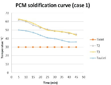
Figure 5. PCM Solidification Process Graph (Case 1)
In this case, the research changes the flow rate of Heat Transfer Fluid and water. The process is same as case 1. The result is shown in Figure 6. It took 100 minute to melt the PCM completely and reach the temperature 67 0C. The graph shows a gradual increase in the temperature of PCM.
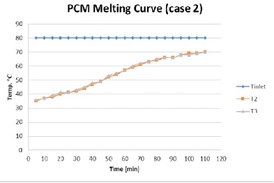
Figure 6. PCM Melting Process Graph (Case 2)
The flow rate is reduced to 1.93 litre/minute. The result is plotted in graph as shown in Figure 7. The temperature of PCM and water is recorded at an interval of time 5 minutes. The graph shows a gradual decrease in the temperature of PCM. PCM took 60 minutes to reach the 35 oC temperature.
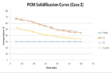
Figure 7. PCM Solidification Process Graph (Case 2)
Figure 8 shows the temperature of water outlet at two different mass flow rates. The graph shows that by reducing the flow rate of water, PCM cools at a slow rate. The efficiency is increased by reducing the flow rate.
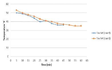
Figure 8. Discharge Water Temperature ( C) vs time (minute)
Based on the experimental work carried out, following conclusion could be drawn.
Paraffin wax is a good PCM for energy storage in latent heat storage system. Paraffin wax has a suitable transition temperature range of 45-55 °C. A simple tube-in-tube heat exchanger system can be used for energy storage with reasonable charging and discharging time. The melting has been more at the top and nearer to the inner tube. The solidification process has been rapid at the point nearer to the inner tube carrying heat transfer fluid. This setup can be used to store thermal energy in solar water heating applications. The operating and running cost of the system is also economical.
I would like to thank and acknowledge Prof. Jayashree Zope, Faculty of Mechanical Engineering, TSSM's Bhivarabai Sawant College of Engineering and Research, Narhe, Maharashtra, India, for their invaluable contribution to this project.