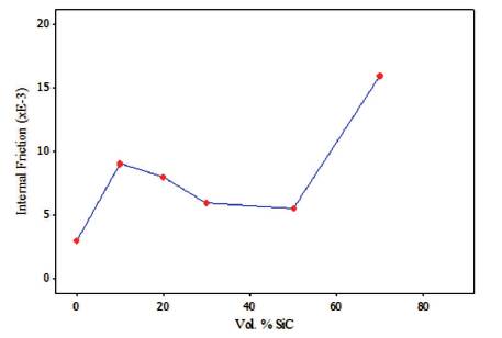
Figure 1. Damping Behavior of SiC/AMMCs as Function of Reinforcement Content (Wycliffe, 1993)
Brake is one of the most important control components of the vehicles. Brake is used in all automotives, locomotives aircraft, and some stationary machines. Different types of brakes like band brakes, drum brakes, electromagnetic brakes are most commonly used. Good and reliable design of brakes has assumed utmost importance in the context of modern world, where the increase in the number of vehicles and improvement in their speed is an everyday phenomenon. Therefore, a brake should be capable of stopping a vehicle within the shortest distance possible, under all conditions of motoring and the brake system should be completely reliable. The design methods used for brakes are based mainly on statistical considerations, and a number of simplifying assumptions. However, in reality, brakes are exposed to operate under extreme environmental conditions and it is the dynamic performance of the brake, which really matters. This paper discusses about the various factors affecting the performance of the Disc Brake system.
Brake system is one of the necessary components of any vehicle. To stop the vehicle within smallest distance possible, braking system is used. For improving the performance of the brake system, the fuel consumption and weight need to be reduced in automobiles. This article discusses the use of MMC material instead of conventional material. MMCs have improved, in the last three decades in a big way, primarily because of their superior mechanical and tribological properties compared to monolithic materials. The principal advantage MMCs enjoy over other materials lies in the improved strength and hardness on a unit weight basis. Extensive application on MMCs to get required properties in particular application needed some parameters: the extensive parameters such as (Varying speed, applied load) and intrinsic parameters such as (particle size, particle volume fraction).
The performance of the brake depends mainly on matrix and reinforcement material. The factors depend on rotor thickness: 29.1 mm, cooling air speed: 3.2 km/h, rotor diameter: 235 mm, vent thickness: 10 mm, ambient temperature: 25o C (Dwivedi, 1995).
The evaluation of heat resistance were performed under some conditions such as braking deceleration of 4.4 m/s2 to get a speed reduction from 100 km/h to 95 km/h. For evaluation of frictional properties at a deceleration of 3.4 m/s2 , temperature of the rotor before braking was 120o C and initial vehicle speed was 65 km/h (Nakanishi, et al., 2002). The test was conducted on cast iron and MMCs brake rotor. The inner and outer diameter and thickness are 180, 140, and 4 mm respectively. The surface roughness value is 1.5 m. The casting of aluminium metal matrix composites rotor was made to size of outer diameter, inner diameter and thickness as 180, 110 and 5 mm respectively. The semi-metallic pin as diameter of 10 mm rod was used for the wear test (Nataraj, et al., 2006) .
The load sensitivity test was carried out and the average friction reading has been taken repetitive of half-minute duration. The initial load of 1269 N was reduced to 669 N in steps of 200 N at constant speed of 6.1 m/s and temperature of 177 and 316o C respectively. The speed sensitivity tests was carried out by same condition of temperatures, load of 669 N and increased speed from 6.1 m/s to 14.9 m/s. Wear tests were carried out by increasing the variables like 177 to 343o C, 669 to 1269 N and 6.1 m/s to 14.9 m/s respectively (Zhang, and Wang, 2007). The temperature and wear was investigated for a specimen A and B at a load of 90 kg and speed of 300 rpm and measured with running speed of 5,10, and 15 minutes over a temperature range of 230-370o C (Mosleh, et al., 2004).
The disc has a diameter of 45 mm and thickness of 10 mm. The alloy as following composition such as Al-8.5, 9.5% Si, 0.45-0.65% Mg, 0.2% Fe (max), 0.2% Cu (max), 0.2% Ti (max), reinforced with SiCp of average diameter of 8 μm. The dry sliding test was carried out at sliding speed of 0.94 m/s and load were increased of 100 to 750 N. Each test was carried out for 30 minutes at ambient temperatures for 10 and 20 volume percentage reinforced SiCp to the aluminium alloy (Yang, et al., 2006). The braking performance of the AMC brake rotor was tested and dynamometer braking tests were carried out for inertial load of 45 kgm2 . The cooling speed of air is 12 m/s and atmospheric temperature is maintained at 18o C (Ding, et al., 2000).
The intrinsic factors are very much important in influencing the property of the brake system. The factors such as reinforcement size, reinforcement volume fraction, and thermal conductivity of the materials are very important.
The change in MSST (Maximum Steady State Temperature) with inertial load for 29.1 mm thick rotor of three different materials such as 360/SiCp (30), 360/SiCp (20) and cast iron materials, produces a same relationship of cast iron and 360/SiCp (30) rotor material (Dwivedi, 1995) . The reinforcement material for cast MMCs rotor has SiCp of 25- weight % and 43 m size (Nataraj, et al., 2006) . SiCp of 10 and 20 vol. % reinforced with aluminium alloy, the particle size of 8 μm was used in the composites (Yang, et al., 2006).
While increasing the reinforcement content, initially the internal friction increases, then decreases slightly of loading 50 vol. % SiC and rapidly increases with increasing the amount of vol. % as shown in Figure 1 (Michael, and Aghajanian, 1995). The volume fraction of hard particles increases from 20-vol. % to 30-vol. %, which produces the good productivity in rotor. It proves the enhanced heat resistance capacity of rotor material (Nakanishi, et al., 2002). The volume fraction of reinforced SiCp are 25 weight % in A356 matrix alloy (Nataraj, et al., 2006) . The friction and wear behaviours of brake material are made of aluminium matrix composites reinforced with 25 vol. % of SiCp material (Zhang, et al., 2007).
Figure 1. Damping Behavior of SiC/AMMCs as Function of Reinforcement Content (Wycliffe, 1993)
The bronze-based break lining was produced with reinforcing a 0.5, 1, 4 and 4 wt. % of Al2O3 material. The friction and wear behaviours of bronze based and Al2O3 powder with plain bronze-based break lining material are compared (Boz, and Kurt, 2007). The composites reinforced with 10% particles show fine sizes of wear debris than 15 and 20% reinforced composites (Triches, et al., 2004). In aluminium metal matrix composites, SiCp of 10 and 20 vol. % of reinforced aluminium alloy for friction and wear tests was carried out for both composition (Yang, et al., 2006).
The thermal conductivity of the rotor material increases between 50-200 W/m-K, and it decreases the Maximum Steady State Temperature (MSST). As a result, when there is more than 100 W/m-K thermal conductivity, the rotor materials produced are more effective. Figure 2 shows that, 200 W/m-K produces the lowest MSST when compared with other thermal conductivity rotor material (Dwivedi, 1995). The specimen material included FC250, for current material is produced and modifying the amount of nickel and cerium inoculation as parameters. The thermal conductivity of the current material is the lowest, and for Ni, is 0.38 and Ce, Tr content material shows maximum thermal conductivity (Uyyuru, et al., 2006) . The surface conditions of the rotors following high speed braking conditions for cast iron and other cast iron materials tests was conducted. A comparison of the surface conditions show that high thermal conductivity cast iron had fewest cracks followed by Ni-Cr-Mo type cast iron, FC250, high silicon type cast iron and Ni-resist type cast iron in that rotor. These results confirmed that the high thermal conductivity cast iron was the most effective material for lowering the heat cracks (Peter, et al., 2003).
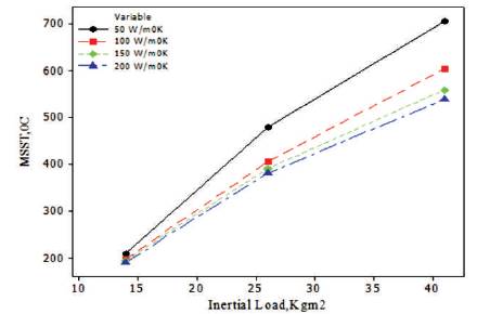
Figure 2. MSST as a Function of Inertial Load for Rotors of Different Thermal Conductivities (Dwivedi, 1995)
The reinforcement size of alumina used in production of rotor was 3.03 μm (Dwivedi, 1995). The hard particle of aluminium metal matrix composites rotor was 20 m and hard particles in the pad was 1-20 m. The cast iron brake rotor (FC) scratches the hard particles in brake pad. The wear powder of the brake pad and scratched out brake material forms a film. Then repeated applications of the brake forms thicken accumulated films.
This accelerates the wear of brake pad and lowers the friction coefficient (Nakanishi, et al., 2002). The size of the reinforcement used in the fabrication of the MMCs was 43 μm of SiCp (Nataraj, et al., 2006). The friction and wear behaviours of same brake material was made by using aluminium matrix material and reinforced with two sizes of SiCp such as 3.5 and 34 m of drum A and drum B respectively. The performance tests of both drums were carried out and concluded that larger size reinforcement material shows good results compared with small size reinforcement as shown in Figures 3, 4, and 5 (Zhang, et al., 2007). The Al2O3 reinforced with bronze-based brake linings was produced and friction and wear test was carried out for plain bronze lining material. For this investigation, bronze based powder was 0.2-80 μm and Al2O3 was 5-120 μm used in fabrication (Boz, et al., 2007). The reinforcement size of SiCp used in composites is 8 μm (Yang, et al., 2006).
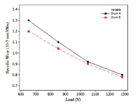
Figure 3. Effect of Load on the Specific Wear Rate of Brake Material at U = 6.1 m/s and T= =177o C (Zhang, et al. 2007)
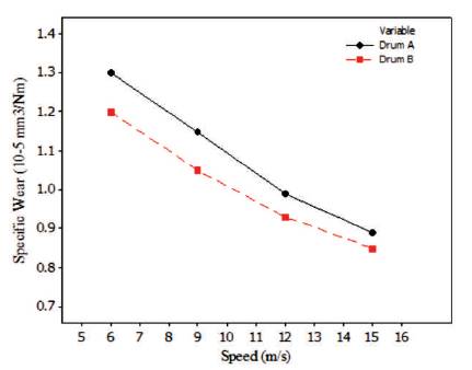
Figure 4. Effect of Speed on the Specific Wear Rate of Brake Material at P = 669 N and T= 1770 C (Zhang, et al. 2007)
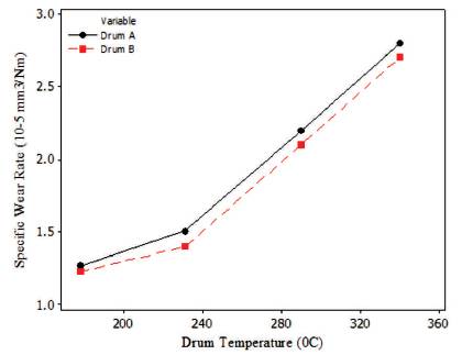
Figure 5. Effect of Temperature on the Specific Wear Rate of Brake Material at U = 6.1 m/s and P = 669 N (Zhang, et al. 2007)
The extrinsic factors are very much important in the performance of the brake system. The extrinsic factors are applied load, sliding velocity, frictional coefficient, frictional force, cooling air speed, and rotor temperature.
The MSST is very much dependent on inertial load, when load is increased for different rotor material, it increases the steady state temperature of the system. Figure 6 shows that MSST is highest for the cast iron as compared with 360/SiCp (20) and 360/SiCp (30) material (Dwivedi, 1995). As applied load increases, the wear also increases. The comparison of aluminium metal matrix composite with cast iron rotor is shown in Figure 7 (Nataraj, et al., 2006).
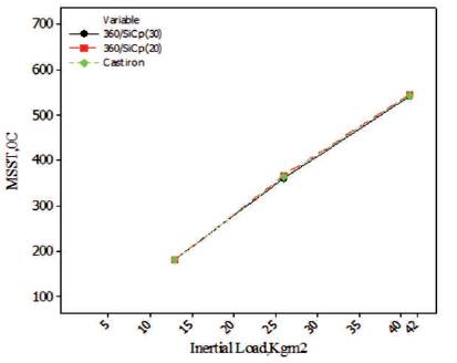
Figure 6. MSST as a Function of Inertial Load for three Different Rotor Materials (Dwivedi, et al., 1995)
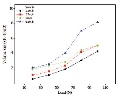
Figure 7. Variation of Wear in MMC with Applied Load for Different Sliding Velocity (Nataraj, et al., 2006)
The friction coefficient decreases with increasing load because the present load was sufficient for large SiCp fracture for plastic deformation of Al-MMCs and subsequently small size SiCp pulls out. The specific wear rate increased with increasing speed which has been obtained for both drum brake materials (Zhang, et al., 2007). The applied load increases, which increases the coefficient friction (Jang, et al., 2004). The high volume of reinforcement or large size reinforcement, wear rate increases as load increases. In other hand, for low volume reinforcement, opposite effect of load on wear has been observed (Uyyurua, and Surappa, 2007). Increasing the loads from 100 to 750 N at ambient temperature tests were carried out for 30 minutes for analyzing friction and wear behaviour of the composites (Yang, et al., 2006) .
The sliding velocity increases with increasing wear loss in the rotor. For maximum sliding velocity, higher wear has been observed for different applied load. For lower load, it produces a low wear rate and while increasing the load up to 100 N produces a maximum wear as observed in Figure 8.
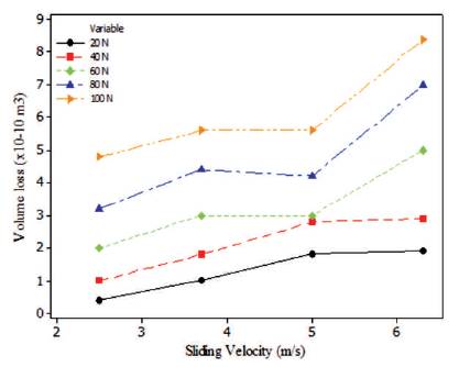
Figure 8. Variation of Wear in MMC with Sliding Velocity at Different Loads (Nataraj, et al., 2006)
The wear losses when compared with AMMCs and cast iron, produces a lower wear. In AMMCs, material contains hard particles of SiC, which acts as load bearing member in composite material (Nataraj, et al., 2006). High temperatures are attained for high speeds and the induced friction coefficient decreases. The specific wear decreases with increasing speed for both drum brake material (Zhang, et al., 2007). The friction material containing Cu fibres decreases the coefficient of friction with increasing the sliding speed, same trend was observed in friction material used as steel fibres. In other hand, the friction material containing Al fibers show small change with sliding speed (Jang, et al., 2004). The inverse proportionality has been observed between the sliding speed and wear rate, i.e. increasing the sliding speed decreases the wear rate (Uyyurua, et al., 2007). The dry sliding tests were carried out for analyzing behaviour of friction and wear of AMMCs at sliding speed of 0.94 m/s (Yang, et al., 2006). The friction coefficient decreases with increasing the rotor speed (Ding, et al., 2000).
When analysing the variation of friction force with applied load, more variations were observed with applied load than with sliding velocity. At higher loads, the frictional force is higher because of more contact area with frictional material surface. In all these cases, the frictional force increases with increase in applied load as shown in Figure 9 (Nataraj, et al., 2006). The friction force was changing depending upon the temperatures 98 and 345o C. A higher variation in friction force was obtained for material containing a 2 and 4% Al2O3 reinforced material (Boz, et al., 2 3 2007). The friction process is accompanied with the formation of metastable phases, which generates consequences of complex contribution of temperature and pressure (Filip, et al., 2002).
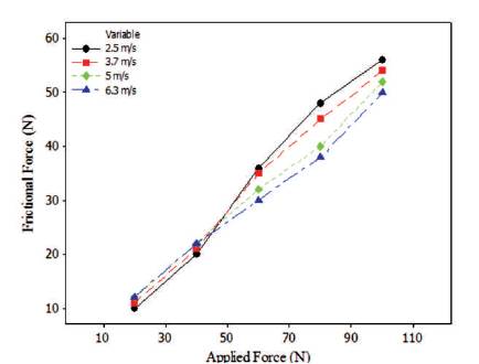
Figure 9. Variation of Frictional Force with Applied Force at Different Sliding Speed (Nataraj, et al., 2006)
The MSST variation of inertial load for three different cooling air speed for 29.1 mm thick rotor of A356/SiCp (30) is shown in Figure 10. It clearly says that cooling air speed is increased from 3.2 km/h to 12.8 km/h, it drastically drop in MSST as shown in Figure 10 (Dwivedi, 1995).
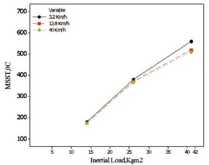
Figure 10. MSST as a Function of Inertial Load for Rotors subjected to Varying Cooling Air Speed (Dwivedi, 1995)
The MSST variation of constant inertial load for different rotor thickness clearly says that increasing the rotor thickness decreases the MSST (Dwivedi, 1995).
The production of cast metal matrix composite rotors are done using infiltration process. The infiltration process is quite simple, cost saving, high volume and has many advantages over sand casting process. The sand-casting process can produce the cast iron rotors (Dwivedi, 1995). The liquid metallurgy route (stir casting) produced the MMC (Nataraj, et al., 2006). The bronze based Al2O3 reinforced material was produced by powder metallurgy route (Boz, et al., 2007). The Al-Si/SiCp composite material was fabricated by using stir-casting method, for studying the tribological behaviour of the composite material (Uyyurua, et al., 2007).
The performance tests were conducted for conventional aluminium metal matrix rotor material, its rotor temperature reached to 490o C. The evaluation of cast iron rotor on same conditions, attained the temperature of 410o C (Nakanishi, et al., 2002). The friction fade has observed at high temperatures, and it can recover quickly of cooling of brake drum. The specific wear was increased with increasing drum temperatures for both drum brake material A & B (Zhang, et al., 2007). The coefficient of friction changes with sliding temperature, in which adhesion and deformation resistance of the material change as a function of temperature (Jang, et al., 2004). The two specimens of A and B are semimets and organic friction materials. The thermal conductivity of semimets has much higher the temperature profiles across the interface and is different. The disc temperature rises will take place due to frictional work; it suggests that thermal energy distribution varied from couple to couple.
The magnitude did not correlate with debris pattern, composition or shape of extracted debris particles (Yamabe, et al., 2002). The maximum rotor temperatures reached during the tests were around 390 to 425o C (Hoyer, et al., 1999). The temperature rises to 535o C before failure temperature and after exceeding this temperature it will reach to 556o C where failures occur (Triches, et al., 2004). The overheating of the friction coefficient was observed during critical loading conditions. The influence of temperature on friction coefficient, increase in contact temperature of 110o C produced a decrease in friction coefficient (Yang, et al., 2006). The friction coefficient change with increasing number of fade stops. The friction coefficient decreases when the temperature is higher than 350o C (Ding, et al., 2000).
The variation of frictional coefficient with frequency of braking at particle diameter ratio of 10 did not lower the friction coefficient and kept constant range of 0.39-0.4 as shown in Figure 11.
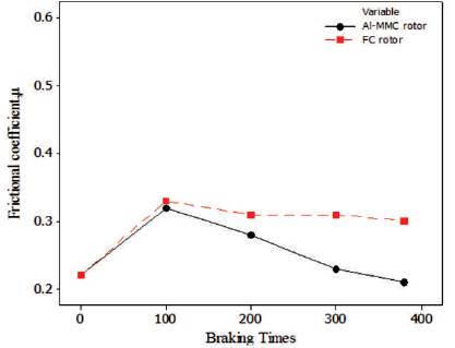
Figure 11. Variation of Friction Coefficient with Braking Times (Nakanishi, et al., 2002)
The friction coefficient of AMMCs was lower than FC rotor material at initial speed of 100 km/h as observed in Figure 12 (Nakanishi, et al., 2002).
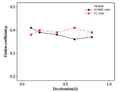
Figure 12. Variation of Friction Coefficient with Deceleration (Nakanishi, et al., 2002)
The frictional coefficient of MMC was 1.25 times more than cast iron while sliding under same conditions, which will enhance the braking performance. The friction coefficient decreases with increasing speed and load is observed in Figures 13 and 14 respectively (Nataraj, et al., 2006) .
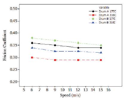
Figure 13. Variation of Speed with Friction Coefficient at P=669 N and T=177o C (Zhang, et al. 2007)
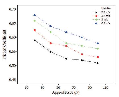
Figure 14. Variation of Friction Coefficient with Applied Load for Different Sliding Speed (Nataraj, et al., 2006)
The AMMCs material having high thermal conductivity, due to this conduction, convection and thermal radiation easily dissipate heat through the rotor surface which reduces the friction coefficient. On other hand, due to tribofilm formed due to large and high volume SiCp reinforced in aluminium material, reduces the friction coefficient. The friction coefficient was converged at two temperatures 177 and 316o C (Zhang, et al., 2007). The coefficient of friction of AMMCs disk shows less response for sliding speed compared with gray iron disk. With applied pressure, it is found that the friction material with Al fibers show high value of coefficient of friction (Jang, et al., 2004). The observed friction coefficient was constant around 0.30. The friction coefficient decreases with increasing normal load. The friction coefficient decreases with increasing sliding speed (Uyyurua, et al., 2007).
The coefficient of friction varies with pressure significantly less than in contacts with grey cast iron discs. The variation of coefficient of friction between 0.4 and 0.6 for different conditions, is about two times higher friction compared to contacts with grey cast iron discs (Kermc, et al., 2005). The friction coefficient decreases when increasing testing temperatures (Filip, et al., 2002). The friction coefficient existing for cast iron rotor is 0.38 and for ceramic composite, the friction coefficient is obtained about 0.21 (Yamabe, et al., 2002). The friction value varies for different friction material. For all three base matrices, the friction is highest for Sb2S3 , around 0.47-0.49 and little lower for PbS, around 0.40-0.47. Highest variations are observed for Cu2S,around 0.37-0.53 (Yoshio jimbo, et al., 1990).
The coefficient of friction values are maintained up to elevated temperatures when grey iron disk contain higher graphite contents. The coefficient of friction rapidly decreases at lower temperatures, from this change of coefficient of friction as a function of temperature (Hoyer, et al., 1999). The coefficient of friction is near 0.4 in early stages but it will drop sharply when temperature is raised above 220o C. The temperature in range of 25-450o C gives stable friction coefficient. The wear in friction material is highest in no reinforcement material, it decreases with higher volume fraction with coarse particles (Triches, et al., 2004). The friction coefficient increases with load for SiC20 and is almost independent on load for SiC10. In region 1, the SiC10 is contributing in abrasion action for this friction coefficient is independent with load. SiC20 is contributing to an adhesive action, because material which contains higher hardness reduces the abrasion action. In region 2, the coefficient of friction for SiC10 is lower than 0.3. In region 1, friction coefficient is quite high around 0.45 for SiC10 and SiC20 particulate reinforced material (Yang, et al., 2006). The friction coefficient decreases with increasing the pressure from 2 Mpa to 10 Mpa (Ding, et al., 2000) . The increasing in SiCp reinforcement content in composition initially increases the internal friction then gradually decreases slightly to loading of 50 volume %. The friction increases rapidly when load increases further (Michael, et al.,1995).
The particles ranges from 2 to 20 (rotor/pad) for both brake rotor and pad produces the sufficient wear properties (Nakanishi, et al., 2002). The wear is low at lower value of applied load. When the applied load increases, the wear loss also increases.
The comparisons of wear of cast iron rotor to the MMC rotor slides against friction material which results in reducing the wear about 1.5 times of MMC rotor material compared with cast iron material (Liu, and Rhee, 1978, and Cho, et al., 2003). The more wear was observed for without Al2O3 reinforced material. The wear resistance of the specimen increased with increasing the amount of ZrSiO4 (Boz, et al., 2007). When the normal load increases the wear particles become bigger, this term also explains compacting pressure on agglomerates (Liu et al. 1978).
The wear increases with increasing disc temperature (Filip, et al., 2002). Performance tests for different friction materials on dynamometer tests were conducted. The friction materials used in this test are Cu2S, PbS, Sb2S3 . The results show that little variation of wear was observed around 0.1-0.3 mm (Yoshio Jimbo, et al., 1990). The wear rate concerned in region 1 is lower for SiC10 because it contains a lower hardness material. The wear rate increases with applied load for SiC10. The wear rate is absent because it forms the transfer layer which protects the material (Yang, et al., 2006). The SiC reinforced aluminium alloy gives lower wear rate than cast iron. The presence of SiC particle in composites, forms the layer and prevents the AMC from sever, wear (Ding, et al., 2000) . The wear resistance of the composites decreases with decreasing content of 30% volume of SiCp. Further drop in wear resistance exists in further decrees in 20 volume % of SiCp content in composites, but performance of the material was twice that of heat treated aluminium (Wycliffe, 1993, and Howell, and Ball, 1995).
The tests were repeated 2000 times, under initial vehicle speed of 10-30 km/h, brake fluid pressure of 0.2-4 Mpa and initial- braking pad, temperature of 40-200o C. The maximum sound volume was 78 dB. This brake squeal is equivalent to the conventional FC brake pad (Nakanishi, et al., 2002). The brake squeal strongly depends on pressures and temperatures acting between disc rotors to the friction material. Efficient solution to reduce the squeal noise is by adding the damping material to the brake system up to 20 db (Cho, et al., 2003). The parameters of metal matrix composite material for disc brake system are as shown in Table 1.
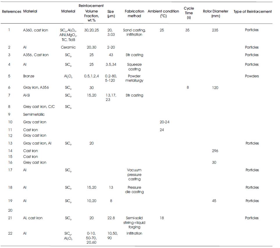
Table 1. Different Parameters of Metal Matrix Composite Material for Disc Brake System
The following conclusions were drawn from the discussion.
The intrinsic and extrinsic factors have more influence on the performance of the brake system. The intrinsic factors are reinforcement size, reinforcement volume fraction, and thermal conductivity of the materials. The extrinsic factors are applied load, sliding velocity, frictional coefficient, frictional force, cooling air speed, and rotor temperature. Alumina reinforced rotors offer better performance in maximum operating temperature when compared with silicon carbide reinforced rotors. The performance of the brake depends mainly on matrix and reinforcement material. These results confirmed that the high thermal conductivity cast iron was the most effective material for lowering the heat cracks. The volume fraction of hard particles increases from 20-vol. % to 30-vol. %, which produces the good productivity in rotor. It proves the enhancement of heat resistance capacity of rotor material. Since MMC material has more wear resistance and stable friction coefficient as it contains a hard SiC particles in aluminium matrix material, it is a better material for brake drum applications. The friction coefficient and wear property strongly depends on the size of reinforcement SiCp . Al-MMCs containing a small size of SiCp is not suitable for manufacturing of brake rotor drums. The large size SiCp reinforcement in the matrix has high wide size distribution, wear and friction coefficients when compared with small size reinforcement. The friction and wear behaviour of Al-MMCs (SiC10 and SiC20, containing 10 and 20 vol. % of reinforcement) strongly depends on applied load and external heating. Many of the combination of properties are offered by high reinforcement content particulate MMCs which are attractive for automobile applications such as brake components, and engine components.