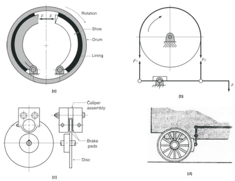
Figure 1. Different Types of Brakes (a) Drum Brake, (b) Band Brake, (c) Disc Brake, (d) Block Brake
Brake system is one of the necessary components of the vehicle. The braking system is used to stop the vehicle within a smallest distance possible. A Review will be helpful in understanding the improvement of the performance of the brake system, to reduce the fuel consumption and weight in automobiles. This article discusses the use of MMC material instead of conventional material. An improvement in MMCs is observed during the last three decades in a big way, primarily because of their superior mechanical and tribological properties compared to monolithic materials. The principal advantage of MMCs over other materials lies in the improved strength and hardness on weight basis. The discussion is concentrated on selection of matrix and reinforcement material and variables considered during the performance test on disc brake system.
Brakes can be comprehensively defined as devices used to dissipate kinetic energy by slowing down or stopping a moving element. A brake is used in all automotives, locomotives, aircraft and some stationary machines. Different types of brakes like band brakes, drum brakes, electromagnetic brakes are most commonly used. A good and reliable design of brakes has assumed utmost importance in the context of modern world, where the increase in the number of vehicles and improvement in their speed is an everyday phenomenon. Therefore, a brake should be capable of stopping a vehicle within the shortest distance possible, under all conditions of motoring and the brake system should be completely reliable (Mikael Eriksson et al., 2002). The design methods for brakes are based mainly on statistical considerations and a number of simplifying assumptions. However, in reality, brakes are exposed to operate under extreme environmental conditions and it is the dynamic performance of the brake, which really matters (Mohsen Mosleh et al., 2004) and (Osterle et al., 2007).
The performance of the brake is investigated by the effects of material properties and, the geometry on pressure and temperature of sliding bodies have become very important due to increasing demands on brake performance (Daniel, 2004). The tests were conducted on a wide variety of aluminum-boron-carbide (Al-B-C) microstructures attainable by process design variations. Al- B-C cermets have more orders of magnitude and more wear resistance than current materials. Al-B-C cermet shows no evidence of fading with increasing temperature (Chapman et al., 1999). The variation in friction and wear between different pad materials is much larger, when braking is performed at high temperature and pressure than at low temperature and pressure, where furthermore, there is no significant effect on the metal sulphides. This correlates with the surface analysis, which indicates that no friction film is formed on the disc at low duty (Singh et al., 2010 ). Characteristics and current difficulties encountered in tackling brake squeal are described. The analytical, experimental and numerical methods used for investigation of brake squeal are also discussed (Hoyer et al., 1999 ). The two identical brake drums were made of aluminum matrix composites reinforced with two sizes of SiCp which were tested under the same operating conditions. The friction performance depends on the size of SiCp (Joseph et al., 2002). The frictional properties of gray iron with different microstructures were investigated. The amount of free ferrite (and pearlite) on the gray iron disk did not affect the coefficient of friction (COF) (Shaoyang Zhang & Wang, 2007 ).
The pin-on-disc wear tests were carried out with Compact Graphite Iron (CGI) and three different gray irons, for given applied pressures; wear of CGI is higher than that of gray irons. CGI, showed greater friction force and temperature than gray iron (Cho et al., 2003). The economics of machining of hot forged Al MMC brake discs are economical compared to grey cast iron (Varuzan et al., 2002 ). The friction tests were carried out on gray cast iron and role of Al2O3 on brake lining friction materials. The highest friction coefficient was obtained in the samples containing Al2O3 in the range of 4% due to an increase in the temperature during friction. The addition of Al2O3 in 2% to the sample shows stable friction coefficient. The highest wear was obtained in the sample containing no Al2O3 . Wear resistance of the samples increased with increasing the amount of ZrSiO4 (Mustafa Boz & Kurt, 2007).
The classification of the brakes is shown in Figure 1.
Figure 1. Different Types of Brakes (a) Drum Brake, (b) Band Brake, (c) Disc Brake, (d) Block Brake
Among these, block brakes and band brakes are used in stationary machines. Automobile vehicles use disc and drum brakes. They are very compact and can be fitted easily within the rim of a vehicle is wheel. Each kind of brake has its own advantages and disadvantages (Cueva et al., 2003 ).
The following are the advantages and disadvantages of disc brakes over drum brakes.
Due to the above mentioned disadvantages over drum brakes, disc brakes are widely used in aircrafts, automotives, industrial and mining equipments nowadays. The selection of brakes is based on the performance, environmental conditions and applications is listed in Table 1.
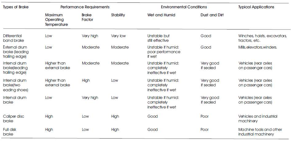
Table 1. Selection of Right Brakes
A brake system consists of the following parts:
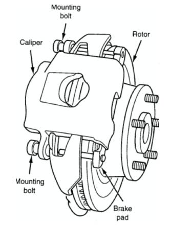
Figure 2. Disc Brake Assembly
Friction materials (pads) are mounted to the caliper assembly. The various parts of a brake are shown in Figure 2. The following are the three basic designs for the disc brake.
1. Rotor
2. Caliper
3. Brake pad
The caliper is fixed and the friction pad is on only one side of the slide over the shaft in the axial direction, and comes in contact with the fixed friction pad to give the necessary torque reaction.
The caliper is a device for loading the friction pad against the transmitting torque reaction to the stub axle. The caliper should be designed for maximum stiffness and less weight as possible. According to the new combination and Spur, the caliper should not deflect more than 0.025 mm per 7 kg/cm pipeline pressure, otherwise the brake will drag because deflection has the same effect on the adjuster as lining wear. The caliper can be a single U-shaped bridge piece straddling a two bridge piece construction. The two bridge caliper is stiffer because of smaller bending moment.
In this case, the disc is fixed to the shaft and the friction pad is fixed to a caliper. The caliper moves in a slot and the friction pad comes in contact with the rotating disc to give the required torque reaction. The friction pad is only on one side of the disc (Jang et al., 2004).
Friction pads can be circular, segmental, rectangular, square or slightly oval. The pads of these shapes can show different wear rates at outer, inner, leading and trailing edges. Eventually, the pad then wears more or less evenly in an axial direction and a uniform rate of working occurs over the pad. The circular pads cause greater wear at the center of rubbing pad and the area of circular pad is smaller than the other shapes for the same outer and inner radius of the rubbing surface. The pads normally occupy about 1/10th to 1/9th of the swept area of the disc. In general, there is no optimum pad site. In most designs, the friction pad is attached to a metal back-plate, which takes the torque reaction on the caliper housing during braking, by molding the pad into the back plate. The back plates are often segmental and engages in corresponding abutments in the caliper (Thomas & Mackin, 2002).
Brakes pads are generally made of thermosetting resins reinforced by asbestos fibers. Small amount of other ingredients are also added to impart the required friction and wear properties. Another type of lining is used which contains a roll of resin based friction materials and the values of co-efficient of friction of these materials at different operating temperatures are also obtained. It has been found that, the brake friction is strongly controlled by the lubricating action of resin, where there is no correlation between the brake friction behavior and the mechanical properties of the resin based composites. The coefficient of friction drops slowly at low temperature and drastically increases temperatures. This happens because at high temperatures, the polymer tends to get deoxidized. Minute fragment of materials are plucked out of the lining surface at the real contact areas and this constitutes wear. A rough disc also wears away the lining by micro machining effect (Yang et al., 2006).
When the hydraulic pressure is applied to the caliper piston, it forces the inside pad to contact the disc. As pressure increases, the caliper moves to the right and causes the outside pad to contact the disc. Braking force is generated by friction between the pads as they are squeezed against the rotor. Since brakes do not use friction between the lining and rotors to increase braking power as drum brakes do, they are less likely to cause a pull. The friction surface is constantly exposed to the air, ensuring good heat dissipation, minimizing brake fade. It also allows for selfcleaning as dust and water are thrown off, reducing friction differences (Peter. J, Balu & Harry, 2003).
Unlike drum brakes, disc brakes have limited self- energizing action, making it necessary to apply greater hydraulic pressure to obtain sufficient braking force. This is accomplished by increasing the size of caliper piston. The simple design facilitates easy maintenance and pad replacement. Normally, the Brake discs are made from Gray Cast Iron of grade GG 250 because of its resistance to scoring and thermal cracking. The solid and ventilated types of discs are shown in Figure 3 (Hiroaki Nakanishi et al., 2002).
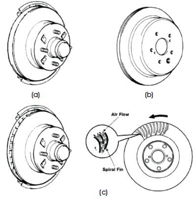
Figure 3. Types of Disc Brake Rotors (a) Solid Type, (b) Solid Type with Drum, and (c) Ventilated Type
( Boniardi et al., 2006 & Yoshio et al., 2000) conducted various experiments on solid and ventilated discs and found that the rise in lining temperature is much lower than that for a solid disc for the same braking conditions. Since, the heat dissipation capacity of a ventilated disc is much higher than the solid disc; it is used most widely in modern disc brakes. The ventilated internal radial fins that move air over many exposed surfaces to dissipate heat, separates the braking surface.
During braking, the vehicle is retarded by other forces besides the braking force. Drag force caused by wind resistance can be significant at high speeds and is a function of vehicle speed as well as the cross sectional area of the vehicle. If the clutch is not disengaged during breaking, the engine develops a retarding force approximately proportional to engine speed, which will depend on the rod speed and the gear, engaged. In addition, the rolling resistance, friction in the wheel bearings, differential, etc. help to slow down the vehicle. However, for the design considerations, these factors have not been taken into account as their relative contribution to total braking effect is quite small and is of the order of 0.04g (Paul, 2007).
Although maximum deceleration of a car may exceed 1g, applications involving decelerations more than 0.5g are rare. In an emergency, driver may require the maximum possible deceleration. The force that can be exerted at the road - tyre interface, is limited by the adhesion between the road and the tyre. If a braking torque is applied which produces a force greater than this value, the brake will lock the wheel and the tyre slips or skids. Therefore, a vehicle should be able to utilize all available adhesion between tyre and road, whilst at the same time permit the driver to maintain direction control of the vehicle (Natarajan et al., 2006 ).
The size of the area of real contact between the pad and the disc, and the composition of the outermost surface layers within this area, is far from constant but will vary due to changing pressure, changing temperature, deformation and wear. The contact pressure may vary on different time scales both locally and globally, due to different processes (Junichiro Yamabe et al., 2002).
Naturally, a change in the braking force will result in a corresponding change of the elastic compression of the pad. The actuation and variation of the braking force can be quick due to manual “fine tuning” during braking or due to ABS (Anti-lock Braking System) brake power variations. The associated pressure changes are global over the brake pad (the average compression of the pad varies) and on a time scale of 1/1 s. Ideally, the resulting braking power should be proportional to the pedal force. A quick brake pressure increases momentarily, thus results in a corresponding elastic compression of the pad. This compression will result in more contact plateaus becoming engaged, as shown in Figure 4 (a), and an increased load on the already engaged contact plateaus will result in a higher area fraction of real contact within these plateaus as shown in Figure 4 (b).
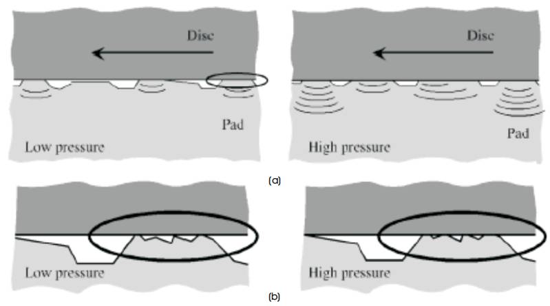
Figure 4. Illustration of the Mechanisms for Rapid Contact Area Variation: (a) The Elastic Loading and Unloading of Contact Plateaus, i.e. the number of engaged contact plateaus increases due to the Elastic Deformation of the pad; (b) The Area Fraction of Real Contact within Individual Plateaus increases due to Local Deformation
Because of the pad compression, the pressure may vary locally over the pad surface. Vibrations cause rapid local pressure variations in the brake system, such as brake squeal. Brake squeal vibrations are associated with bending and wave motions of the pad and disc. These deformations result in local pressure variations over the contact surfaces, often on a time scale of milliseconds or less. The mechanisms for contact area variations are the same as in the global processes.
In addition to the rapid mechanisms of contact area variation, a number of slow mechanisms are operating. These become important in determining the nature and size of the contact area if sufficient time (or sliding distance) is allowed. The slow processes are due to different kinds of wear and accumulation of debris, and to temperature variations. They typically appear on time scales of seconds or more, such as during long, low decelerating brakings or as the accumulated result of numerous brakings. Slow processes appear both on a micro scale, that is on the scale of individual contact plateaus or smaller, and on a macro scale, that is on a scale involving numerous plateaus. The slow processes include:
The growth and disintegration of contact plateaus involve agglomeration and compaction of pad wear debris around a wear resistant nucleus, as discussed in the previous section which is illustrated in Figure 5.
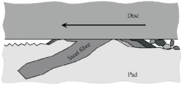
Figure 5. Schematic Drawing of the Mechanism Proposed for Slow Contact Area Growth due to Accumulation and Compaction of Debris
When the load on a contact plateau is increased, the small areas of real contact within the plateau will flatten plastically and by wear. These processes result in an increased area of real contact against the disc. When the load is decreased, the wear and deformation of the points in real contact will tend to reduce their contact with the disc.
The disc is continually worn, chiefly by the harder components in the pads. This wear will initially polish the disc surface, to make it better adapted to the pad. The individual contact plateaus on the pad will correspondingly experience milder contact conditions along the less rough sliding path. Due to the inhomogeneous structure of the materials, the continuous wear on both the disc and the pad will not be evenly distributed. However, the mutual adaptation to the shape of the counter surface will result in wavy surface. On the disc, the waves will form concentrical circles. In a steady state situation, the matching between the two parts is perfect, and each individual contact plateau will experience a smooth ride. However, small misalignments or movements between brakings or other changes will result in mismatched surfaces and a reduced area of real contact.
During moments of high and increasing temperature, the pad surface will be hotter than the interior and the back plate. This will result in convex bending of the pad and hence an uneven pressure distribution occurs as shown in Figure 6. The pressure reduction on the leading and trailing edges will result in a corresponding uneven distribution of wear; i.e. the pad will become thinner in the centre. When returning to a lower temperature, the pad will straighten out. Now, the uneven wear during the bent situation will result in reversal of the uneven pressure distribution. A similar behaviour may also be present for the mating part of the friction couple, the disc. Due to thermal instability, the disc may buckle along the sliding direction causing areas with locally high temperatures, known as hot spots.
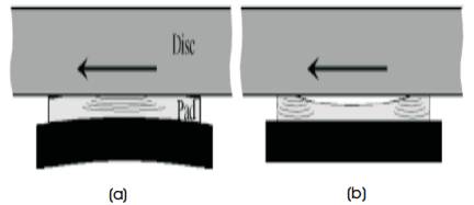
Figure 6. Mechanism for uneven pressure distribution and uneven wear due to thermally induced distortion of the pad and plate: (a) a hot surface will give the pad a convex bend; (b) when returning to lower temperatures the pad will straighten, but wear during the bent situation will result in an uneven shape and a corresponding uneven pressure distribution
The properties of any surface depend on the prevailing temperature. When the disc and pad are heated during braking, the chemical reactivity on their surfaces, the mechanical properties (thermal softening, etc.), the structure of the pad (decomposition of polymer constituents, etc.), the tendencies for smearing and sticking of wear debris on both surfaces, etc., would be affected. Both the composition and the tribological properties of the surfaces are affected (Ratnesh Dwivedi, 1992 ).
Unloaded contact plateaus are exposed to different “contamination” processes, including oxidation, smearing out of wear debris and road dust, etc., which will change their composition. When the sliding contact is continued, the plateaus will be subjected to a “cleaning” process involving the removal of the less wear resistant surface layers. This cleaning results in an increased degree of metallic contact. The corresponding processes occur on the disc surface. The slow contact surface variation processes are responsible for the slow increase of μ during long brakings; the μ hysteresis reported for brakings under varying pressures; the μ increases during running in of a new disc or a new pad (Junichiro Yamabe et al., 2002).
The conventional disc brake, for example as used in the vehicle industry, consists of essentially three elements in combination: a rotor, at least two opposed brake pads usually supported by a metal backing, and a hydraulic cylinder system carried in a caliper, which press the opposed brake pads inwardly onto the surface of the rotor. The drum brake also contains essentially the same three parts, by means of which the brake pads are pressed outwardly to engage the inner face of the drum. For both types, the hydraulic system is constructed to urge the brake pads into frictional engagement of the brake pads, for example, to slow a vehicle, it generates significant amounts of heat which has several consequences. One of these is that when the brake pads become heated, the brake pads, hydraulic fluid, and the sundry elastomeric materials used in the hydraulic system are exposed to elevated temperatures while the brake is in use. These difficulties have been largely solved; brake hydraulic systems and pad materials resistant to temperatures in excess of 500o C are available.
The rotor or drum has to dissipate the major proportion of the heat generated in braking, and at least the surfaces in frictional engagement with the pads can reach temperatures approaching 500o C. The rotor or drum also has to accommodate the braking forces and desirably should have sufficient wear resistance to have an extended working life. In addition, it has to be made from a material, which can be machined accurately, particularly if the hub is formed integrally with the rotor. The commonest material currently used for disc brake rotor and brake drums is gray iron: it can be readily cast and machined, will withstand both the temperature and stress conditions which occur on braking, and provides an acceptable working life.
However, the use of gray iron as the material for the rotor or drum, does have three significant disadvantages.
The friction material for brakes is shown in Table 2 (Jason & Nepean., 2003 ).
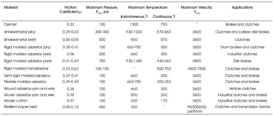
Table 2. Characteristics of Friction Materials for Brakes
In order to overcome these disadvantages, it has been proposed to fabricate brake rotors from light metals, including aluminium and aluminium alloys. Although light metals have acceptable strength properties, and far higher thermal conductivity than iron, the light metals cannot be used alone.
First, the light metals have inadequate resistance to frictional abrasion, and thus cannot provide an adequate working life. To overcome this disadvantage, light metal composite materials have been proposed, which compromise a light metal matrix reinforced with a second material dispersed in the metal matrix. Typical reinforcing materials include silicon carbide, silicon oxide (silica), boron carbide, boron nitride, titanium diboride, titanium carbide and alumina. The elastic moduli of light metal matrix composites (such as an aluminium matrix reinforced with silicon carbide) are higher than the elastic modulus of cast iron and of unreinforced aluminium. In addition, the coefficients of thermal expansion of light metal matrix composites are lower than both cast iron and unreinforced aluminium. These composite materials do have superior wear resistance compared to gray iron components.
Second, even though light metal composites have far better thermal conductivity, adequate strength and wear resistant properties are only obtained if the brake rotor surface in service does not exceed a temperature of above about 400o C. If the rotor surface temperature exceeds this value, and for example rises to above about 500o C, the rotor will fail rapidly due to softening of the light metal matrix. Even commercially available aluminium composites reinforced with silicon carbide (such as duralcan trade mark composites), have a compressive strength as low as about 50 MPa at about 450o C. This is no better than the unreinforced aluminium alloys at that temperature. As a result, commercial light metal composite brake rotors are suitable for use only for relatively light vehicles under about 1100 Kg in weight and even then primarily for the less stressed rear brake rotors.
Primary processes for manufacturing of Aluminium Matrix Composites (AMC) at industrial scale can be classified into two main groups.
The Powder Metallurgy (PM) process involves steps including powders sieving, blending, pressing, degassing and consolidation. The PM methods have been successfully applied to a large number of metal/ceramic combinations. In terms of microstructural requirement, the PM approach is superior in view of the rapid powder solidification. This allows the development of novel matrix materials outside the compositional limits dictated by the equilibrium thermodynamics in the conventional solidification processes. The main deficiencies of this process are complex processing, relatively high cost and hard controlling. As a variant of PM, Powder Injection Molding (PIM) is a near net-shape manufacturing technology that combines the shaping effect of plastic injection molding, with the potential of powder metallurgy for working over metal and ceramic powders.
Liquid phase processes refer to that reinforcements which are incorporated into a molten metallic matrix using various fabrication techniques, including liquid metaldiscontinuous reinforcements mixing, melt infiltration and melt oxidation processes. In this process, a strong bond between the matrix and the reinforcement is formed owing to high processing temperatures. This process has reached an advanced stage of development, while some difficulties exist, including agglomeration of the ceramic particulates during agitation, settling of particulates, segregation of secondary phases in the metallic matrix, extensive, interfacial reactions and particulate fracture during mechanical agitation. High damping MMCs have been made by this method. This approach has been commercialized. Some of the drawbacks of this process include reinforcement damage, coarse grain size and undesirable interfacial reactions. Various high damping MMCs have been made by this method.
This involves incorporation of ceramic particulate into liquid aluminium melt and allowing the mixture to solidify. Here, the crucial thing is to create good wetting between the particulate reinforcement and the liquid aluminium alloy melt. The simplest and most commercially used technique which is known as vortex technique or stir-casting technique is shown in Figure 7. This process is not suitable for the incorporation of sub-micron size ceramic particles or whiskers.
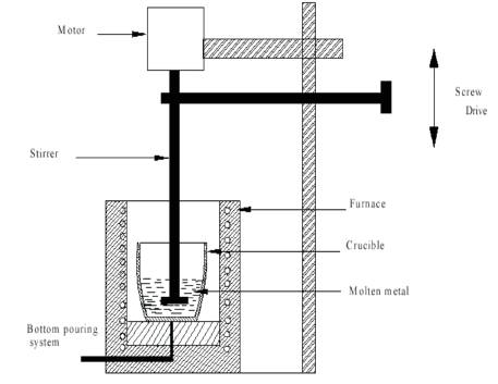
Figure 7. MMC by Casting Riute through Stir Casting Method
Aluminium Matrix Composites (AMCs) having reinforcement volume fraction ranging from 10 to 70% can be produced using a variety of infiltration techniques. Some level of porosity and local variations in the volume fractions of the reinforcement are often noticed in the AMCs processed by infiltration technique. The process is widely used to produce aluminium matrix composites having particle/whisker/short fibre/continuous fibre as reinforcement.
The spray process has been extensively explored for the production of AMCs by injecting ceramic particle/whisker /short fibre into the spray. AMCs produced in this, often exhibit inhomogeneous distribution of ceramic particles.
Porosity is typically about 5–10%. Spray process also permits the production of continuous fibre reinforced aluminium matrix composites. The experimental setup is shown in Figure 8.
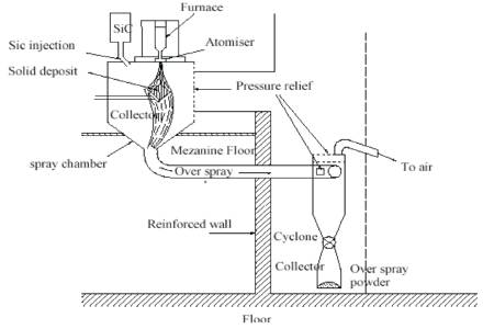
Figure 8. Schematic Diagram of Spray Deposition Method
Several different processes would fall under this category including liquid-gas, liquid-solid, liquid-liquid and mixed salt reactions. In these processes, refractory reinforcement are created in the aluminium alloy matrix. In this process, the alloy of Al-Mg is placed on the top of ceramic preform in a crucible. The entire assembly is heated to a suitable temperature in the atmosphere of free flowing nitrogen bearing gas mixture. Al-Mg alloy soon after melting, infiltrates into the preform and forms composites. This process is flexible and permits formation of both hard and soft phases of various sizes and morphologies that includes whiskers, particles and platelets in aluminium alloy matrices. A major limitation of in-situ technique is related to the thermodynamic restrictions on the composition and nature of the reinforcement phase, that can form in a given system, and the kinetic restrictions on the shape, size and volume fraction of the reinforcement can be achieved through chemical reactions under a given set of test condition (Naresh Prasad, 2009).
Material properties are one of the most important parameters that influence the braking system. The material properties that influence braking conditions are the reinforcement size, the reinforcement volume fraction, and the type of reinforcement material. In most of the MMCs, hard ceramic particles are used as the reinforcements. It reduces the wear and frictional coefficient. Reinforcement materials usually used are SiCp and Al2O3 because it exhibits Maximum Operating Temperature (MOT), improved wear resistance and mechanical properties. As the size of the reinforcement and volume fraction increases, the surface roughness values increase along with friction coefficient and rotor and pad wear for the same braking conditions. The coefficient of friction and rotor wear depends on the nature and percentage of ceramic particles within the composites. The addition of small amounts of graphite causes the friction force and wear to reduce drastically, but with considerable surface finish. The small size reinforcement material supports only the tribofilm, but does not protect the brake material. This small size reinforcement are easily detached from Al matrix due to plastic deformation of matrix material under the influence of load, sliding speed and contact temperature. In large reinforcement material, which forms the thick tribofilm on rubbing surface reduces the specific wear and friction coefficient. The friction and wear performance depends on the size of the SiCp . The small size SiCp is not suitable for brake rotor and drum (Prasanna Kumar et al., 2006). The particle diameter ratio ranges from 2 to 20 (rotor/pad) in order to get sufficient wear properties of both rotor and brake pad. The particle content in the rotor material enhances the heat resistance, in this test optimum content of particle volume is 30%, which gives a good productivity (David, 2000).
The high reinforced content of fabricated aluminium metal matrix composites results in improved physical and mechanical properties. The composite provides significant weight savings over ferrous materials, while possessing the requisite properties for stiffness, critical fatigue, critical wear and critical applications. The composition of Aluminium alloy is shown in Table 3, and properties of the AMCs and cast iron are shown in Table 4 (Aqida et al., 2003).
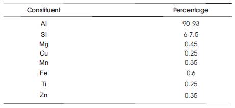
Table 3. Composition of Pure Aluminium Alloy
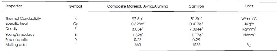
Table 4. Material Properties
Brake components and systems are critical to ensure the safety of high-speed trains. With increasing speed, it is important to reduce the axle weight, especially the unsprung weight. Disk brakes that are an indispensable part for high-speed trains are installed on the axles and belong to the unsprung weight. Lightweight disk brake applied to high-speed trains can reduce the unsprung weight effectively, which is of great significance to the development of high-speed trains. SiC particle reinforced aluminium matrix composites (SiCp /Al) possess many advantages such as high specific strength and stiffness, low density, good thermal conductivity and wear resistance, which makes it a new potential material to produce disk brakes for high speed trains (Yang et al.,2006). Figure 9 shows the microstructures of the gray iron and Al- MMC disks. Physical properties of the two disks are given in Table 5 (Jang, et al., 2004).
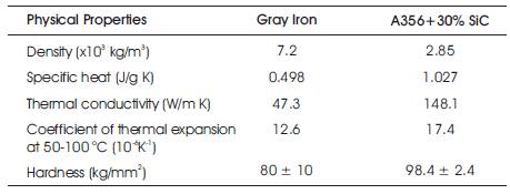
Table 5. Physical Properties of Gray iron and Al-MMC
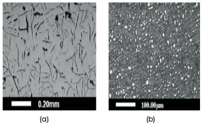
Figure 9. Microstructures of Two Different Disk Materials used in this experiment: (a) Gray iron, (b) Al-MMC
Figure 10 shows the specific wear rate calculated for all six friction couples. The wear tests were carried out with initial brake temperature of 100o C. The wear rate was normalized by friction energy and sliding distance. Tests were performed using friction materials that contained Cu fibers, steel fibers, and Al fibers on gray iron disks and Al-MMC disks. The value denoted by the symbol, the wear rate in the case of steel fiber friction material on Al-MMC was obtained before erratic frictional behavior showing excessive wear. The results show that the steel fiber friction materials exhibited greater wear when rubbed against both types of disks compared to the other two friction materials. It should also be noted that the specific wear rate for the Cu and Al fiber friction materials was virtually the same for both the gray iron and Al-MMC disks. This suggests that the friction film (or transfer layer) on the disk surface effectively prevents direct contacts between the friction material and counter disks and that the wear rate is determined by the type of metal fibers in the friction material (Jang, et al., 2004).
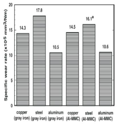
Figure 10. Specific Wear Rate of Friction Materials obtained from Wear Tests
This invention is concerned with a hybrid aluminum matrix composite material of particular use in the fabrication of lightweight brake components. In this context, the term “aluminium” embraces both aluminium and its alloys. It also includes certain magnesium alloys, which contain significant percentages of aluminium.
This article is concerned with hybrid aluminium matrix composite for use in the fabrication of brake parts, such as the rotating parts used in vehicle disc or drum brake systems. The fabrication of metal parts in which a combination of strength, improved wear resistance and acceptable resistance to elevated temperatures up to about 500o C is required to a level not currently attainable with the known aluminium alloys (Jason et al.,2003).
The following conclusions were drawn from the article.