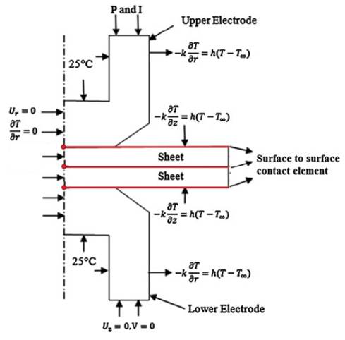
Figure 1. Boundary conditions used in the finite element model.
In this study, a finite element model and an artificial neural network model have been used to predict nugget size for resistance spot weld of AZ31 Mg alloy. The quality and strength of spot welds determine the integrity of the structure, which depends thoroughly on the nugget size. Different spot welding parameters such as the welding current, the welding time and electrode force were selected to be used for the FE (Finite Element) model. Although, the use of a finite-element analysis decreases the main costs associated with the nugget-size measurement tests; due to high complexity of a spot weld, its FE models are very time-consuming and requiring high-speed computers. So in this study, a FE model along with an Artificial Neural Network (ANN) has been adopted to predict the nugget size. The results obtained with the FE analysis were used to build up a back-propagation ANN model for the nugget-size prediction. The results revealed that a combination of these two developed models can accurately and rapidly predict the nugget size for a resistance spot weld of AZ31 Mg alloy.
Nowadays the use of lightweight materials in the automobile industry, and in transportation is very important because these substances are energy saving and produce fewer emissions. Accordingly, the use of Magnesium and its alloys are rising because it has a density of 2/3 of that of aluminum and 1/5 that of steel, high strength to density ratio and is easily recycled. Resistance Spot Welding (RSW) is one of the fastest methods of assembly and widely used in the automotive industry. The development factors of this type of welding can be used for a wide range of metals, high speed, low cost and has high potential for automation.
Typically, a modern automotive vehicle contains 2000– 5000 spot welds, and the joint quality and performance can dramatically alter the structural performance of vehicles, have a critical role in durability and safety design of vehicles [1]. During a resistance-welding operation, a workpiece is pressed between two electrodes and an electrical current is passed between the electrodes. Based on the Joule’ s law, the resistance in the electrode worksheet and worksheet-worksheet interfaces generates the heat that locally melts and binds the sheets together. The section, where the two pieces of metal melt and then cool down to form one piece is called a nugget. In fact, the nugget is that area that actually joins the two pieces of metal together. The quality and strength of spot welds in a structure determine the performance quality of that structure, depending thoroughly on the nugget size. Many factors such as welding current, welding time, electrode force, sheet thickness etc. control the size of the nugget. The nugget size should be larger than a certain volume to secure the strength of a welded joint. On the other hand, changing the parameters to obtain a very large nugget size leads to an explosion in the weld zone which reduces the strength of a welded joint. The nugget size is usually between 4 and 8.5 mm, completely depending on the sheet thickness. So, control of the welding parameters is necessary to obtain high weld quality and to increase a vehicle’s life [2].
Although there are many researches being carried out on the effects of welding parameters on the nugget size in spot welds of steels and many approaches being developed and recommended for a nugget-size prediction, the studies on Mg-alloy spot welds are scarce. In 2005, Wang, Feng and Zhang [3]perused surface quality effect on expulsion in RSW of AZ31 Mg alloy. The effects of current and surface quality were surveyed on the size, microstructure and straight of nugget in the spot welded Mg alloys joints [4]. Liu et al. [5- 6] investigated the effects of current, welding time and surface on the nugget size and mechanical properties of Mg alloys welded joints. In 2010, Shi et al. [7]investigated the feasibility of using cover plate for spot welding of AZ31 Mg alloy. Xiao, Liu, Zhou and Esmaeili [8-9] also in 2010 and 2011 studied on melting and solidification, microstructure and fatigue life of nugget. In 2011, Hwang, Kim and kang [10] investigated current source (DC and AC current) effects in RSW of Mg alloys. In recent years, Montiel, Liu, Xiao, Zhou and Provatas [11] studied the effects of welding parameters on microstructure, solidification and nugget plasticity in spot welding of AZ31 Mg sheet.
Although, the use of a finite-element analysis decreases the main costs associated with the nugget-size measurement tests; due to the high complexity of a spot weld, its FE models are very time-consuming and require high-speed computers. The method of Artificial Neural Networks (ANNs) is considered as an effective approach for solving non-linear problems. A quick learning ability and high-speed solutions of ANNs have led to a more extensive use of this method. In this research, a FE electro-thermomechanical and a back propagation ANN models were utilized to predict the nugget size in RSW of AZ31 Mg alloy.
The resistance spot welding process is a complex process which involves many different phenomena (e.g., mechanical, thermal, electrical, metallurgical, etc.). Due to this complexity and the extensive connections between these different fields, a simulation of this operation is very difficult and time-consuming. In this study, an axisymmetrically coupled, thermal-electrical-mechanical FE model was used for simulating a spot weld (Figure 1). To create the FE model, the commercial ANSYS12.1 software and the APDL (ANSYS Parametric Design Language) environment were used. To achieve a higher accuracy, temperature- dependent properties have been defined for the used material.
Figure 1. Boundary conditions used in the finite element model.
Figure 2 illustrates the solving algorithm of the finite-element model. As the figure presents, the first step of the welding process is the squeeze cycle. The initial mechanical analysis is used in this step to determine the initial deformation and the new contact-area shape. In the next step, the welding cycle, the electrical current is applied to the top surface of the upper electrode. The electrical current enters from higher face of upper electrode and after passing through the contact area between the electrode-sheet and sheet–sheet, arrives at the lower face of the bottom electrode to which, has been applied a zero electrical voltage. In this step, by using the thermalelectrical elements, the heat generation is calculated for each increment from the fully coupled model at the welding cycle.
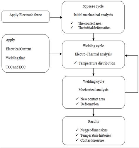
Figure 2. Flowchart of the finite-element solving algorithm [2].
The equations in this study are based upon a twodimensional cylindrical coordinate system. The governing equation for calculation of the electrical potential φ in the entire model is:
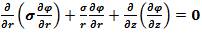
Where r is the radial distance, z is the distance in the axial direction, and Ce is the electrical conductivity. Based on Joule heat equation, the heat generation per unit volume, q, can be shown as:

Where t is the time and R is the material electrical resistance. The governing equation for transient temperature field distribution by considering heat due to electrical resistance heat can be presented as:
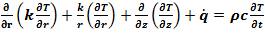
Where ρ is the material's density, C is the heat capacity, T is the temperature, and k is the thermal conductivity.
In Figure 1, all the boundary conditions of mechanical, electrical and thermal finite element model have been presented. Water temperature in the channel electrode is constant in all process cycle and has been considered at 25oC. Surfaces that are in contact with air have 12 Wm-2 /K convection coefficient [2].
In this study, a back-propagation ANN was employed to predict the nugget size for a spot weld. Structurally, every ANN is made up of three sections (Figure 3). The initial section corresponds to the input layer of an ANN. In the present study, the 3 main parameters, the welding current, the welding time and electrode force were used as the network inputs. The number of layers and neurons of the middle section, or the hidden layer, are determined with the trial-and-error method. The end section of the network is the output layer. In this study, the nugget diameter was used as the ANN output. The training algorithm of Levenberg- Marquad was employed to train the ANN. This training algorithm has a very quick learning speed [2]. The performance index used in the training was the Mean Squared Error (MSE) defined as:
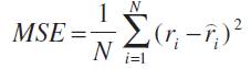
Where ri is the actual variable, while  is the estimated variable and N is the number of data samples. In the present study, the tolerance for MSE was selected as 0.0001.
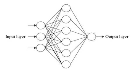
Figure 3. A typical artificial neural network
Figure 4 shows the steps of the nugget growth in the FE model. To validate the model, the nugget shapes in the FE model are compared to those obtained from the previous experimental test [10]. Figure 5 shows the temperature distribution at the end of the welding cycle. The contour of nugget is defined by considering 650oC as the melting point of the AZ31. As Figure 5 presents, the nugget diameter and height are in a good agreement with data obtained from experimental test. The difference between modeling and experimental results may be due to the shrinkage of the nugget as it cools down to room temperature after welding process. In addition, the FE model was run with 4 different sets of spot weld parameters and the results compared to those obtained from the experimental test [10]. Table 1 presents the results of this comparison and indicates that FE model can predict the nugget size with high accuracy.
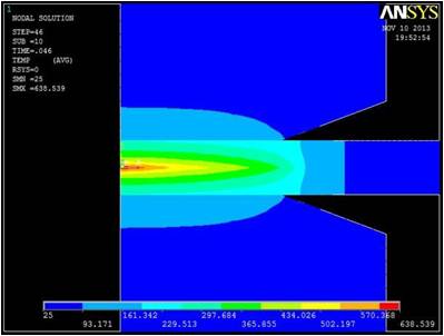
a. Welding time: 0.046 sec
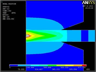
b. Welding time: 0.052 sec
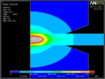
c. Welding time: 0.087 sec
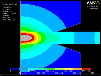
d. Welding time: 0.117 sec
Figure 4 Nugget development in FE Model.
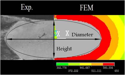
Figure 5. Comparing the shape of simulation nugget with metallographic experimental sample [10].
Based on the previous study [10], to secure the strength of a welded joint the nugget size should be more than 3.5mm and to avoid explosion in the weld zone it should be less than 6.0mm. Therefore, the selection of the spot-welding parameters is based on the simulation results of the FE analysis with the aim of achieving a weld-nugget diameter between 3.5 mm and 6.0 mm. Table 2 shows the selected spot-welding parameters obtained from the FEA for the nugget-size prediction with the ANN. Of the 52 sets of parameters presented in Table 2, seven samples were randomly selected and used for testing the ANN, and the remaining samples (45 samples) were used for training the ANN.
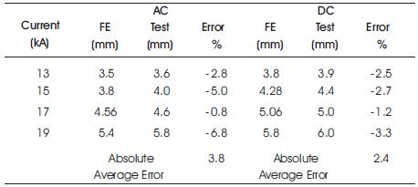
Table 1. Comparing the predicted nugget diameter with experimental data [10]
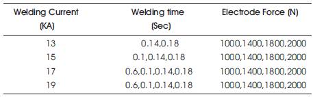
Table 2. The acceptable welding parameters obtained from FE model
By testing different structures of the ANN, it was determined that an ANN with one hidden layer and 5 neurons in this layer has the lowest error in the prediction of the nugget diameter. Figure 6 shows the results of training a developed ANN on the basis of the data obtained from the FE analysis. As this figure indicates, the presented ANN was well trained.
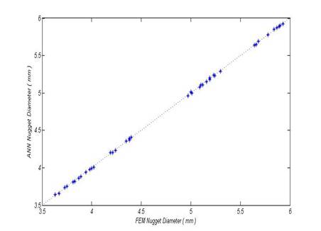
Figure 6. Comparing the FEM and ANN results for training data.
After training the created ANN, the network was tested by employing the 7 samples that had not been used in the training. The result of the testing is shown in Figure 7. The obtained results demonstrate that the created ANN has a good accuracy (less than 3 % of the absolute average error) in the prediction of the nugget diameter, based on the listed spot-welding parameters. So, this network can be used reliably for predicting the nugget diameter in the spot weld of AZ31 Mg alloy.
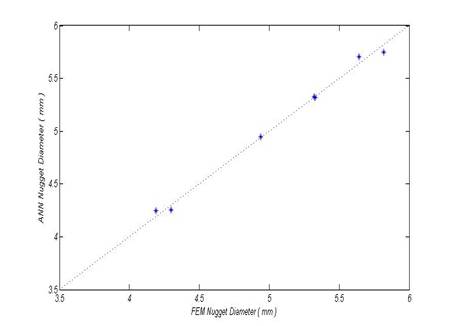
Figure 7. Comparing the FEM and ANN results for test data.
In this study, the nugget size for the spot weld of an AZ31 Mg alloy sheet with a thickness of 1 mm was predicted with a combination of a finite-element analysis and an artificial neural network. The comparison between the FEA results and the measured nugget size indicates that the presented FE model has good accuracy in the prediction of nugget size, and that by using this FE model, the distribution of temperature in spot welds can be investigated. Furthermore, the ANN model created by using the results of the FEA has very good accuracy (less than 3%) in the prediction of nugget size based on the spot welding parameters of welding current, welding time and electrode force. After validation of FEA and ANN results, through the use of FEA and ANN, the nugget size in spot welds can be well predicted, and there will be reduced high costs and can shorten time of experimental measurements tests. The results indicate that the ANN method can be easily utilized for prediction of the nugget's geometry and, therefore, quality of the welded joints.