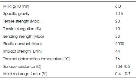
Table 1. Characteristics of (PS-M A-463)
Plastic materials have become the optimum choice for numerous industrial applications where the performance rather than cost is the prime consideration. The demand for the machining processes of plastics has recently increased. This work investigates the Electrical Discharge Machining (EDM) of PS-M A-463 plastic material with polystyrene base. The characteristics of PS-M A-463 plastic machined by EDM are studied in terms of machining parameters. Machining of plastics can be realized in EDM by assisting electrode method. In this method, the EDM workpiece surface is covered with an electrical conductive layer during discharge. The layer holds the electrical conductivity during discharging process. The workpiece surfaces were examined by Scanning Electron Microscopy (SEM). Moreover, surface roughness was determined with a Surface Profilometer. Experimental results indicate that the extent of delamination and surface roughness are proportional to the machining parameters. The EDM process effectively produces excellent surface characteristics and high quality holes in PS-M A-463 plastic material under low discharge energy conditions.
Recently, plastics have become the materials of choice for replacing metals, as they can offer many advantages. They are not generally subject to corrosion; they are light in weight, frequently with a good strength to weight ratio; they are very cost-effective giving greater design flexibility; and they have color ability (Rajput, 2008; Alauddin et al., 1995). Among structural materials employed in machine construction, plastics occupy one of the leading places. They are used for manufacturing ordinary and worm gears, bearings, pulleys, machine tool, slide ways and rollers. Thus, plastic plays an important role in many applications such as electrical and electronic industry in addition to the aircraft, rocket, automobile, aerospace, light industries, food, offshore drilling, marine and a variety of specialized industries (Kalpakjian et al., 2009 ; Lantos, 1987; Weber, 1991).
Plastic materials by nature are very good electrical insulators. But, plastics can be made electrically conductive by adding conductive fillers or additives or combination of both. High aspect ratio fillers (whose length-to-diameter ratio is much greater than unity) excel in forming conductive networks, preserve properties and keep the surface smooth, while being electrically conductive to meet enough specifications. Plastic materials are often machined to create prototypes, production parts that cannot be molded, or finish parts that have been molded for improved dimensional and size accuracies. Thermoplastics are low strength and hardness type materials that permit high machine cutting speeds and feeds, but the low heat conductivity and greater resilience require increased reliefs and less rake in order to avoid undersize cutting. Hard and sharp machine tools should be used. Plastics sometimes contain abrasives that can cause the machine tools to wear or become dull rapidly. Dull machine tools generate heat and cause the tools to cut to shallow depths or increase material flow. The depth and force applied by the machine tool should be small. When high production justifies the cost, diamond turning and boring tools are used. Diamond tools maintain sharp cutting edges and produce an excellent machined surface. They are particularly advantageous when more abrasive plastics such as reinforced plastics is machined (Rajput, 2008; Alauddin et al., 1995; Kalpakjian et al., 2009). Two types of plastics are being used in manufacturing. These are plain plastics in cast conditions or laminated plastics. Plastics face problems such as heating and edge fretting when machined. During the machining process, plastic material is removed in fine particles and in some cases gases may also evolve in chips, which are harmful and hence must be removed immediately (Rajput, 2008).
While comparing with common machining metals, plastics appear to be soft and easy to be machined. Some plastics are abrasive and wear away cutting tools very quickly, while others are flexible and require very precise machining to achieve proper feature size. The traditional methods for machining and fabricating of plastic materials mainly depend on the proprietary experience enabling precision plastic machining. It can be die-cut on standard diecutting machines. All secondary operations are possible, including: machining, sawing, shearing, drilling, punching and polishing (Alauddin et al., 1995). However, much of the proprietary experience enabling precision plastics machining has been developed in small, privately held plastics machining operations. There are some problems faced by the operator when conventionally machining the plastic such as it needs to be carefully supported and requires large rake and relief angles, high cutting speed and low feed (Kalpakjian et al., 2009). There are some studies in the literature that are focused on the influence of the machining parameters during drilling of composites materials made of thermoplastics on the machining quality and the wear of the tools (Kim, et al. 2005; Zitoune et al. 2013; Krishnaraj et al. 2014). Improper machining with the wrong holding tools, cutting tools, coolant, or manufacturing process can prevent the part from meeting all the design requirements. It can also lead to premature product failure (Rajput, 2008; Toshihiko et al., 2005; Bhatnagar et al., 1995; Koplev et al., 1983). Also, plastic materials and its composites can be machined by nontraditional methods of machining such as electrochemical arc machining, ultrasonic, laser, water jet cutting, and abrasive water jet cutting processes (Tandon et al., 1990; Wuthrich et al., 2005; Wang, 1999; Seo et al., 2004; Takeyama, 1988).
Electrical discharge machining is one of the non-traditional methods. Thermoelectric machining methods are capable of machining the parts of hard material accurately into complex shapes and it is mostly done with the aid of a numerically controlled machine (Rajput, 2008). In this process there is no direct contact between the tool electrode and the workpiece where thermal energy is utilized to remove the material from the workpiece (Toshihiko et al., 2005). In conventional EDM, erosion of material from the work piece is accomplished by series of discrete sparks maintained between the work and the tool electrode which is immersed in a fluid dielectric medium (Alauddin et al., 1995). These electrical discharges melt and vaporize minute amount of work material, which are then ejected and flushed away by the dielectric. EDM is a widespread technique used in industries for high-precision machining of all types of conductive material such as: metals, metallic alloys, graphite, or even some ceramic materials, of any hardness (Rajput, 2008). The electrode is positioned at a fixed small distance above the workpiece, both submerged in a dielectric fluid. The gap is stabilized by the servo control unit mechanism. In the closest distance between the tool and workpiece, spark is produced and the machining process begins (Hascalik and Caydas, 2004). Luis et al. (2005) concluded that by using EDM method conductive and semi conductive materials can be machined. Machining in different directions and angles does not require fixtures which is the main advantage of this approach. The machinability of workpiece materials by electrical discharge machining is a function of electrical resistivity and the melting point of it. It does not depend on the hardness and strength of the workpiece material. The required electrical resistivity of the material to be machined by EDM process must be less than 100 Ω cm (Ebied et al., 2004; Amarasekera, 2005; Tani et al., 2004) .
Many researchers were interested in EDM machining of every type of conductive materials such as steel, stainless steel, aluminum alloys (Khan, 2008; ReBelo et al., 2000; Lim et al., 1991; Patel et al., 2012; Atefi et al., 2012). Other researchers also investigated the EDM process for conductive and non-conductive ceramics and composites(Koplev et al., 1983; Bhatnagar et al., 1995; Jain et al., 2002; Konig et al., 1988; Mutamara et al., 2003; Kozak et al., 2004). The cutting parameters required and the machining conditions for these materials were also studied. But available literature on EDM processing of plastic material is scanty. Thus, in this work an attempt was made to machine PS-M A-463 plastic material with polystyrene base by EDM process. The study investigates the characteristics of EDM machined surfaces and the effects of processing variables on the drilled hole cavity quality, delamination and surface roughness.
In this section, the equipment used to perform EDM experiments and surface integrity analysis are described, and also the properties and dimensions of workpiece and tool electrode have been mentioned.
The experiments were carried out using a numerical control programming electrical discharge machine known as "R50-EZNC". The dielectric fluid used for the experiments was kerosene. Different settings of four controllable factors such as pulse-on, peak current, electrode rotational speed and average machining voltage were used in the experiments. Also, the electrode polarity was positive when using graphite electrodes and the negative polarity was used with copper electrodes.
The surface finish value Ra (μm) was obtained by measuring the mean absolute deviation from the average surface level using Mitutoyo Talysurf (SJ-201) portable surface measuring unit. Among various parameters available in the surface measuring instrument, the parameter Ra is considered in the present study. The cutoff length for each measurement was taken as 0.8 mm. Keyence VE-8800 Scanning Electron Microscopy (SEM) is used to study the morphology of the EDMed surface and the recast layer in a cross section of the machined surface.
The workpiece materials used in this work were plastic material (PS-M A-463) manufactured by Dainichiseika Color Chemicals Mfg. Co. Ltd, Japan and SKD11 tool steel. The physical and mechanical characteristics of PS-M A-463 plastic material are shown in Table 1. The workpieces of plastic material that were used in the experiments were prepared as a parallelogram with dimensions of 100 mm in length, 50 mm in width and 3 mm thickness. The tool electrodes made of cylindrical copper and graphite (ED-3) with 8 mm diameter were used. The selected EDM machining conditions and setting parameters are listed in Table 2.
In this work the assisting electrode method was used as the plastic materials are very good electrical insulators. In the assisting electrode method, it is assumed that the machining process proceeds with two discharge phenomena. The first, on one hand, it is responsible for generating the electrically conductive products on the surface of the workpiece and the second, on the other hand, it is responsible for actual machining of the workpiece (Tani et al., 2004). Figure 1 shows that a sheet of steel structure (JIS G 3101 - SS400) of 1.0 mm thickness was used as an assisting electrode material over the workpiece (plastic) material. JIS G 3101 - SS400 is one of the most commonly used hot rolled general structural steel. The surface of the insulating plastic is covered in advance with a conductive material such as SS400. This layer on the plastic surface takes the role of the assisting electrode. During the machining process, the workpiece is covered with the assisting electrode material which is dipped in kerosene oil.
Table 1. Characteristics of (PS-M A-463)
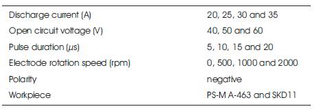
Table 2. EDM machining conditions
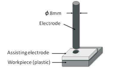
Figure 1. Schematic drawing of the EDM experiment
PS-M A-463 plastic workpieces were EDM machined using both copper and graphite electrodes. The capability of the plastic material to be machined by electrical discharge machining process was tested by measuring the hole quality, delamination factor, surface roughness and surface morphology of drilled cavities while varying the input variables. The input variables selected for this study were pulse duration, discharge current, average voltage and tool-electrode rotation of the electrode. Experimental results of electrical discharge machining demonstrate that typical cavities were drilled in both the assisting electrode and the workpiece (plastic material) together as shown in Figure 2. A sample of the experimental shape of the resulted drilled cavities in the PS-M A-463 plastic material is shown in Figure 3. During this work, the electrode polarity was selected to be negative. Normally, negative polarity of electrodes is selected when using EDM on insulating materials due to the need for the generation of a conductive layer during the machining process (Mohri et al., 1996; Fukuzawa et al., 1997; Fukuzawa et al., 2004). Carbon in the working oil can easily generate a conductive layer on the workpiece material's surface (Mohri et al., 2003).
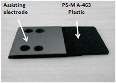
Figure 2. Experimental shape of assisting electrode and workpiece together after EDM machining.
Figure 4 shows the micrographs of EDM machined hole cavities’ shapes of PS-MA-463 plastic. It summarizes the effects of pulse-on duration, tool-electrode rotation, pulse current and average machining voltage on the hole edge damage produced by 8.0 mm diameter using both copper and graphite electrodes. Figure 4 also shows that the resulted cavities have good circularity shapes. Unfortunately, the dimension accuracy of the drilled cavities was found bad, where the machining area of the resulted hole was extremely one and half times that of the used solid tool-electrode. The surface of the workpiece closest to the tool-electrode in EDM is subjected to a temperature rise of up to 40000 K (DiBitonto et al., 1989). During electrical discharge machining of plastic material, the upper material in the extremely high temperature region will vaporize, while the lower material will melt and expand. When the machining operation was finished, the melted material was cooled rapidly taking the new expanded shape. Also, some smaller pockets were found around the cavities. During EDM processing, working conditions can influence the incidence of tear-like or delamination damages.
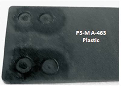
Figure 3. Experimental shape of drilled cavities resulted in the plastic workpiece after EDM machining.
When applying the smaller peak current 20A, average machining voltage of 60V and the pulse-on duration 10 μs with no electrode rotation, the hole quality was good and no machining damage was observed in the plastic laminate surface. However, as the peak current, pulse-on duration and electrode rotation speed increase, the delamination damage could increase. Also, as average machining voltage decreased, the damage could increase. Such damage extends far beyond the thermally influenced area and into the base material, causing stress concentration along the holes, and eventually decreasing the service strength.
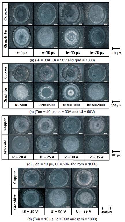
Figure 4. Micrographs of EDMed surfaces of PS-M A-463 plastic by copper and graphite electrodes related to (a). pulse-on duration, (b). tool-electrode rotation, (c). peak current and (d). average machining voltage.
During the electrical discharge machining process, the electrical discharge sparks produce extremely high temperature which rapidly vaporizes the dielectric fluid and creates pressure impulses around the tool-electrode. The impact pressure and high thermal stresses generated by the discharge sparks produce the delamination in the machining surface around the resulted hole cavities. The extent of delamination can be determined according to two or three methods (using diameter, or damaged area...). In this work, the delamination factor can be computed by measuring the maximum hole diameter in the damage zone as shown in Figure 5.
The delamination factor is proposed to facilitate analysis of the delamination degree in comparison with different machining conditions. The delamination factor is defined as:
Df = dmax/d
where Df denotes the delamination factor, dmax represents the maximum diameter of the damage zone, and d is the hole diameter.
Figure 6 shows the correlation between the delamination factor and machining parameters for the EDM machining of the plastic material. The delamination factor clearly increases with the energy supply. This increase occurs because the impulse force increases with increasing discharge energy, thus increasing the delamination degree.
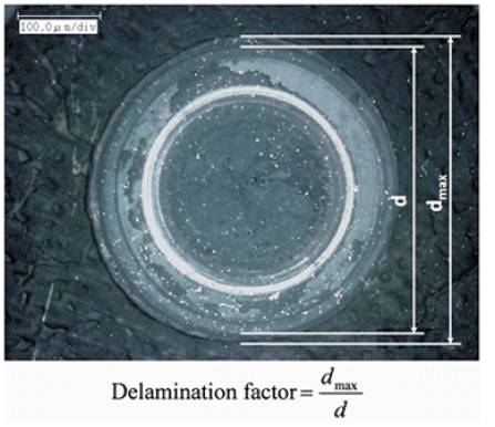
Figure 5. Estimation of the Delamination Factor (Ton = 10 μs, Ie = 30A, Ui = 50V and rpm = 500)
The relation between delamination factor and pulse duration for EDM machining of PS-MA-463 plastic and SKD11 materials are shown in Figure 6-a. The delamination factor increases with pulse duration when machining plastic materials by copper or graphite tool-electrodes. Delamination factor for SKD11 was extremely constant with the increase of pulse duration. The delamination factor values of the machined cavities for plastic material are higher than those values for SKD11. During electrical discharge machining process of plastic material, the workpiece was directed to heating to elevated temperatures and thus some of the plastic grains were vaporized and the others were expanded. The thermal expansion is upto 10 times greater with plastic materials than metals. When the PS-M A-463 workpiece was cooled, the expanded plastic grains did not return to its original shapes as SKD11 tool steel. Thus plastic material will take a bigger shape.
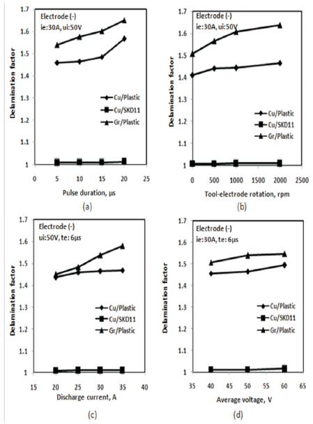
Figure 6. Variations of delamination factor with machining parameters of PS-M A-463 plastic and SKD11.
To confirm the effects of tool-electrode rotation on the delamination factor, Figure 6-b shows the relation between delamination factor and tool-electrode rotation using copper and graphite electrodes. All of the EDM processes for PS-M A-463 plastic and SKD11 were carried out using four different tool-electrode rotations of 0, 500, 1000 and 2000 rpm. As the tool-electrode rotation was increased from 0 to 2000 rpm, the delamination factor for plastic material increased from 1.41125 to 1.465 using copper electrodes and from 1.5075 to 1.63875 using graphite electrodes. On the other hand, the delamination factor increased from 1.009211 to 1.01071 for SKD11 for the same increase of tool-electrode rotation. The centrifugal forces resulted from tool-electrode rotation increases the delamination factor. During EDM processes, the expanded grains of SKD11 tool steel return rapidly to its original shape than the plastic materials.
Figure 6-c shows the relation between delamination factor and peak current for plastic and SKD11 machined by copper and graphite tool-electrodes. As the peak current increases, the energy of spark increases and hence more heating leads to increase of the delamination factor. The relation between delamination factor and average machining voltage is shown in Figure 6-d. As the average machining voltage is increased the delamination factor is increased, probably due to the decrease in conductivity of the PS-M A-463 plastic material.
Figure 7 displays the SEM micrographs of the machined surfaces formed at a normal discharge by both copper and graphite tool-electrodes of the PS-MA-463 plastic material. During EDM processing with copper toolelectrode, the surface characteristics are relatively smooth. However, when machining with graphite toolelectrode, the machined surface shows irregular valleys, with deeper and longer craters which are formed by the electrical discharge channel. Another prominent feature on EDM surfaces of plastic material is the abundance of microcracks. These cracks are seen to radiate from, and also to circumvent, the craters. The crater sizes increase with pulse energy. As it does, the density of surface cracks. Electrical discharge machining process erodes surfaces randomly. To determine the effect of the EDM on the surface roughness of plastic material, this study measured the surface profiles of the topography of the EDM surfaces. Figure 8 shows the measurement results as a function of the machining parameters.
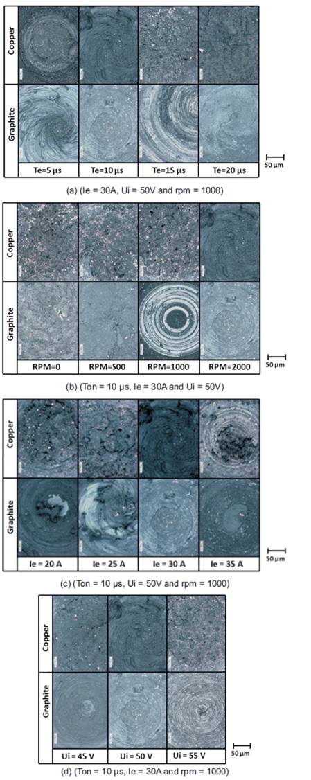
Figure 7. Micrographs of EDMed surfaces finish by copper and graphite electrodes related to (a) pulse-on duration, (b) tool-electrode rotation, (c) peak current and (d) average machining voltage.
The surface roughness of plastic material increases with pulse duration. Also, the surface roughness values of drilled cavities of plastic material by graphite electrodes are smaller than that by copper electrodes but three times larger than that for SKD11 material.
Pulse duration is defined as the time during which the machining is performed. The machining process becomes faster after increasing the pulse duration. By increasing the pulse duration, poor surface finish on the material surface resulted (Lee et al., 2003). As the pulse duration increases, the pulse energy also increases and thus the amount of intense heat is increased causing crater globules of debris, and pockmarks formed on the workpiece surface due to the entrapped gases escaping from the re-deposited material. With each discharge, a crater is formed on the workpiece and a smaller crater is formed on the tool electrode. During EDM machining of plastic materials by copper and graphite electrodes, a large amount of plastic was melted rapidly due to its lower melting point and after removal of heat, it lost heat more slowly than metals leaving large craters in its surface. Long pulses mean a large quantity of energy transferred to the plastic material, which produces very large craters and thus the surface roughness values increases.
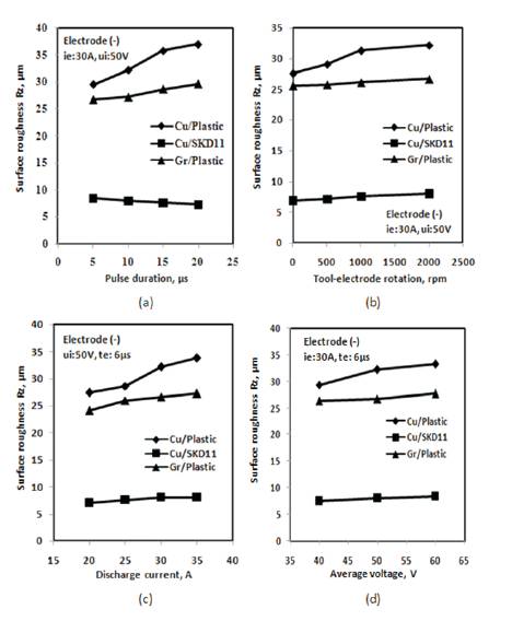
Figure 8. Variations of surface roughness with machining parameters of PS-M A-463 plastic and SKD11.
Clearly, a poorer surface finish is obtained with higher pulse current. During each electrical discharge, intense heat is generated, causing local melting or even evaporation of the workpiece material. With each discharge, a crater is formed on the workpiece and a smaller crater is formed on the tool electrode (Tani et al., 2004). Due to high pulse current, the spark intensity and discharge power are more, subsequently causing a large crater depth on the surface of the work piece, which resulted in high surface roughness. Also, increasing tool-electrode rotation increases the movement of the heated dielectric fluid over the plastic grains leading to more irregular valleys and thus bad surface finish. On the other hand, an increase in voltage implies higher discharge energy applied between the two electrodes as well as increased the rate of gas bubbles formation, resulting in poor surface finish of the plastic material. An excellent machined finish can be obtained by setting the machine parameters at small pulse-on duration, no electrode rotation, low pulse currents and relatively higher values of average machining voltage.
The electrical discharge machining parameters of PS-M A- 463 plastic material were investigated by using the assisting electrode method which led to the following conclusions: