Figure 1. Ultrasonic Testing Machine
This paper summarizes some of the major aspects of precision ultrasonic thickness gauging. Ultrasonic NonDestructive Testing (NDT) characterizing material thickness, integrity, or other physical properties by means of high-frequency sound waves has become a widely used technique for quality control. In thickness gauging, ultrasonic techniques permit quick and reliable measurement of thickness without requiring access to both sides of a part. During the thickness measurement of any corroded plate, the reading of ultrasonic equipment gives many different readings for each time of inspection at same position due to their non uniform surfaces. Due to corrosion of metal piece, a material whose thickness is lower than the low limit of the probe causes measurement errors. Sometimes the displayed reading is twice as big as the actual thickness. To prevent these errors, the critical thin materials should be measured repeatedly for verification. This paper looks at the review causes of poor performance with ultrasonic techniques and suggests some methods to improve the situation.
Corrosion is one of the serious problem affecting ship, pipe line and aviation industries. It affects the body of ship and thickness of pipe and an aeroplane wings, surface, between joints and fasteners. The presence of corrosion underneath the paints of surface and between joints cannot be detected easily. The unnoticed presence of corrosion may cause so many accidents leading to human and money loses. To detect the thickness of the metal surface, various methods and tests are used. These tests conducted should be such that, it does not destroy or disassemble the equipment parts or damage its surface. Hence for the further use of the equipment, Non- Destructive Tests (NDT) are carried out.
Non-destructive testing is a testing procedure that does not cause any damage to the part being tested. The various non-destructive testing methods used are:
1)Visual inspection
2) X-ray inspection
3) Die (liquid) penetration inspection
4) Magnetic particle inspection
5) Eddy current inspection
6) Ultrasonic inspection
Ultrasonic inspection is conventionally used for thickness measurement of ship plate, pipe line and aviation industries. But the conventional inspection method has certain defects:
These defects can be overwhelmed by a newly developed inspection method using guided ultrasonic waves
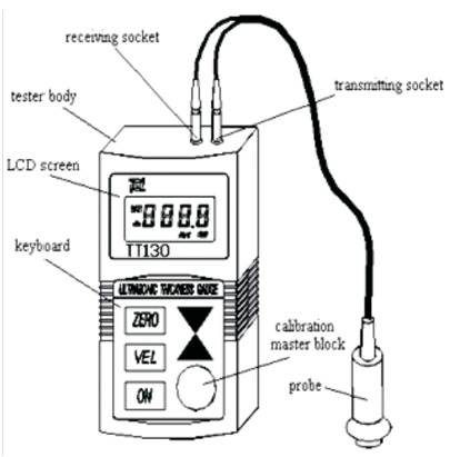
Guided waves demonstrate an attractive solution where conventional ultrasonic inspection techniques are less sensitive to defects such as corrosion/disbonds in thin multilayered wing skin structures and hidden exfoliation under wing skin fasteners. Moreover, with their multimode character, selection of guided wave modes can be optimized for detection of particular types of defects. Mode optimization can be done by selecting modes with maximum group velocities (minimum dispersion), or analysis of their wave mode structures (particle displacements, stresses and power distributions). Figure 1 shows Ultrasonic Testing Machine.
Figure 1. Ultrasonic Testing Machine
Ultrasonic NonDestructive Testing (NDT) characterizing material thickness, integrity, or other physical properties by means of high-frequency sound waves-has become a widely used technique for quality control. In thickness gauging, ultrasonic techniques permit quick and reliable measurement of thickness without requiring access to both sides of a part. Accuracies as high as ±1 micron or ±0.0001 inch are achievable in some applications. Most engineering materials can be measured ultrasonically, including metals, plastic, ceramics, composites, epoxies, and glass, as well as liquid levels and the thickness of certain biological specimens. On-line or in-process measurement of extruded plastics or rolled metal is often possible, as the measurement is carried out in single layer or coatings in multilayer materials. Modern hand held gauges are simple to use and highly reliable.
Precision ultrasonic thickness gauges usually operate at frequencies between 500 KHz and 100 MHZ, using piezoelectric transducers to generate bursts of sound waves when excited by electrical pulses. A wide variety of transducers with various acoustic characteristics have been developed to meet the needs of industrial applications. Typically, lower frequencies will be used to optimize penetration when measuring thicker, highly attenuating, or highly scattering materials, while higher frequencies will be recommended to optimize resolution in thinner, non-attenuating, non-scattering materials.
A pulse-echo ultrasonic thickness gauge determines the thickness of a part or structure by accurately measuring the time required for a short ultrasonic pulse generated by a transducer to travel through the thickness of the material, which reflects back and returns to the transducer. In most applications this time interval is only a few microseconds or less. The measured two-way transit time is divided by two to account for the down-and-back travel path, and then multiplied by the velocity of sound in the test material. The result is expressed in a well-known relationship:
Additionally, in actual practice, a zero offset is usually subtracted from the measured time interval to account for certain fixed electronic and mechanical delays. In common case of measurements, involving direct contact transducers, the zero offset compensates for the transit time of the sound pulse through the transducer's wear plate and the couplant layer, as well as any electronic switching time or cable delays. Figure 2 shows the principle of Ultrasonic Testing Machine. This zero offset is set as a part of instrument calibration procedures and is necessary for highest accuracy and linearity.
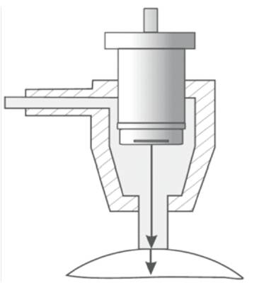
Figure 2. Principle of Ultrasonic Testing Machine
The accuracy of any ultrasonic measurement is similar as to the accuracy and care with which the gauge has been calibrated. All quality ultrasonic gauges provide a method for calibrating the sound velocity and zero offset appropriate for the application at hand. It is essential that this calibration has to be performed periodically and checked in accordance with the manufacturer's instructions. Sound velocity must always be set with respect to the material being measured. Zero offset is usually related to the type of transducer, cable length of the transducer and mode of measurement being used.
Rusty spots and eroded pits may cause the readings to change irregularly. Under extreme circumstances, there is even no reading. It is hard to discover a small rusty spot. When a eroded pit is found or is in suspicion, care is needed to measure the area. The different angle positions of the probe cross talk isolating board may be selected to carry measurements for many times.
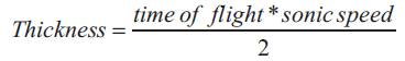
Figure 3. Path of Ultrasonic wave
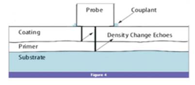
Figure 4. Layers of test material with ultrasonic probe
The best measurement accuracy is obtained when both the front and back surfaces of the test piece are smooth and parallel. If the contact surface is rough, the minimum thickness can get increased because of sound reverberating in the increased thickness of the couplant layer. There will also be potential inaccuracy caused by variations in the thickness of the couplant layer beneath the transducer. Additionally, if either surface of the test piece is rough, the returning echo may be distorted due to the multiplicity of slightly different sound paths seen by the transducer, and measurement inaccuracies will result.
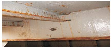
Figure 5. internal surface of ship hull structure after 5year
The instrument provides many measuring methods.
The probe is used to measure any point of the work piece to be measured and display the thickness value.
Perform two measurements on the same point of the measured surface, in the second measurement, splitting plane of the probe should be 90 degree, taking minimum as the thickness value.
Perform several measurements in a circle about 30mm in diameter and take the minimum value as the thickness value.
Apply the single point measurement method, and take measurements continuously along the designated route, the intervals should be less than 5mm, and take the minimum value as the work piece's thickness.
In Mode 1 (direct contact transducer) measurements, the couplant layer thickness is part of the measurement and is compensated by a portion of the zero offset. If maximum accuracy is to be achieved, the coupling technique must be consistent. This is accomplished by using a couplant of reasonably low viscosity, employing only enough couplant to achieve a reasonable reading, and applying the transducer with uniform pressure. A little practice will show the degree of moderate to firm pressure that produces repeatable readings. In general, smaller diameter transducers require less coupling force to squeeze out the excess couplant than larger diameter transducers. In all modes, tilting the transducer will distort echoes and cause inaccurate readings, as noted below.
A related issue involves the alignment of the transducer with respect to the test piece. When measuring on curved surfaces, it is important that the transducer should be placed approximately on the centerline of the part and held as nearly normal to the surface as possible [4,5]. In some cases a spring-loaded V-block holder may be helpful for maintaining this alignment. In general, as the radius of curvature decreases, the size of the transducer should be reduced, thus becoming more critical for transducer alignment. For smaller radius, an immersion approach will be necessary. In some cases, it may be useful to observe the waveform display via an oscilloscope or other waveform display as an aid in maintaining optimum alignment. Often practice with the aid of a waveform display will give the operator a proper "feel" for the best way to hold the transducer. On curved surfaces it is important to use only enough couplant to obtain a reading. Excess couplant will form a fillet between the transducer and the test surface where sound will reverberate and possibly create spurious signals that may trigger false readings.
If the contact surface and back surface of the test piece are tapered or eccentric with respect to each other, the return echo will be distorted due to the variation in sound path across the width of the beam. Accuracy of measurement will be reduced. In severe cases no measurement will be possible.
Engineering materials that can potentially limit the accuracy and range of ultrasonic thickness measurements:
In materials such as cast stainless steel, cast iron, fiberglass, and composites, sound energy will be scattered from individual crystallites in casting or boundaries of dissimilar materials within the fiberglass or composite. Porosity in any material can have the same effect. Gauge sensitivity must be adjusted to prevent detection of these spurious scatter echoes. This compensation can in turn limit the ability to discriminate a valid return echo from the back side of the material, thereby restricting measurement range.
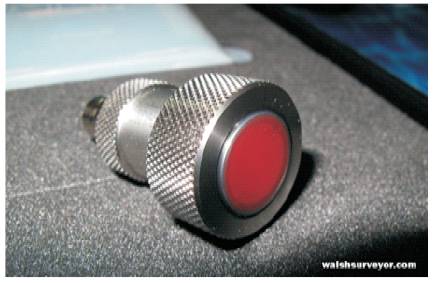
Figure 6. Ultrasonic thickness measuring Equipment Probe
In many organic materials such as low density plastics and rubber, sound energy is attenuated very rapidly at the frequencies used for ultrasonic gauging. This attenuation typically increases with temperature. The maximum thickness that can be measured in these materials will often be limited by attenuation.
An ultrasonic thickness measurement will be accurate only to the degree that material sound velocity is consistent with gauge calibration. Some materials exhibit significant variations in sound velocity from point to point. This happens in certain cast metals due to the changes in grain structure that result from varied cooling rates, and the anisotropy of sound velocity with respect to grain structure. Fiberglass can show localized velocity variations due to changes in resin/fiber ratio. Many plastics and rubbers show a rapid change in sound velocity with temperature, requiring that velocity calibration be performed at the temperature where measurements are to be made. velocity of ultrasonic sound in different materials given in Table 1.
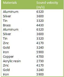
Table 1. Velocity of Different Materials
The phase or polarity of a returning echo is determined by the relative acoustic impedances (density x velocity) of the boundary materials. Most commercial gages assume the customary situation where the test piece is backed by air or a liquid, both of which have lower acoustic impedances than metals, ceramics, or plastics. However, in some specialized cases (such as measurement of glass or plastic liners over metal, or copper cladding over steel) this impedance relationship is reversed, and the echo appears phase reversed. To maintain accuracy in these cases it is necessary to change the appropriate Echo Detection polarity, or on instruments where that are not possible, adjust the zero offset to compensate for a timing error equal to one-half cycle of the waveform.
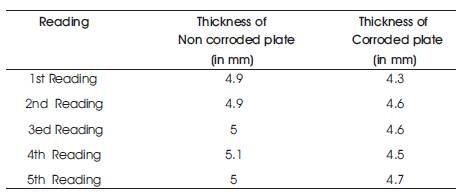
Table 2. Comparatively study of 5mm thick plate before and after corrosion
Any material whose thickness is lower than the low limit of the probe will cause measurement errors. instrument should be connected again for measuring the same material in order to obtain the result of the minimum thickness. in measuring super-thin materials, there might be such erroneous results as “dual deflection” sometimes. that means that the displayed reading is twice as big as the actual thickness. another error is known as “pulse envelope, cyclic jumping”. The result is bigger than the actual thickness. to prevent these errors, the critical thin materials should be measured repeatedly for verification.
Though the device has been corrected by one material, there is still mistake when measuring another materials, so proper sound velocity should be selected.
The probe surface is made of acrylic resin shown in the fig 6. After using for a long times, the roughness may increase, thus causing the sensitivity declines. If it has been determined that the error is caused by roughness, the sand paper or oil grinding stone may be used to grind the surface of the probe so that it will become smooth and parallel. If the reading is still unstable, the probe must be replaced.
Dense oxide layer may be found in some metals, such as aluminum etc [6]. This oxide layer contacts with the substrate tightly without clear interface. But ultrasonic wave transmits with different velocities in these two materials, which will cause measurement error. Different thickness of oxide layer will result in different measurement errors. It should be cautious to deal with this kind of situation. It's applicable to select one block of testing material as sample, measure its thickness by vernier caliper or micrometer and use this sample to calibrate the gauge.
Operators should have the ability of identifying abnormal readings. Usually, rusty Sports, corroded pits and the interior flaws of the test materials can all cause abnormal readings. For solution, see chapter 9 and 10 of this manual.
Coupling agent is used for transmitting high frequency ultrasonic energy between the probe and the test material. Incorrect selection of the types of coupling agents or improper usage may cause errors or flashing of the coupling sign, making it unable to measure the thickness. Coupling agent should be used in proper amount and coated evenly.
It is important to select the proper type of coupling agents. When the surface of the test material is smooth, low viscosity coupling agent should be used (coupling agents and light machine oil are provided with the instrument). High viscosity coupling agents (such as glycerin paste and lubricating fat etc.) may be chosen for rough surface or vertical surface or peak surface.
A more complex situation can occur in corrode metal sheet, where material conditions result in the existence of multiple sound paths within the beam area. In these cases phase distortion can create an echo that is neither cleanly positive nor negative. Careful experimentation with reference standards is necessary in these cases to determine measurement accuracy. If the effect is consistent it will usually be possible to compensate by means of a zero offset adjustment, but if echo shape is variable, highly accurate thickness measurements may not be possible.
If we ignore the error of corrosion pitting, the performance characteristics of our probes and use an ultrasonic technique not more suited to finished product thickness measurement, we are likely to reduce probability of error of measurement and sacrifice measurement accuracy.
Here the authors have some observation of calibrated ultrasonic thickness gauge(CYGNUS II)[ 7] over the non corroded versus corroded metal plate of mild steel 5mm thick plate after the effected with three month open environmental corrosion condition (Table 2).
Thus in the case of corroded metal plate the lowest reading should be considered on measurement for the better safety condition for design.
Techniques which are most suitable for reducing the error in measurement of thickness can be summarized by following lines:
The use of above techniques can improve probability of better thickness measurement and careful considerations of the relevant defect and also can optimize measurement accuracy.