Figure 1. Scheme of Cup Drawing Process
The cup drawing process of sheet takes an important place in forming metals. The traditional techniques of tool design for sheet forming operations used in industry are experimental and expensive methods. Prediction of the forming results, determination of the punching force, blank holder forces and the thickness distribution of the sheet metal will decrease the production cost and time of the material to be formed. In this project, cup drawing simulation has been presented with finite element method. The entire production step has been simulated by ANSYS 15.0 software under axisymmetric conditions with nonlinear Transient dynamic analysis. Radial, axial, hoop and Von Mises stress patterns have been simulated for critical load conditions. A rigorous analysis of Von Mises stress has been performed to track the yield behavior of blank. Contact behavior was also observed. Simulated Punch force was compared with experimental values for different travel intervals.
A very often used sheet metal forming process is deep drawing process. Parameters such as blank-holder pressure, punch radius, die radius, material properties, and coefficient of friction affect deep drawing process. So, a great knowledge of process is required to produce product without wrinkling and such other defects. Further the process may be performed in one-step drawing or multi-steps. Multi-step drawing processes are usually applied to forming parts that have geometrical complexity or formability problems and cannot be formed by one -step forming. In those cases, one of the most critical and challenging issues is to determine minimum required forming steps and the corresponding part shapes in any forming steps. Singh and Agnihotri (2015) highlighted the importance of each of these process parameters in their paper. Arab and Javadimanesh (2013) published their paper on theoretical and experimental analysis carried out on deep drawing of cylindrical cup. They said that in deep drawing of cylindrical cup, the deformation in the flange is dominated by pure shear deformation, while it changes to plane strain when the material is drawn into the die. Marumo, Saiki, and Ruan (2007) paper indicates the need for variation in the blank holding force for the elimination of wrinkling. The blank holding force required for the elimination of wrinkling increased rapidly for smaller sheet thickness. Limiting the drawing ratio is often found as a parameter indicating the effectiveness of draw ability. Kumar and Reddy (2016) performed tests where a circular blank drawn into conical cup until the fracture is occurred at the bottom of cup by using of flat cylindrical punch and without using the blank holder pressure. The base diameter of fracture conical cup is used to determination of diametrical ratio.
Numerical simulation of Deep drawing process has often been a good rescue to analysis of the process which is very complex. Shakil, Hamed, and Chamekh (2015) simulated the single stage deep drawing process of a steel cup using specifications close to industrial specifications. Their study included effect of key parameters on deformed cup thickness, punch reaction force and equivalent plastic strain. Understanding the stress distribution pattern is often helpful. Anwekar and Jain (2012) also simulated the single stage deep drawing process of thin walled, mild steel, conical back plate of radial impeller of blowers by means of a finite element analysis. Simulation of the drawing process for determining stress distribution in the drawn component is explained in the presented work. Anaraki, Shahabizadeh, and Babaee (2012); Magar and Khire (2010) did the finite element analysis for multi stage deep drawing process using ABAQUS. The simulation results such as sheet thickness distribution, punch force and residual stresses have been extracted and compared with experimental results. Kumar, Kumar, and Abhimaan (2015) analyzed the deep drawing process using ANSYS for the behaviour of deep drawing of aluminium alloys in the temperature range 200-500°C. Trivedi, Joshi, and Patel (2015) described the simulation of shallow drawing process using DEFORM. Loads simulated were compared with experimental results for different materials.
On account of multiple variables affecting the performance of deep drawing process, optimization methods also have been applied. Joshi, Patil, Satao, and Chandrababu (2014) investigated effect of die draw radius, sheet thickness and blank holder force on the variation in wall thickness of a deep drawn cup using finite element simulations. The variation in wall thickness is minimized by carrying out analysis of variance (ANOVA) for individual factors and their interactions. Using TAGUCHI's signal-to-noise ratio, it is determined that the punch nose radius has major influence followed by blank holder pressure and punch pressure on the thickness distribution of the deep drawn cup of Stainless Steel AISI 202 sheet, was investigated by Kumar, Tanveer, Makwana, and Sivakumar (2013).
Other methods of nontraditional forming have been performed to improve the drawing process. Ramezani and Neitzert (2013) gave a overview of a deep drawing process by pressurized liquid medium separated from the sheet by a rubber diaphragm. The Hydroforming deep drawing processing of sheet metal parts showed an increased depth to diameter ratio possible in cup drawing and minimizes the thickness variation of the drawn cup. Dhaiban, Soliman, and El-Sebaie (2013) performed production of elliptical cups in single-acting stroke. The effects of blank thickness and clearance ratio on limiting drawing ratio, drawing load and thickness strain were also experimentally investigated.
The traditional sheet plate forming techniques used in industry are experimental, expensive and time-consuming. Prediction of the formability, thickness distribution in deep drawing process will decrease the production cost and time of material to be formed. Hence in the present work, the finite element transient dynamic analysis of cup drawing process is carried out, unveiling the stress pattern during the deformation process, at different time steps. To ensure the appropriateness of analysis, the intensity of stress responsible for yielding was also watched. The load pattern was also tracked.
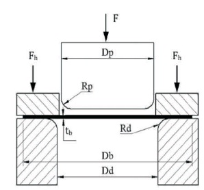
The drawing operation mainly involves pushing the blank gradually into the cavity of the forming die by the punch to be formed into the required shape. Another tool named blank holder is usually used to hold the flange portion of the blank down against die shoulder.
Figure 1 shows simple cup drawing operation of a cylindrical cup with the basic parameters. A rigid punch with a diameter (Dp) and nose radius (Rp) applies a drawing force (F) on a circular blank with initial diameter (Db) and thickness (tb). Usually the blank is pressed into a die cavity with a corner radius (Rd) and is held down at the flange porting by the blank holder force (Fh). It can be observed h that if the corners of the forming punch are sharp (Rp and Rd =0) then a cutting operation would be performed rather than a drawing operation. Also, it is essential to adopt a clearance between the sidewalls of the punch and the die cavity. This clearance is usually about 10% greater than the initial thickness of the blank used.
Figure 1. Scheme of Cup Drawing Process
Cold metal working of Aluminum 1100 is performed for many different products, including chemical equipment, railroad tank cars, fin stock, dials, name plates, cooking utensils, rivets, reflectors and sheet metal. The plumbing and lighting industries also use Aluminum 1100, as do a wide variety of other industries. The properties of Al 1100 used in this experimentation are specified Table 1.
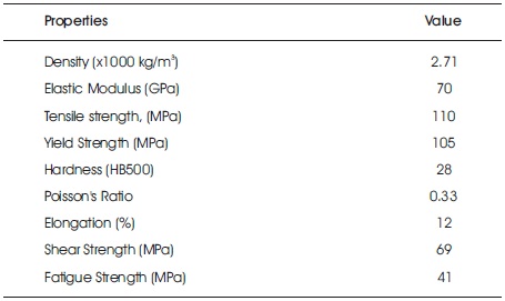
Table 1. Material Properties of Aluminum 1100
In this experiment, circular-cups have been formed from circular blanks using a test rig installed on a FIE universal testing machine of 1000 KN capacity. The drawing force is applied continuously at fixed strain rate. No lubrication was used between blank, die and punch.
Figure 2 shows the cup drawing die set parts, which mainly consists of punch, die-holder and die. The punch has been fixed to the upper head while die was fixed up to the lower head. Alignment has been carried out for proper striking and ensuring uniform clearance between the punch and the die aperture. Air vent has been provided for preventing vacuum and associated releasing difficulties. The die consists of 11.5 mm land and 5.2 mm die radius. The die has long wall which is larger than land to facilitate disposal of drawn cups. At the fixed jaw, a dial indicator is attached to record the punch force with respect to punch travel. This setup is shown in Figure 3.
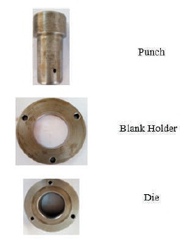
Figure 2. Dieset Parts: Punch-Blank Holder - Die
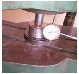
Figure 3. UTM Setup used for Drawing Process
In the modelling of the cup-drawing process many complexities are encountered such as non-linearity, elasto-plastic transformations and non-constant boundary conditions of contact with friction. Proper selection of element type, elementsize, and modelling variables is hence crucial for the validity of the model. The above rich capabilities of ANSYS 15.0 FEA software has been used for simulating the cup drawing process. The blank is discretized using SOLID 185 element. The contact surfaces such as punch-blank, blank-blank holder and blank-die are modeled using contact elements. The contact pair was modelled with TARGE 170 and CONTA174 contact elements. The tools were treated as rigid materials while blank was treated as a deformable material. In this analysis, applying loads and boundary conditions consist of defining which parts move in geometrical model. The geometry model of punch, blank, die and die holder assembly is shown in Figure 4. Contact surfaces used in the presented work are top of blank - bottom of punch, bottom of blank – top of die. The movement of blank part under punch is restricted in x- direction. The part of the blank which is not in contact initially with die is given displacement in y-direction. Movement of horizontal part of the blank, which is on the die, is restricted in x- direction as well as in y-direction.
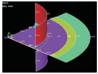
Figure 4. Assembly of a Punch, Blank, Die and Die Holder
Figures 5 and 6 display the meshed blank in quarter size since the blank and tools are axisymmetric. Hence the meshing and analysis was carried two dimensional geometry.

Figure 5. The Blank with SOLID 185 Mesh
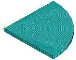
Figure 6. Meshed Plate of Quarter Shape
Figure 7 shows the stress distributions for 10 mm of punch travel. This travel has been considered because the load was observed to be highest at this instant. Figure 7a shows the radial stress distribution. It is observed that the shell bottom exhibits highest radial stress compared with walls and the corner. It is felt that this is responsible for thinning of the bottom. A highest value of 120 N/mm2 is observed which is slightly larger than the yield stress. Figure 7b shows the axial stress distribution. It is seen that this component of stress is highest in shell wall. This contributes to the pushing of the shell into the die opening. A peak value of 97.8 N/mm2 of this stress is seen. Figure 7c shows the hoop stress distribution. The highest value observed is 98 N/mm2. This stress contributes to stretching or wrapping around the punch. Figure 7d shows the shear xy stress. This stress is found to show its peak value around the shell corner. Hence this component has contributed to wrapping of material around the punch corner. Figure 7e shows the Von Mises stress pattern in the shell. This component is held responsible to initiate yielding of material or the plastic flow. This stress is the sum effect of all the above stresses mentioned. The largest value of this stress is observed to be 109 N/mm2 which indicates that yielding has taken place. Noting that material yield strength is105 N/mm2, the shell shape shall retain. Figure 7f displays all the stresses on die blank from centre to the end for punch travel of 10 mm.
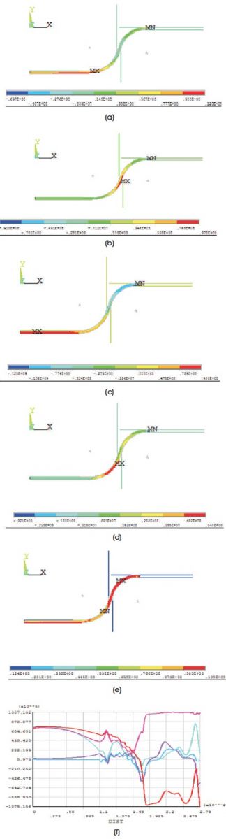
Figure 7. (a) X-direction Stress at Punch Travel 10 mm, (b) Y- direction Stress at Punch Travel 10 mm, (c) Z- direction Stress at Punch Travel 10 mm, (d) XY Shear Stress at Punch Travel at 10 mm, (e) Von Mises Stress at Punch Travel 10 mm, (f) All the Stresses on Die Blank from Centre to the End for Punch Travel 10 mm
Figure 8a, and 8b shows the contact condition of the shell with punch and die. Figure 8a shows the contact status with respect to the condition that sticking or sliding or near contact. It is seen that severe contact is present at die corner (sliding) and punch corner (sticking). The sticking condition exhibited at the punch corner hints a subsurface flow of work material. This condition can be influential in affecting the finished surface around the shell corner. Figure 8b indicates that contact pressures exhibited at die and punch corners are predominant. This pressure is relatively uniform around punch corner while spikes are observed around the die corner where the bend of blank commences.
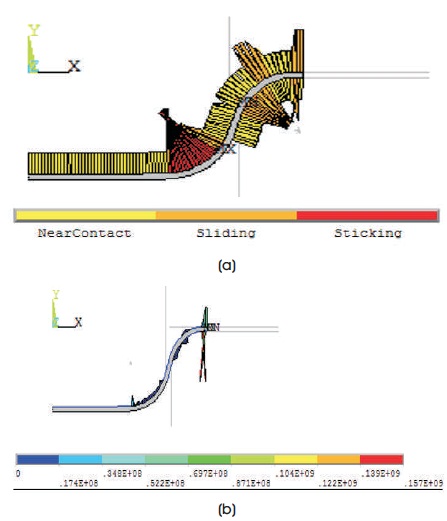
Figure 8. (a) Contact Status at Punch Travel 10 mm, (b) Contact Pressure at Punch Travel 10 mm
Figure 9a shows the intermediate shape of shell for a punch descent of 5 mm. The observations are :
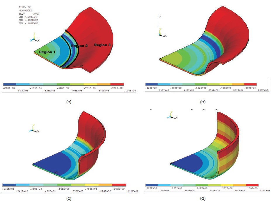
Figure 9. (a) Deformed Cup Shape at Punch Travel 5 mm, (b) Deformed Cup Shape at Punch Travel 10 mm (c) Deformed Cup Shape at Punch Travel 15 mm, (d) Deformed Cup Shape at Punch Travel 20 mm
Region 1 where the Von Mises stress decreases from a value of 61.5 N/mm2 to 25.8 N/mm2. Region where the stress increases from the value of 25.8 2 2 N/mm2 to 61.5 N/mm2 at punch corner partial contact and again decreases to the value of 25.8 N/mm2.
Region 3 where the stress increases from 25.8 N/mm2 to 106 N/mm2 till the rim of the cup. The underside of the cup is an exception where the stress is larger and at about 106 N/mm2. This can also mean that surface flow at the outer of the shell is more severe.
Figure 9b shows the Von Mises stress in the cup at another intermediate position of punch ie, 10mm. The observations made for these decent of the punch are similar to that of 5 mm decent. The Region 2 is not as clear as with previous case. In addition, it may be identified that the bottom (Region 1) experiences 50% decrease in stress. The underside of the cup experiences again a yield stress while around the punch corner the stress is released slightly. Figure 9c shows the Von Mises stress in the cup at another intermediate position of punch, i.e.15 mm. Region 1 experiences an increase in stress against what has happened in cases of descents seen above. Region 2 again experiences a mixed stress pattern. Region 3 continues to experience a similar stress pattern that has been experienced in previous cases of descent. Figure 9(d) shows the Von Mises stress in the cup at near end of cup drawing i.e. 20 mm descent. The shell is almost straight-walled, and all the regions experience a release of stress which is appropriate at this near end of drawing process.
Figure 10 show the variation of load as punch travels. It is observed from the plot that load is not uniform throughout the length of stroke. The load increases until a peak value and further declines. It may be expected that initially load is required to bend/ wrap the blank around the punch. In later stages, force is also required to push the wrapped cup against the die walls. Hence, the total load changes, depending on contribution of these component forces, causing the bending and later straightening. Some amount of force is also used to cause change in thickness of the shell bottom and walls.

Figure 10. Load Vs Punch Travel
The Finite element simulation performed has uncovered interesting behavior of metal flow into the die and transforming into a cup of desired dimensions. The pattern of different component stresses shows a controlled flow of material into die opening. The tracking of Von Mises stress component made clear that the deformation is not hypothetical and permanent. The comparison of punch travel vs load pattern with experimental values shows the degree of correctness of ANSYS solution. The analysis may be extended to further complicated conditions such as use of lubricated interfaces and anisotropy. The contact behavior shows sliding as well as sticking regions indicating both full and subsurface flows. Hence the estimate of surface finish on the blank can be also carried out in future studies.