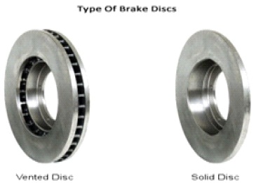
Figure 1. Type of Disc Brake Rotors
Safety is always associated with the effective usage of the braking phenomenon of the automobiles. Disc brakes in fourwheelers compared to solid disc type, ventilated disc brake rotor design helps to cool down the disc from heat generated due to friction with the air vents provided. Frictional heat generation in disc brake which leads to severe negative effects, i.e. thermal cracks, brake fade, premature wear, rotor disc thickness variation, etc. So, the precision of temperature distribution and geometry of the disc brake rotor plays a key role in cooling factor of the disc brake and squeal noise generation during braking also plays a major role in deciding the effectiveness of a disc brake with respect to brake fade. In this study, by changing the geometry of the disc brake rotors is to analyze the thermo-mechanical behaviour of the solid and ventilated disc brakes and using the coupled transient thermal and static structural analysis is performed using Finite Element Methods with the help of ANSYS. It is used to determine the temperature, deformation, stresses, and strain fields established in various models of disc brake rotors. Computational Fluid Dynamics (CFD) analysis is performed to investigate the wall heat transfer coefficient of ventilated disc brake rotors using ANSYS Fluent software. From the above CFD analysis, due to changing of vane shapes, there is a considerable increase (10.25%) in modified straight rectangular vane compared to the rectangular vane in heat transfer coefficient of the rotor. Finally, modal analysis is performed using ANSYS to check the disc brake squeal. By comparing the parameters, i.e. temperature, stress distribution is validated with the analytical results, and thereby the optimized or best disc brake rotor is proposed for the effective usage of braking operation of a four-wheeler.
A brake is a mechanical device by means of which applying external resistance to the moving machine element to stop the motion of the vehicle.
The system of disc brake consists of a brake rotor, brake pads, and brake caliper. The disc brake is a brake that operates by the action of a frictional material, i.e. pads pressed against the sides of a rotating disc by a brake caliper to stop the rotation of the wheel. The main principle of disc brake based on the converting kinetic energy is developed by the moving machine member into the heat energy. The essential components of disc brake are brake pads, brake caliper, brake rotor.
The brake rotor is a rotating part of disc brake assembly, which is mounted to the hub, against which the pads are applied to stop the vehicle. In braking operation, when a brake is applied, brake pads wear out over time, the rotor also undergoes some wear in the form of ridges or groves.
Majorly, the disc brakes are available drilled and slotted in nature because mainly when brake pads rub against the rotor, it created friction, which generates heat. If this heat does not escape, it leads to brake fade. So brake rotor having drilled holes, makes it easy for heat, gas, water to be quickly moved away from the rotor and maintain the effectiveness of braking.
Based on the geometry of disc brake rotor, disc brakes are divided into mainly two types, i.e. solid disc brake and ventilated disc brakes as shown in Figure 1. Compared to solid disc type, ventilated disc brake design helps to cool down the disc from heat generated due to friction with the air vents provided.
Figure 1. Type of Disc Brake Rotors
Belhocine and Bouchetara (2013) investigated on full and ventilated disc brake using a thermo-mechanical coupling model to determine the temperature and thermal stress using ANSYS computing code. In this study, the entering parameters concerned at the time of braking such as the geometric design of the disc brake rotor, type of braking are considered and the used material affects the temperature distribution. Adamowicz and Grzes (2011b) evaluated the convective mode of heat transfer on the braking process, i.e. thermal behavior of braking system during repetitive braking process with the constant velocity using a three-dimensional finite element model. Alnaqi, Barton, and Brooks (2015) proposed an experimentation based on a scaling methodology to evaluate the thermal performance of a disc brake at a reduced scale. The resulting small-scale implies reduced development time and the advantage of low cost. Kubota, Hamabe, Nakazono, Fukuda, amd Doi (2000) stated that essential requirements for effective braking operating of a disc brake rotor, include high cooling, heat resistance, and less vibration. McPhee and Johnson (2008) conducted that experimental and analytical method to better understand convection through the vents of the brake rotor. Adamowicz and Grzes (2011a) compared the temperature distributions caused by mutual sliding of the disc brake rotor. Hwang, Wu, and Jeon (2009) determined the thermal stress, temperature distribution, thermal distortion in a solid disc by three-dimensional modeling for the repeated braking process. In the repeated braking process in order to stimulate accurate frictional heat behavior, the moving heat source is defined by space and time. Sakamoto (2004) investigated that cooling efficiency of ventilated disc brake rotors is based on the basic equation of heat convection and measurements of the volume flow through the fins. Predrag et al. (2010) reported that not only to achieve proper braking power for the braking system, but also heat dissipation to the environment in a braking system, which is very important for effective braking operation. Triches Jr, Gerges, and Jordan (2004) investigated on a reduction of the squeal noise generation from disc brakes using the addition of a constrained layer to brake pads by means of introducing additional damping to the braking system. Nakatsuji Okubo, Fujii, Sasada, and Noguchi (2002) suggested the effective methods for reducing tiny cracks around the holes of the disc brake rotor and analyzed the temperature distribution in overloading condition using the finite element method.
From the specialized literature review, it is observed that the precision of temperature distribution and geometry of the disc brake rotor plays a key role in cooling factor of the disc brake and also squeal noise generation during braking also plays a major role in deciding the effectiveness of a disc brake with respect to brake fade.
In this study, to control the temperature distribution and thermal stresses, solid disc brake rotor is modelled by already existing circular holes replaced with elliptical holes and also proposed the different type of vane arrangements on the ventilated rotor disc and also modal analysis is performed to control the squeal noise generation of the disc brake rotor.
The sequence of steps to be followed in designing and simulating the suggested disc brake rotors are as follows.
Standard dimensions, i.e. Figure 2 is taken from the certified brake catalogue. From the 2017 Brake catalogue of Maruti Swift Dzire Ldi (1248cc).
From Figure 2, A = Brake disc outer diameter = 256 mm
B = Thickness of disc = 22 mm
C =Minimum thickness of disc=20 mm
D = Hub thickness = 40 mm
E = Hub hole diameter = 60 mm
F = Radius of Fillet of Hub = 4 mm
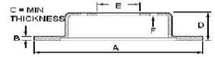
Figure 2. Dimensions of the Disc Brake Rotor
Grey cast iron is the most suitable or commonly used material for brake rotor because of its thermo-mechanical properties. So using the one of the grades of Grey Cast iron, i.e. FG150 is to perform the different type of analysis. Here 150 is the ultimate tensile strength of Grey Cast Iron in MPa.
Modelling of the modified type of solid and ventilated disc brake rotors, i.e. Figures 3 - 8 are modelled using CATIA V5R21 software.
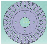
Figure 3. Solid Circular
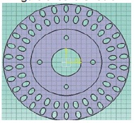
Figure 4. Solid Elliptical
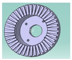
Figure 5. Ventilated
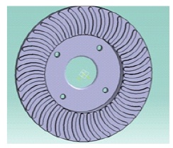
Figure 6. Ventilated Rectangular Circular
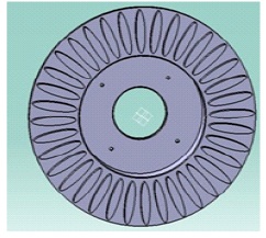
Figure 7. Ventilated
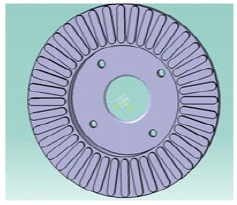
Figure 8.Ventilated Elliptical Modified Straight Rectangular (MSRV)
The Couple field analysis, i.e. transient thermal and static structural analysis is performed using Finite Element Method (FEM) with the help of ANSYS Workbench 15.
Initial Conditions: According to experimental tests, evoked o in literature review T (x, y, z) = 50 C at time t=0
Ambient Temperature = 27 oC
Boundary Conditions: These are calculated from the inputs of the standards of the specified car.
Stopping Distance (S.D) of Vehicle: Distance between when the brake fully applied to when it comes to complete stop.
The Transient thermal analysis is used to analyse the temperature distribution for a single stop event for a particular braking time of a solid disc brake rotors and ventilated disc brake rotors.
From Figure 10, it is observed that in transient thermal analysis, circular holes in the solid disc brake rotor raises the maximum temperature distribution 187.3 oC
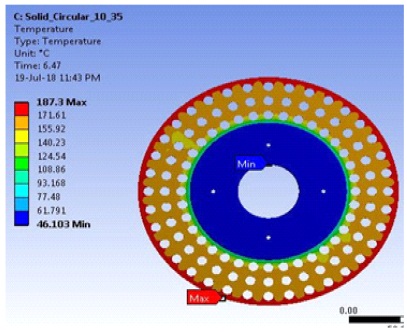
Figure 10. Solid Circular
From Figure 11, it is observed that in transient thermal analysis, elliptical holes in the solid disc brake rotor raises the maximum temperature distribution of 174.6 oC for a given braking time. But compared to Figure 10, it was less because of the change in geometry of the design of disc brake rotor.
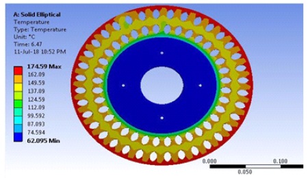
Figure 11. Solid Elliptical
From Figure 12, it is observed that in transient thermal analysis, rectangular vanes (Figure 5) in the ventilated disc brake rotor raises the maximum temperature distribution of 166.15 oC. But it is very less compared to solid disc brake rotor because of the change in geometry of the rotor helps to cool the disc brake rotor by passing the air as a fluid.
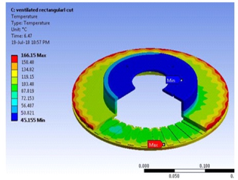
Figure 12. Ventilated Rectangular
From Figure 13, it is observed that in transient thermal analysis, circular cut type of vanes (Figure 6) in the ventilated disc brake rotor raises the maximum temperature distribution of 170.1 oC. It is quite high compared to rectangular vanes in a ventilated disc brake rotor.
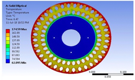
Figure 13. Ventilated Circular
From Figure 14, it is observed that in transient thermal analysis, elliptical cut type of vanes (Figure 7) in the ventilated disc brake rotor raises the maximum temperature distribution of 161.93 oC. It is less compared to rectangular and circular cut type of vanes in the ventilated disc brake rotor.
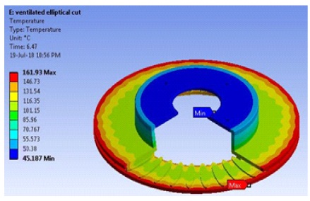
Figure 14. Ventilated Elliptical
From Figure 15, it is observed that in transient thermal analysis, MSRV type of vanes (Figure 8) in the ventilated disc brake rotor raises the maximum temperature distribution of 153.01 oC. It is very less compared to the other type of ventilated disc brake rotor because of a slight change in the design of disc brake rotor compared to existing ones; it affects maximum temperature generated due to the sudden braking condition in braking time of 6.47 s.
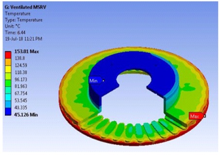
Figure 15. Ventilated MSRV
The static structural analysis is done to analyze deformation, von-misses stress and strain development over the disc brake rotor using the thermal load in the transient thermal analysis as input and fixing the load on the hub of the disc brake rotor.
From Figure 16, it is observed that in static structural analysis, circular holes in the solid disc brake rotor gives the maximum equivalent stress of 231.83 Mpa.
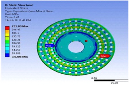
Figure 16. Solid Circular
From Figure 17, it is observed that in static structural analysis, elliptical holes in the solid disc brake rotor gives the maximum equivalent stress of 199.1MPa. The maximum equivalent stress developed in the solid elliptical disc brake rotor is 13.33% less than that of the solid circular disc brake rotor because of the change in hole shape of the disc brake rotor.
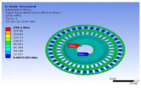
Figure 17. Solid Elliptical
From Figure 18, it is observed that in static structural analysis, rectangular type of vanes in the ventilated disc brake rotor gives the maximum equivalent stress of 81.76 MPa. It is very less compared to solid disc brake.
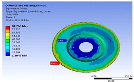
Figure 18. Ventilated Rectangular
From Figure 19, it is observed that in static structural analysis, circular cut type of vanes in the ventilated disc brake rotor gives the maximum equivalent stress is 100.79 MPa. It is high compared to the ventilated rectangular disc brake rotor.
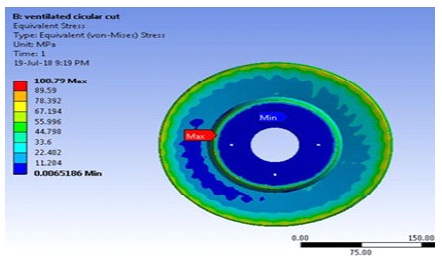
Figure 19. Ventilated Circular
From Figure 20, it is observed that in static structural analysis, elliptical cut type of vanes in the ventilated disc brake rotor gives the maximum equivalent stress of 110.41MPa.
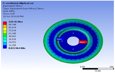
Figure 20. Ventilated Elliptical
From Figure 21, it is observed that in static structural analysis, MSRV type of vanes in the ventilated disc brake rotor gives the maximum equivalent stress of 75.32MPa. It is very less compared to the other ventilated disc brake rotors. So in the total simulation of single stop braking time, there is a significant equivalent stress variation in solid disc brake rotor and ventilated disc brake rotor.
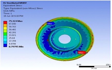
Figure 21. Ventilated MSRV
From the analytical calculations, it was observed that maximum temperature in a given disc brake rotor is 198 oC, From Table 1, all values of maximum temperature from couple-field analysis using finite element methods are under the analytical values.
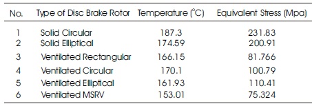
Table 1. Obtained Values from Coupled Field Analysis
Due to change in the design of disc brake rotor, there is a maximum temperature developed in the braking phase of solid elliptical disc brake rotor is 13 oC less than that of solid circular disc brake rotor and also maximum equivalent stress developed in the solid elliptical disc brake rotor is 13.33% less than that of solid circular disc brake rotor. Modified straight rectangular vane disc brake rotor have less equivalent stress, i.e. 75.324 MPa compared to the other ventilated and solid disc brake rotors. So, the design of disc brake rotor plays a key role in deciding the life of the disc brake.
In Figure 22, on the x-axis the numerical represents the various types of disc brake rotors as mentioned in Table 1. From Figure 22, it is concluded that the temperature distribution of the solid disc brake rotor is very high compared to the ventilated disc brake rotor. In the different type of vane arrangements of the ventilated disc brake, Modified straight radial vane type of disc brake rotor has reduced in temperature, i.e. 34 oC which plays a very significant role in cooling factor of the disc brake rotor.
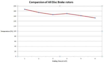
Figure 22. Temperature vs. All Disc Brake Rotors
Computational Fluid Dynamics (CFD) analysis is performed on the different type of ventilated disc brake rotors using ANSYS Fluent software. Forced convection takes place on the contact surface during every rotation of a disc, so a Forced convection situation is assumed here. The rotor is exposed to air flowing around at a constant velocity. The objective is to find out wall heat transfer coefficient of the component at a constant heat flux on the rotor of a disc brake.
The fluid domain is created as shown in Figure 23 around the disc brake rotor representing the atmosphere. As the disc is symmetric about both the axis, the quarter disc model provides a reasonably correct solution with a decrease in the solver time. Tetragonal type of meshing with fine size was used. Fine mesh is obtained by the use of proximity and curvature in ANSYS ICEM CFD as shown in Figure 24.
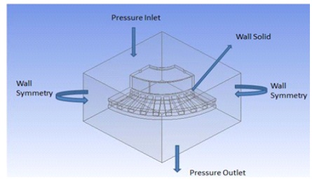
Figure 23. Modeling Part in CFD Fluent
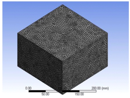
Figure 24. Meshing
Assumptions made for CFD analysis are as follows
In the present simulation, the flow fields are calculated by solving the Standard k- epsilon (ε) turbulence model.It is the most common model used in Computational Fluid Dynamics (CFD) to simulate mean flow characteristics for turbulent flow conditions. Symmetric quarter model of ventilated disc brake rotor is exposed to cold air flowing around at a constant speed.
Initial Conditions:
Considering the standard ambient conditions for temperature as
T (x,y,z) = 27 oC at time t = 0
Boundary Conditions:
Velocity of the disc brake rotor = 44.44 m/s
Heat flux applied to the rotor surface=153800 W/m2
4.1 Sectional Plane View of Contour Plots Of Wall Heat Transfer Coefficient (W/m2K)
From Figure 25, it is observed that in CFD analysis rectangular type of vanes in the ventilated disc brake rotor gives the wall heat transfer coefficient of 175 W/m2K.
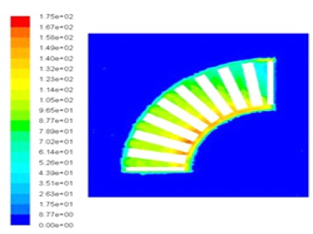
Figure 25. Ventilated Rectangular
From Figure 26, it i's observed that in CFD analysis, circular type of vanes in the ventilated disc brake rotor gives the wall 2 heat transfer coefficient of 184 W/m2K.
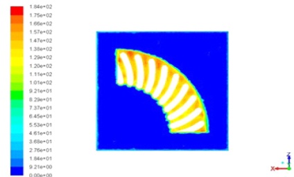
Figure 26. Ventilated Circular
From Figure 27, it is observed that in CFD analysis, elliptical vanes in the ventilated disc brake rotor gives the wall heat transfer coefficient of 178 W/m2K.
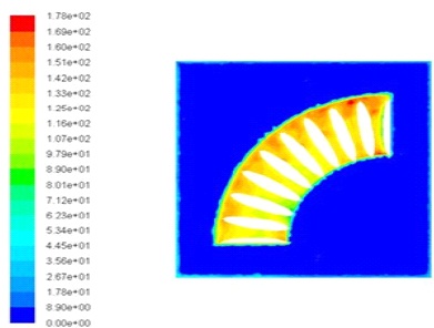
Figure 27. Ventilated Elliptical
From Figure 28, it is observed that in CFD analysis, MSRV type of vanes in the ventilated disc brake rotor gives the wall heat transfer coefficient of 195 W/m2K. From the above CFD analysis, it is showed the variation in wall heat transfer coefficient of various surfaces by varying the vane shapes of ventilated disc brake rotors with constant speed and heat flux.
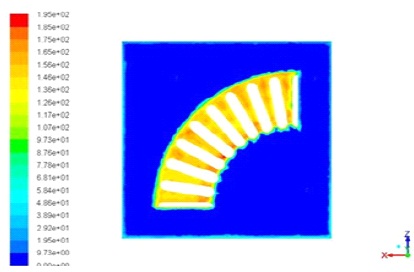
Figure 28. Ventilated MSRV
From Table 2, it is observed that wall heat transfer coefficient values obtained from Computational Fluid dynamics under the value of analytical value, i.e. 202.16 W/m2K.
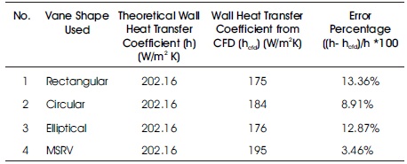
Table 2. Obtained Values from CFD Analysis
On x-axis of Figure 29, numerical values represent
From Figure 29, it is observed that Ventilated Modified Straight Rectangular Vane (MSRV) have less (3.46%) error percentage compared to the other ventilated disc brake rotors. Due to changing of vane shapes, there is considerable increase (10.25%) in modified straight rectangular vane compared to rectangular vane in heat transfer coefficient of the rotor.
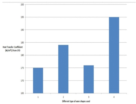
Figure 29. Heat Transfer Coefficient VS Different Type of Ventilated Disc Brake rotors
Squeal or modal analysis is used to determine the vibration characteristics, i.e. natural frequencies and mode shapes of a machine component. Normally in the braking phase, if the brake becomes very hot, it loses its efficiency. It was called a brake fade, which leads to brake squeal and produces high-frequency noise above 1kHz, is known as a squeal.
From Figure 30, it is observed that in modal analysis, circular holes in the solid disc brake rotor using FG150 material gives the mode 8 shape as 2681.8 Hz.
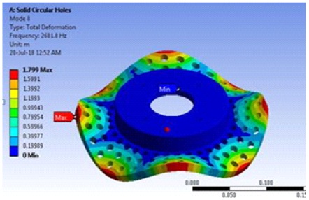
Figure 30. Solid Circular (FG150)
From Figure 31, it is observed that in modal analysis, elliptical holes in the solid disc brake rotor using FG150 material gives the mode 8 shape as 3701.3 Hz.
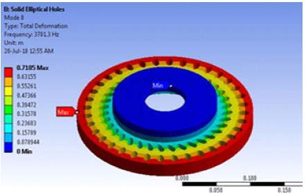
Figure 31. Solid Elliptical (FG150)
From Figure 32, it is observed that in modal analysis, MSRV type of vanes in the ventilated disc brake rotor using FG150 material gives the mode 8 shape as 3206.3 Hz.
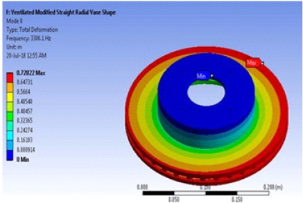
Figure 32. Ventilated MSRV (FG150)
From Figure 33, it is observed that in modal analysis, circular holes in the solid disc brake rotor using stainless steel material gives the mode 8 shape as 3379.5 Hz.
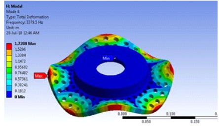
Figure 33. Solid Circular (Stainless Steel)
From Figure 34, It is observed that in modal analysis, elliptical holes in the solid disc brake rotor using stainless steel material gives the mode 8 shape as 4796.1 Hz.
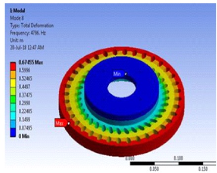
Figure 34. Solid Elliptical (Stainless Steel)
From Figure 35, it is observed that in modal analysis, MSRV type of vanes in the ventilated disc brake rotor using stainless steel material gives the mode 8 shape as 4215.1 Hz. From above, the modal analysis for solid circular and elliptical disc brake rotors and ventilated modified straight rectangular vane disc brake rotor (best one from the couple field and CFD analysis) with 8 mode shapes was performed using ANSYS Workbench 15 to check the disc brake squeal for the given materials.
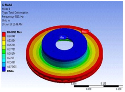
Figure 35. Ventilated MSRV (Stainless Steel)
In the modal analysis, it is showed that the values from the simulation are within the low squeal frequency 1 kHz to 7 kHz. So it was safe to use the braking application.
From Table 3, it is observed that lowest squeal found in solid circular disc brake compared to other disc brake rotors. Solid circular disc brake rotor using FG150 material have less squeal compared to other material in the modal analysis.
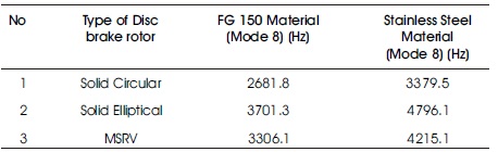
Table 3. Obtained Values from Modal Analysis
From the Couple Field Analysis, it is observed that in all disc brake rotors, deformations are found to be decreasing from outer edge to inner edge. The maximum equivalent stress developed in the solid elliptical disc brake rotor is 13.33% less than that of the solid circular disc brake rotor.
Modified straight rectangular vane disc brake rotor having less equivalent stress, i.e. 75.324 MPa compared to the other ventilated and solid disc brake rotors. In the total simulation of single stop braking time, there is a significant variation in solid disc brake rotor and ventilated disc brake rotor.
All obtained simulation results are under the analytical values. So, the disc brake rotor design is under the limits of the permissible range. So, by comparing all disc brake rotors, modified straight rectangular vane plays a significant role in the cooling of the disc, i.e. reduction in o temperature (34 C) at the time of the braking phase. So, from the above couple field analysis, it was concluded that results concerning the temperature fields are influenced by geometry, i.e. shape or size illustrated by the design.
From the Computational Fluid Dynamics (CFD) Analysis, it is observed that comparing above four different types of ventilated disc brake rotors, i.e. rectangular, circular, elliptical, modified straight rectangular vane cases, CFD Simulation provides an insight about the effect of vane shapes on the heat transfer rate.
Due to changing of vane shapes, there is a considerable increase (10.25%) in modified straight rectangular vane compared to the rectangular vane in heat transfer coefficient of the rotor. If the heat transfer coefficient increases, the heat dissipation rate also increases.
From the Modal Analysis, it is observed that the obtained values from the modal analysis are within the low squeal frequency, i.e 1 kHz to 7 kHz. From Table 3, solid circular disc brake rotor have less squeal compared to the solid elliptical and ventilated modified straight rectangular vane disc, brake rotor. In solid circular disc brake rotor using FG 150 material have low squeal compared to Stainless Steel material. Comparing above three different types of disc brake rotors, solid circular disc brake rotor using FG 150 material have a low squeal compared to others.
By comparing other existing simulation methods, in this by changing the geometry of the disc brake rotor, three different types of analysis were performed and the validated results were also obtained. It is concluded that modified straight rectangular vane plays a significant role in the cooling of the disc and it also increases heat dissipation rate compared to the rectangular vane in CFD analysis.