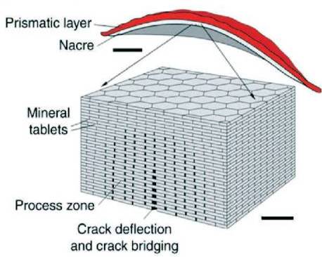
Figure 1. Brick & Mortar Structure of Nacre (Chintapalli, R. et al. 2014)
The purpose of this paper is to explore the use of biomimetic methods in the design of armour systems. It focusses on biological structures found in nature that feature both rigid and flexible armours, analysing their structures and determining which are the most widely successful. A study was conducted on three bio-inspired structures built in Creo Parametric and tested using Finite Element Analysis (FEA) software to determine which structure had the best impact resistance. The study was conducted based on parameters from a study conducted on impact testing biological materials (Lee et al., 2011). The aim of the study was to discover if a bio-inspired model built using ABS (Acrylonitrile Butadiene Styrene) and silicone, based on the structure of an osteoderm would perform well under impact.
Biomimicry is a broad discipline spanning engineering, design, science, and architecture. It is based on the understanding and imitation of biological systems and structures to create improved technologies, materials, and designs to help solve complex human problems. Nature has evolved over millions of years to provide solutions for almost every aspect of life, from water collection, to aerodynamics, to protective armours. In recent years, biomimetic design methods has become a key tool in design to come up with innovative new ways to tackle existing problems.
The focus of this study is on the systems and structures found within natural armours and how these can be replicated using biomimetic design methods. This study will examine how others have used biomimicry to create new designs and systems, specifically focussing on armour and protection. It will also explore the use of additive manufacturing techniques to create and test these new systems and their material properties.
There are many variations on natural armours, ranging from marine animals to land based, all with their own unique characteristics. This study aims to determine which biological armour is the most successful and diverse based on existing studies and papers. Based on this existing research, this paper explores the design of three variations of the same armour structure to find which is best at coping with impact forces.
There are wide ranging potential applications for a successful bio-inspired armour, from protective clothing to defensive structures. There is even wider potential for a successful armour system which is capable of being printed via additive manufacture. Given these constraints, this paper focusses on developing a design which is built using commonly printed materials, and could be made widely available for download.
The aims of the study are:
The objectives of the study are:
In one paper (Vincent et al., 2006), it is stated that because no framework exists on the development of biomimetic structures and materials, it is often very difficult to create a successful prototype. Much of biomimetic design methods relies on the scientific discovery of an unusual characteristic or phenomenon found in nature. A simple replication of this phenomenon is usually unsuccessful and often the biomimetic structures and designs that do succeed hold very little resemblance to the original biological version. Part of the issue found in the study suggests that because “in biomimetic design methods, every time we need to design a new technical system we have to start afresh” (Vincent et al., 2006) it can be difficult to come up with successful biomimetic solutions. The study also suggests that the distinct differences between how biology and engineering develop could be why it is so difficult to fully replicate natural systems. Whereas biology develops through “evolution and natural selection” (Vincent et al., 2006), engineering is the complete opposite, based on the “result of decision-making; it is prescriptive and generates rules and regularities” (Vincent et al., 2006)
The phrase 'graceful failure' is used to describe the load bearing capability of natural materials and structures ( Bond, Richman, and McNaughton, 1995). These natural composites are often seen as being fairly poor and often brittle when isolated, however when built into a natural system can exhibit excellent properties such as strength and toughness.
Barthelat and Espinosa (2007) review the methods used to create and test samples of the nacre layer in shells. In the experiment 'dog bone' shaped pieces are cut from red abalone shell, and tested for its tensile and fracture strength. The study is an interesting experiment overall, and one positive is that the shell was tested in both its hydrated and dry states. The study shows that dry, nacre “behaves like a monolithic ceramic and fails in a brittle fashion” (Barthelat and Espinosa 2007), however in its hydrated state the result is an elastic response.
The experiment can't replicate the natural conditions that the shell would be placed under, so can't give a completely accurate demonstration of how it would react under stress. Equally the choice of the sample shape is unclear, and perhaps the study could have given some consideration to different sample shapes and sizes.
In Salinas, C. and D. Kisailus' study (2013), exploration of the brick and mortar build of the shell examines how each piece interacts with the next and explains the shell's ability to resist damage. The biomimetic replications of this structure are also explored in the paper and determines that none of these have been fully successful. The findings from these studies suggest that humans currently lack the knowledge to recreate the complex biological structure of nacre, and replicate its properties.
In a study on the structure and natural materials of shells (Mayer and Sarikaya, 2002), there were similar results. The study found that it was not only the natural composite materials that could be replicated, but rather the structure and interfaces which were responsible for the strength of the nacre (see Figure 1).
Figure 1. Brick & Mortar Structure of Nacre (Chintapalli, R. et al. 2014)
In a study conducted on the properties of the turtle carapace (Achrai and Wagner, 2013), the structure is described as a 'sandwich' of dense bone around a porous core. The outer surface of the shell is covered by a keratin layer made up of scutes, which are both waterproof, and provide the first level of protection against impact. The study found that the structure consisted of flat sections of bone which gave it a greater stiffness and strength to weight ratio so that it could withstand bending and compression. Similar to the structure of nacre, the keratin is made up of microscopic layers which are able to slide over one another to a certain extent in order to deflect damage. The bony plates are interconnected by unmineralised fibres which act as a barrier to prevent cracks from spreading across multiple plates. The study also found that in order to resist impact damage, the fibres can become “more intimately entangled” (Achrai and Wagner, 2013) which increases “the overall carapace stiffness” (Achrai and Wagner, 2013)
The study also suggested that the turtle's carapace would react differently in both its hydrated and de-hydrated state. The turtle spends the majority of its time in water, so the carapace is exposed to liquids both internally (bodily fluid) and externally. To test this presumption, the study conducted nano indentation tests on samples in hydrated conditions. The study found that when the shell samples were re-hydrated, “softening arises due to the plasticizing effect of water on the organic molecules” (Achrai and Wagner, 2013). This means that the shell would likely become slightly more malleable in the keratinous layers and would probably react differently when placed under stress. Further testing on this area is yet to be conducted.
Studies into flexible armours are less common. There are many variations into the structural qualities of these armours, with differing methods of shock absorption. Three variations of natural segmented armours are explored (Chintapalli et al., 2014). Fish, armadillo, and crocodile skin are all offered as examples of how this system has developed in different ways. An experiment was conducted to create a simplified version by attaching an engraved glass plate to a layer of flexible silicon rubber.
Eight common biological structural design elements have been identified (Naleway et al., 2015). Overlapping, fibrous, helical, gradient, layered, tubular, cellular, suture, and overlapping. The article gives a basic description of biological structures, and offers some examples of identification. The journal has also created simplified versions of the categories which could be used to develop an idealised version of a biological armour.
In a study on armadillo skin (Chen et al., 2011). an analysis of the build-up of layers and their properties was conducted. The results found that the skin is composed of hard mineralised tiles connected by a soft fibrous layer (see Figure 2). This structure is very similar to that of the turtle carapace found in Achrai and Wagner's (2013) study. In the specially designed test, the tiles were found to have a higher tensile strength when tested in a dry state rather than a hydrated one. The mineralised tiles were found to have a tensile strength of roughly 20 MPa, whereas in its hydrated state the tensile strength was found to be closer to 16 MPa. In similar studies (Lee et al., 2011).the opposite was found to be true, where hydrated samples achieved a higher MPa than their dried counterparts. In this case, the way the material was tested is likely to have had an effect on this outcome. Chen et al.'s (2011) shear test was designed to 'punch out' a single tile in the armadillo carapace, whereas in Lee et al.'s (2011) study, they made use of a drop weight test rig.
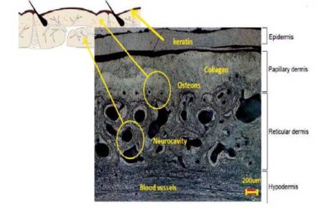
Figure 2. Microscopic Cross Section of the Armadillo's Osteoderm Layer (Chen et al., 2011)
The study (Chen et al. 2011) compares these results to tests conducted on samples of bovine femur and turkey tendon. The comparative Young's modulus of these two materials are higher and lower than that of the armadillo respectively. Bovine femur is considerably higher with a Young's modulus of 19.4 GPa, and turkey tendon comes in at 214 MPa. The armadillo's carapace rates in between these two materials are with a Young's modulus of 425 MPa when dried and 150 MPa when hydrated.
The paper also compares the osteoderm of an armadillo to that of a turtle, finding similar qualities between the structures. Both are made up of bony plates, connected by unmineralised fibres, allowing for a certain degree of flexibility and protection. In another study (Sensale, Jones, and Blanco, 2014), the development of osteoderms is discussed as “ranging from dense calcified tendon to true bone” (Sensale, Jones, and Blanco, 2014). The study cites Moss, stating that osteoderms are not homogeneous, but develop in very different ways both in structure and pattern. The morphology of the osteoderm may be “highly variable in size, shape, articulation, and geometry.” (Sensale, Jones, and Blanco, 2014) according to the study conducted on the energy minimisation principles behind the structure.
The study also refers to osteoderms as being “taxonomically wide-spread” (Sensale, Jones, and Blanco, 2014), due to the wide variety of species that have evolved to develop an osteoderm layer. This is due to the success of the system at “providing protection against mechanical, environmental, and physiological stress” (Sensale, Jones, and Blanco, 2014). The study suggests that the overall structure of the osteoderm features regular hexagonal patterns due to its energy minimisation properties, however finds that there is no direct link to the development of osteoderms in mammals.
Lee et al. (2011) conducted a study on the impact strength of biological materials (see Figure 3). The tested materials are categorised into 'mineralised' and 'keratin based'. In the study, the only flexible material tested is the armadillo carapace. Compared to the other harder materials, its impact strength appears to be fairly low however due to its unique flexible structure it is able to maintain a solid overall structure due to an “ability to localize and arrest damage propagation” (Lee et al., 2011). The carapace fails only on the tile where the impact is localised, with cracks only reaching as far as the edge of the tile. The fibres connecting the bone tiles act as 'damage buffers' (Lee et al., 2011) by bending under the pressure and absorbing the energy from the impact.
The other mineralised materials fail in a brittle manner when put under the same impact pressure. They have a higher failure impact strength, however once each has undergone impact they undergo final failure where the entire structure becomes compromised (Chua, et al., 2014). The keratin based materials comprise a mixture of hydrated and dry material. Hydrated materials did not experience cracking, and instead their state of total failure was at the point where the specimen was fully punctured.
The paper (Lee et al., 2011)also tests the biological samples against synthetic materials, such as plywood and fiberglass. Fiberglass came out as having the highest failure impact strength by a significant margin (see Figure 3). As a composite man-made material its structure is more refined and idealised, whereas natural materials, such as horn and bone can feature deformation and imperfections. The paper concludes that each biological system has “unique hierarchical microstructures” and therefore did not show “uniform impact behavior” (Lee et al., 2011). The paper doesn't take into account the common thicknesses of biological materials however. When tested as 5 mm thick sections some of the biological materials recorded fairly low to average failure impact strengths. However, if the materials were re-tested as whole specimens (e.g. an entire ram horn, or at least the overall structure) then the results may vary. The formation of the material within a larger structure is likely to affect its overall impact strength.
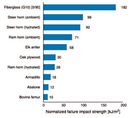
Figure 3. Bar Graph Comparing Failure Impact Strength among the Materials Tested (Lee et al., 2011)
In Yang et al.'s (2012) study of flexible dermal armour, it was found that the size of bone plates compared to the overall size of the animal effects how flexible their armour is. It is stated that “generally, the lower the ratio, the greater the flexibility.” (Yang et al., 2012). The study also states that there are many different types of flexible armour, ranging from fish scales to leatherback turtles. The arrangement of the scales and osteoderms can also affect the properties of a biological armour. Some animals display similar structures of dermal armours, but they hold completely separate functions. For example, the alligators provides protection from attack, but also serves to regulate temperature.
The study examined the structure of the armadillo in detail and found that the hexagonal tiles are “irrigated by blood and stronger than in the dry condition” (Yang et al., 2012). In similar studies, it is also been found that moisture content of a biological material can affect its ability to resist damage. Lee et al., (2011) found that hydrated samples of the same materials performed better than their dry counterparts, exhibiting the “lowest number of different damage modes” (Lee et al., 2011)The biological materials that were heavily dependent on the addition of water to increase their strength had “increased ductility and strain-to-failure” (Lee et al., 2011) when in their hydrated condition. This meant that it took longer and a higher impact strength in order for the materials to experience final failure (complete puncturing or breaking of the sample).
Yang et al., (2012) conclude that flexible dermal armour is not only for protection. The dermal layer serves multiple functions, including temperature and fluid regulation. In the case of bio-inspired armours, these multi-functions are ignored and instead the focus is purely on protection and ability to resist damage. Dermal armours have many similarities across species, such as fish, reptiles, and mammals, but have evolved differently. This is known as 'convergent evolution' (Yang et al., 2012). The study also found that flexible dermal armours have to “compromise between protection and mobility” (Yang et al., 2012).In each case, the biological structure of the armour differs slightly depending on the species and the type of environment they survive in. Different combinations of dermal armour structures result in differing abilities to resist damage and provide flexibility. As stated in the study, leatherback turtles display similar characteristics to other osteoderms, however their flexibility is significantly lower. Equally, fish species have developed very flexible dermal layers that provide more limited protection.
In Sun and Chen's (2013) study on alligator osteoderm, they found that one of the structural elements which gives alligator skin such a high impact resistance is a layer of porous bony plating. Similarly to Achrai and Wagner (2013), they describe the overall structure as a 'sandwich' with a porous layer in between two denser layers of bone. The pores within the osteoderm allow it to experience compression and absorb impact energy without immediate cracking. This structure is also lightweight, and when combined with non-mineralised connective fibres, allows the osteoderm layer to remain flexible. This flexibility is able to “dissipate energy under small loads” (Sun and Chen, 2013) while “deformations of the cellular foam interior absorb impact energy” (Sun and Chen, 2013). In the study, samples of alligator osteoderm were cut and tested in both their dry and re-hydrated conditions. The study found that the samples performed better and exhibited a higher compressive strength when dry, contradicting similar studies on other biological materials, such as Barthelat and Espinosa's (2007) study on nacre, and Lee et al.'s (2011) study on impact resistance.
In Johnson, Bingham, and Wimpenny's (2013) paper they built and tested additive manufactured textiles for their stab resistance. In the study, they print materials which replicate natural systems using layers of scales at varying thicknesses. The study found that the minimum thickness of the material could be printed at in order to meet the testing standards 8.0 mm thickness using PA 2200. The use of a scale system allows the textile to be flexible whilst still achieving the required stab resistance. When the textiles failed, they displayed similar characteristics to an osteoderm layer. A single scale in the pattern would fracture, leaving the rest intact. This is similar to Lee et al.'s (2011) finding where a single bone plate in the armadillo's carapace failed on impact, but left the overall structure whole.
Based on the research conducted and the existing base of knowledge, the next step of this study was to select a biological armour system to focus on. Shell-based armours such as nacre can be excluded as the results from studies show their behaviour is different when submerged and when dried (resulting in a less effective armour) and doesn't allow for any flexibility of movement. The practical applications of rigid armours are far fewer than flexible variants. Equally rigid biological armours tend to be much denser in their structure, resulting in heavier and less mobile materials.
Osteoderms have a wide range of success within nature as a biological armour. The structure is similar across many species, and can be found in a wide range of environments. As mentioned in Yang et al.'s (2012) study this is due to 'convergent evolution'. Each system has adapted differently based on the environment it is found in, and the types of predators and dangers the animals face.
Osteoderm carapaces could be seen as having a wide global success due to the many environments and animals that have evolved with them. Because it can be found in so many different structures, it is an interesting armour to attempt to replicate in 3D CAD software. No studies were found where this had been attempted, although many products refer to their structures as 'armadillo skin'. More often than not, this refers to a purely cosmetic appearance and the actual structures have no similarity to that of the armadillo carapace. In a recent study on the structure of armadillo skin, it was described as “a sandwich composite structure… having relatively denser exterior bony layers and an interior bony network of foam” (Rhee, Horstemeyer, and Ramsay, 2011)The key to developing a successful 3D CAD bio-inspired version of this is to try and replicate these layer structures within the model.
The initial phase of the study was to design a set of CAD models inspired by the structure and systems of osteoderms found in nature. The models take an idealised approach to the structure of an osteoderm (see Figure 4), with sections to replicate the hard exterior plates and their interconnecting fibres. The aim was to create a flexible armour system that gives a good level of impact resistance and has the potential for further development for use in product applications.
Because the three models are idealised and are simpler structures than a natural osteoderm, the keratin layer was not be built in as a feature. Keratin makes up one layer of skin, and because the models will be built in plastics, it is unnecessary to try and replicate this layer. It doesn't necessarily affect the mechanical properties of the armour to remove the keratin, so it was deemed an unnecessary addition to the bio-inspired material designs.
The three designs (see Figure 5) are made up in their basic forms of solid, flexible, and void (empty) sections. These mimic the bone plates, the fibres, and the osteons, respectively within the biological structure. It was important to include these three features in the designs as they are key to the success of the biological armour. The fibres allow the structure to be flexible, whereas the solid sections give it strength and rigidity. The void sections are able to absorb some of the energy from an impact and dissipate its effect. The hexagonal columns taper as they reach the base which allows the material to flex in one direction when pressure is applied on either end.
Three models were designed and tested, showing different iterations of structures to find which is the most successful. The designs were built using PTC Creo Parametric and tested using the FEA package in Creo to simulate the models under pressure. This resulted in three data sets showing the rate of success of each model. The models were built up in different configurations of flexible material and solid to represent the bone matter and Sharpey's fibres found in the structure of an osteoderm layer (see Figure 4). The solid bone was represented with hexagonal tapering columns which mimic the scales found in the front and rear of an armadillo's carapace. The columns are connected by a solid layer of flexible rubberised plastic to represent the fibres connecting the plates.
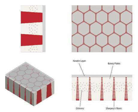
Figure 4. Simplified Structure of an Osteoderm
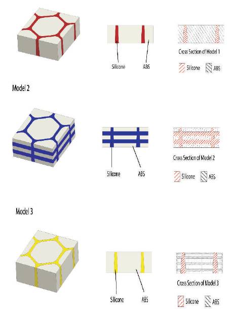
Figure 5. Diagram Showing the Structure of the Three Models that were Built and Tested using Creo Parametric
Figure 5 shows the three designs, displaying their structure both externally and internally. Model 1 is made up of solid ABS shown in the beige sections, with the darkly marked sections showing solid silicone. Model 2 is built up in layers of solid ABS (beige) sandwiched in between layers of solid silicone. Model 3 is built of hollow columns of ABS with thin shelves bridging the interior and void sections in between. Whereas Models 1 and 2 are built to withstand impact and spread the damage, Model 1 has been designed to fail to a certain extent. The theory behind the structure is that the outer shell of ABS would fracture under impact, but the force would be lessened as it enters the void spaces underneath. The interior layers of ABS may also fracture to a certain degree, but should help the model retain its overall shape.
The models were built to the same specifications set for the sample sizes that were used and tested in Lee et al.'s (2011) paper. Each sample was created at a size of 20 mm x 20 mm by 5 mm thick. The thickness of the models was increased slightly from the biological samples used in order to allow for more flexibility when it came to modelling them in the CAD software.
The properties of silicone and ABS were used to test the models and applied to the flexible and rigid sections, respectively. Silicone was chosen for its ability to bend and flex and still return to its original shape, as well as being a very common rubber material. ABS was chosen for the rigid sections as it demonstrates good strength, rigidity, and hardness. It is also commonly used in rapid prototyping which would easily allow for the models to be printed and physically tested in future studies. The two parameters required to simulate materials in FEA is Poisson's ratio and Young's modulus. The values used for each material are as follows:
For Silicone, the Poisson's Ratio is 0.38 and Young's modulus is 1.7 GPa. For ABS, the Poisson's Ratio is 0.47 and Young's modulus is 0.05 GPa.
The results from the FEA testing were used to draw a comparison between the artificial bio-inspired models and the actual biological systems in place in osteoderms. The data for this part of the experiment was sourced from papers and journals that have conducted tests on osteoderm carapaces as well as other biological materials, such as horn and bone. Because of the use of FEA rather than physical testing, there was a reduced risk of human error affecting the results. It also ensured that the test each model was subjected to was identical, and the results should be an accurate representation of the impact simulation.
Each of the models were constrained in the same way, stopping movement in all directions to replicate the equipment set up in Lee et al.'s (2011) study. The cover plate aperture used in the experiment measures 12.69 mm. Each of the plates in the models were created at 12.82 mm to replicate roughly the same surface size to apply the impact force to.
In Lee et al.'s (2011) study the following equation was used
to determine the energy of the impact on the samples:
 E = mgh
In this case, E is the impact energy, m is the mass of the
impactor, g is the gravitational constant, and h is the height
that the impactor was dropped from. In the FEA program
the same equation was used to determine the impact,
using the same constants from Lee et al.'s (2011) study. This
was to ensure that the results from the FEA testing could be
used to draw a comparison with the existing results. In this
case, m was 1.2 kg, h was 0.74 m, and g was 9.81 m/s²,
therefore:
E = 1.2 x 9.81 x 0.74
= 8.71 J
This means that the maximum impact energy is 8.7 Joules and the maximum velocity of the impactor is 3.8 m/s.
Creo's FEA testing doesn't have a specific option to create
an impact test, so instead of using the impact energy
found above, a different equation was used to get an
estimate for the force of the falling impactor. The
parameters from Lee et al.'s (2011) study were put into the
following calculations to find the force of the impact;
Initial Potential Energy (PE) = Final Kinetic Energy (KE)
At the point of rest before the object has begun to fall;
PE = mgh
KE = 0
Kinetic energy at the start of the object's fall is equal to zero,
as the object is falling from rest.
At the point of impact;
PE = 0
KE = 1/2(mv²)
Therefore; mgh = 1/2(mv²)
The equation to find the impact force is;
F = (1/2(mv²))/d
where,
Height (m) = 0.74
Mass (kg) = 1.2
Gravity (m/s²) = 9.8
Distance travelled after impact (m) = 0.05
The distance travelled after impact was set to 0.05 m because this is the maximum distance the impactor could travel if complete penetration of the sample occurred.
Each sample stands at 5 mm thick, and sits on a solid surface which would prevent the impactor travelling any further.
Velocity (m/s) =3.81
Kinetic Energy (J) = 8.7
Impact Force (N) =174.05
The final impact force of 174 Newtons was used in the FEA testing and exerted on the top face of each model.
The images shown in Figure 6 are screen captures showing the stress (MPa) exerted on each part of the models.

Figure 6. Screenshots of the FEA Results for each Model in Different Elevations of Stress Rates Tested in Creo Parametric Model (1a) Stress Concentration in Top Face of Test Component Model (1b) Stress Distribution in Bottom Face of Test Component Model (1c) Stress Distribution in Bottom Face of Test Component Model (2a) Stress Concentration in Top Face of Test Component Model (2b) Stress Concentration in Bottom Face of Test Component Model (2c) Stress Concentration in Sectional View of Test Component Model (3a) Stress Concentration in Top View of Test Component Model (3b) Stress Concentration in Bottom View of Test Component Model (3c) Stress Concentration in Sectional View of Test Component Model (3d) Section View 2
The images shown in Figure 6 are taken directly from the FEA testing results window and have not been modified in any other way. For each model there is an image of the top surface, the bottom surface, and a sectional view to show the stress experienced internally in each model across the same plane. For Model 3 two sectional views have been shown to highlight the area which experienced the highest stress rate. This was inside the main structure of the model, and needed to be shown from a low angle, hence the inclusion of the 4th image.
Model 1a shows stress concentration in Top Face of test component illustrating a uniform distribution in the medium range of stress rate. Model 1b shows stress distribution in Bottom Face of test component illustrating a localized distribution in the medium-to-high range of stress rate. Model 1c shows stress distribution in Top face sectional view of test component illustrating a localized distribution in the medium range of stress rate. Model 2a shows stress concentration in Top Face of test component illustrating a uniform distribution in the medium range of stress rate. Model 2b shows stress concentration in Bottom Face of test component illustrating a uniform distribution in the low range of stress rate. Model 2c shows stress concentration in Top Face sectional view of test component illustrating a uniform distribution in the medium range of stress rate. Model 3a shows stress concentration in Top Face of test component illustrating a uniform distribution in the low-tomedium range of stress rate. Model 3b shows stress concentration in Bottom Face of test component illustrating a uniform distribution in the very low range of stress rate. Model 3c shows stress concentration in Bottom Face sectional view of test component illustrating a uniform distribution in the low range of stress rate. Model 3d shows the Section View 2 illustrating layered sections of test component illustrating medium stress concentrations in top face and low on the bottom.
Table 1 shows each model alongside the maximum and minimum recording of stress experienced, measured in MPa. In the FEA software, the results are expressed via a 3D model which is coloured to show the areas that experienced the highest stresses, and the lowest.
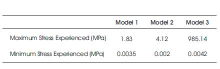
Table 1. Comparison of Maximum and Minimum Stress for Each Model
For the purposes of this study and the FEA testing analysis, the tensile strength of ABS and silicone will be used as the measure of whether the models survived the impact. If the highest recorded stress is more than the tensile strength of either material, then it will be assumed that testing the models physically would have resulted in total failure. This means cracking or fracture in the model, damaging its overall structure. The tensile strength of ABS is 42.5 - 44.8 MPa (teststandard.com, 2016), with an average tensile strength of 44 MPa. The tensile strength of Silicone is between 2.4 and 5.5 MPa. These tensile strengths were found from material standards sheets available online.
The model which experienced the lowest level of stress was Model 1. Its highest stress point was 1.83 MPa, which was exerted on the bottom face around the edges of the central ABS plate. Model 1 is built up of solid ABS columns with interconnecting silicone holding the structure. When placed under the impact force, the structure held up quite well, with moderate stress (1.0 - 1.2 MPa) experienced on the top surface of the plate, and the majority of the silicone experiencing very low stress at only 0.0035 MPa. Based on these figures, it can be assumed that if Model 1 was printed and tested physically using the same apparatus as in Lee et al.'s (2011) paper, it would have showed a reasonable impact strength. Based on the tensile strength of ABS, the material would have survived the impact without experiencing total failure (e.g. fracture, puncture, etc.,) because the overall maximum stress experienced was less than 42.5 MPa.
The same can be said of Model 2 which experienced a maximum stress of 4.12 MPa and a minimum of 0.002 MPa. This meant that although the ABS plates experienced moderate stress, the silicone sections were able to help dissipate the effect of the impact and absorb some of the energy from it. The fact that Model 2 had a lower minimum stress than model 1 suggests that it was able to more effectively dissipate the effect of the impact. The structure of Model 2 is layering of ABS plates and silicone. The addition of the silicone layers seems to have helped the overall structure to cope with the impact better. As with Model 1, the tensile strength of ABS is much higher than the highest recorded stress, so it can be assumed that the model survived without experiencing total failure.
Model 3 experienced the highest maximum stress by far. The FEA test recorded 985 MPa on the uppermost ABS plate, around the edges of the underside face. This is far larger than the tensile strength of ABS which means that the plate would have suffered complete fracture in a real life scenario. Because of the nature of FEA, the physical damage from an impact cannot be displayed so it is hard to assess how severe the damage from the impact would have been. Considering that the top plate of ABS would have fractured, it is likely that the internal plates would also have suffered stress from the impact, and potentially experienced fracture as well. The model would have been classified as having experienced total failure after the plate was fully punctured.
It is possible that the figure recorded for Model 3 could also be an anomaly. Considering that it recorded a stress rate so much higher than the other two models could suggest that there was an error in the experiment. This could have been made during setup of the FEA testing, or during the construction of the CAD model. The force placed on each model was 174 Newtons, which means that the error could have been made in constraining the model, or in the making and assigning of materials. A good way to test whether or not this figure is an anomaly would be to subject the models to the same FEA testing again, as well as trying the same scenario, but applying different forces. Testing each model with a force lower than 174 Newtons and a force which was higher would show whether Model 3 would react in the same way to a variety of forces. If this was the case, then it could be assumed that the recorded stress for Model 3 was accurate.
In all cases, the silicone sections of each model experienced minimal stress upon impact. This could be because the sight of the impact was directly on the top face of the central ABS plate, and did not directly affect the silicone. In Model 2, even the silicone layers which lie directly beneath the top ABS plate only experienced minimal stress. This could be due to a fault in the FEA testing where the materials haven't acted exactly as they would in reality. It could also be that the energy from the impact transferred through the silicone down to the second ABS plate without really affecting the silicone itself. It is likely that the high elasticity of the material allowed it to cope with the impact with only minimal stress.
From the results, it is clear than using silicone, or any other variety of flexible rubber, is the key in the success of the models. The models which performed the best (Model 1 and 2) had solid sections of both ABS and silicone. It would be useful for further testing to try and place the sight of the impact onto a section of the silicone to see how it copes when faced with direct force. Depending on the results, it may show that slight alterations to the structure of the models could be made to improve their tensile strength. For example, if the silicone failed under the impact, the ABS plates could be raised slightly above the top surface of the silicone to ensure that it never experienced direct impact.
Using Creo Parametric to create the models did have some limitations. It is difficult to simulate biological structures in the program. The models created were limited to being quite regimented in dimension and structure. This affected the overall design and build of the models, and resulted in very simple structures when compared to biological forms. It is likely that this did have quite a large effect on the outcome of the results. For example, the ability to build in randomly generated structures such as pores into the model's ABS sections could have had an effect on the ability of the model to absorb impact. Other CAD programs are more suited to creating these styles of model, such as Rhinoceros 3D and its plug-in; Grasshopper 3D.
Another limitation is using the results from Lee et al.'s (2011) paper to compare the CAD model FEA results. Using a physical test and its results to compare against FEA does have some issues associated with it. The samples used in testing the biological materials would have been in a very different environment to the one simulated in FEA. FEA creates an idealised version of a test where the sample isn't affected by any external factors, such as temperature or humidity. The results taken from the FEA testing are also quite difficult to draw direct comparisons to. It is unclear how the simulated models reacted against the biological samples tested, so a direct comparison is not possible.
In Lee et al.'s (2011) paper they also use the appearance of internal and external damage to determine the sample's failure points. For example, a 'dimple' in the surface of the sample is marked as the first sign of damage, with cracking or puncture of the specimen marking its failure point. Using FEA doesn't allow for this same level of comparison. The program allows you to view the amount of stress placed on certain areas of the model, but without a physical version to test using the same apparatus, it is difficult to use this as a comparison. Model 3 is a good example of where physical testing would prove far more insight. It is very unclear based on just the FEA what would happen to Model 3 under the given force of impact. It is likely that the top ABS plate would collapse, but after this it is difficult to determine the extent of the damage done. It could be that through physical testing, Model 3 would have been able to cope with the impact through localised failure. The model was designed to collapse under impact, but to dissipate the effect of the impact as it travelled through the material by incorporating a mixture of solid ABS plates and void sections. The structure probably would have still remained intact overall, with only one damaged plate. Similarly, the other two models appeared to cope better with the impact, but in reality the models may have suffered more damage to their overall structure.
Model 1 shows that the base of the ABS plate was still experiencing moderate stress at roughly 1 MPa. In a physical scenario, whatever lies underneath the material would also have experienced stress from the impact and the energy would have been transferred through the ABS directly into it. If for example Model 1 was a small section of a much larger body armour, the person wearing the armour would still have felt the impact and experienced moderate stress to their skin. Whereas Model 3 shows the lowest stress recording out of the three on its bottom face. This could mean that in a practical situation, Model 3 may provide better protection overall for its ability to completely reduce the impact energy before it has travelled through the whole model.
One improvement which could be made to the experiment conducted using FEA is the use of an impact tool head to apply the force to the models rather than applying it a whole tile. In Lee et al.'s (2011) experiment, the impactor tip diameter was 3.2 mm. This means that the entire force would have been applied to a much smaller area of the tile, rather than being spread across the whole face. The use of FEA limited this to a degree, but it is something which could be altered for future testing to improve the reliability and accuracy of the results.
Another area that could be looked into is testing different materials in the models and seeing how they compare against the results from the silicone and ABS mix. It could be that there are other rubber materials which are better at absorbing impact energy, or that there are plastics which are better suited to coping with impact. Testing other materials which are commonly used in additive manufacture would be an interesting comparison. This would show whether there are any common AM materials which would allow you to create simple but efficient impact resistant material.
Equally testing out even more configurations of flexible, solid, and void sections could provide a better solution with a higher impact resistance than the models. Trying the same configurations but with more layering, or testing different thicknesses of material layers would also have an effect on this. The current models tested were just three options on how these parts could be configured, with hundreds more left untested.
The use of a different 3D CAD program to create the models could be another angle to take further. Creo Parametric is somewhat restricted on the types of forms and models that can be created, whereas other programs lend themselves better to the creation of more randomised/natural patterns and sequences. As mentioned previously, Grasshopper 3D could provide a better tool for creating the bio-inspired models and would allow a great degree of freedom when it came to the form, and the inclusion of specific characteristics. For example in real bone, porous holes tend to form in layers within the structure. These are also commonly found in other biological structures such as horn and antlers where impact resistance and strength are key. Creating a 3D CAD model that featured a randomised pattern of holes could be an interesting test to see how they affect the overall strength of the structure.
After conducting FEA testing on the three bio-inspired models, it is clear that the only way to get a better understanding of how well the structures performed under impact would be to test them physically. From the FEA results it seems that Model 1 had the best overall performance and ability to resist impact damage, however the accuracy of the results is questionable. Materials and structures in FEA don not necessarily behave like they would in their physical form. Using the same parameters as in Lee et al.'s (2011) study, the models could be physically tested and the results could be more accurately compared to the existing data recorded from biological materials. Given this information, the models could be properly assessed and improved based on the results.
One suggestion for future testing is to create rapid prototyped versions of each design and test it as a physical model. This would allow for further experimentation, allowing the structure to be subjected to various conditions and habitats. Testing the materials in both wet and dry conditions, for example, could reveal whether it would be applicable for outdoor use or whether adverse weather would affect the material's overall performance. This would also allow for a more in-depth analysis and comparisons drawn between this study and existing papers such as in Barthelat and Espinosa (2007) where the hydrated state of nacre was found to have a profound effect on its elastic response.
Testing different types of solid and flexible materials, and different combinations of materials would also be a good way to test the physical properties of the models. Certain materials may create a better overall system and help improve the structure's mechanical properties. Other materials commonly used in additive manufacture would provide a helpful comparison point for others wishing to explore the potential behind bio-inspired 3D printed products. Specifically armour systems where the availability, cost, weight, and flexibility of the materials all affect its overall success.
Testing physical models alongside pieces of osteoderm carapace would also prove to be a better comparison than using pre-existing results and comparing them to the FEA generated results. This would allow for a more accurate and controlled experiment, where all materials were tested under exactly the same environment and subjected to the same equipment.
Another way to continue this line of research would be to create more CAD versions of the model in different configurations and test if there is a better overall structure.
Changing the thickness of the model as well could be another angle to take, to see whether this affects the results of the impact testing, and if so by how much. This structural design would be best suited for use in protective clothing and armours, so it would be beneficial to create the thinnest and lightest design possible. Another suggestion is to test different sizes of the structure, creating varying sizes of the hexagonal formations to see its effect on the results of the experiment.