(1)
Oil is primarily used for lubricating compressors in a Refrigeration system. This results in an Oil-refrigerant mixture being formed which has poor heat transfer capacity and comparatively higher pressure drop. Oil separators are used to remove and filter out this oil from the mixture to improve the performance of the system. This oil is otherwise disposed off, resulting in severe economic and environmental hazards. The main objective of the present work is to design a compact and highly efficient Oil separator for Ammonia Refrigeration System. Various alternative designs of an Oil separator have been proposed. Weight, cost, strength, durability, and effectiveness of each design were considered independently, and a final decision to implement Vertical Demister type Oil Separator has been suggested. Even a small increase in separation efficiency would lead to considerable cost and energy savings.
Lubrication is essential to keep friction and wear to minimum levels. The life of the compressor and its reliability heavily depends upon the quality of lubrication system. There are standard recommendations for the amount of lubricating oil to be provided depending upon the number of operating hours and capacity of the compressor. This oil has to be separated from the refrigerant. Otherwise, it may lead to severe issues like accumulation of oil in the evaporator, higher pressure drop, reduction in heat transfer capacity and consequently, a lesser coefficient of performance in Vapour Compression Refrigeration Systems [8]. The type of oil separator traditionally found in the discharge line of reciprocating compressor is a small vessel that uses abrupt changes of direction of the oilladen refrigerant or filter elements to separate oil droplets that then periodically are returned to the compressor crankcase. The oil concentration leaving this type of separator is in the range of 50 to 80 ppm. When oil-injected screw compressors appeared, they required a much more efficient separator, so the coalescing type of oil separator was developed. This reduces the oil concentration to approximately 5 ppm. The most popular systems used for Reciprocating Compressors are the Baffle Type Oil Separators and Demister Pad Type Oil Separators.
Brunazzi [2] represented a mechanistic model after comparing experimental results on various commercial wire mesh mist eliminators.
Burkholz [3] conducted systematic experimental study on wire mesh mist eliminators. His analysis was primarily limited only to perfectly square meshes perpendicular to the direction of flow.
Feng et al., [4] have conducted experimental and computational simulations to validate their model for analysing trajectories of oil droplets with varying droplet sizes and for varying residence times.
Slettebø, E. S. [9] explores various aspects of bubble dynamics and separation systems used to remove gases from liquids. Parameters, such as separator size, fluid properties have been modelled to develop models to represent the physical processes involved.
Uki, T., et al. [10] has laid more emphasis on use of vortex breaker and centrifugal effect for gas-liquid separators used in process Industries.
The design for oil separator can be divided into two major components: Pressure Vessel Design and Filter Design. Standard results along with ASME (American Standard for Mechanical Engineering) codes have been utilised in obtaining optimum feasible solution.
A Market survey was conducted across Engineering Vendors to compare the relative strengths and costs associated with the most common engineering materials.
Material selection is usually an intuitive process based on past experiences, a standard material is usually chosen blindly.
A small step has been taken forward to understand the economics behind the Material Selection along with its Engineering aspects. 40 Engineering Materials were studied as a part of the survey.
Following assumptions were made for the analysis of the system.
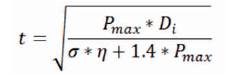
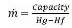
Thickness of Pressure Vessel (t) and Mass flow rate (m) were calculated using equations (1) and (2) respectively. The values for Enthalpy change (Hg-Hf) was obtained using standard refrigerant charts.
The pressure vessel head was optimised with respect to cost of manufacturing and weight of the vessel using a MATLAB code.
Semi-Ellipsoidal, Torispherical, and Hemispherical Heads were compared using this code.
Vessel sizing is another important aspect that has been considered in the design of oil separator. Height (H) available for separation is the most important parameter affecting residence time. The graph of Disengaging Height vs Vessel Diameter is shown in Figure 1.
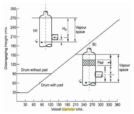
Figure 1. Graph of Disengaging Height vs. Vessel Diameter [6]
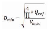
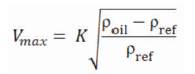
The minimum vessel diameter (Dmin) would be obtained for maximum separation velocity (Vmax) as shown in equation (3).
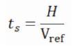
Residence time (ts) for the oil droplets to settle down beneath the separator vessel was determined for various multi-cylinder arrangements using equation (4).
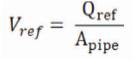
The velocity at which Refrigerant (Vref) flows in the system is ref given by equation (5). The maximum velocity (Vmax) for separation is limited by equation (6). The densities of Oil (ρoil) and Ammonia (ρref) were taken from standard charts.
ATLAS software was used to obtain the numerical results for separation efficiency from the demister pad. Standard normal distribution for oil droplet size with mean of one micron was used.
The intrinsic relationship between pitch and porosity was investigated using a MATLAB code.
From the Material cost survey, it is clearly seen that Steel is the best engineering material with respect to strength to cost ratio. Steel has a strength to cost ratio of over 10 as shown in Table 1.
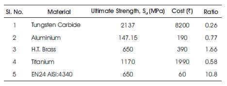
Table 1. Material Cost-Strength Survey [7]
The material and manufacturing costs were taken together to understand the most economical head for the pressure vessel. Considering weight and cost constraints, Semi- Ellipsoidal (2:1) would be the optimum shape for a compact and lightweight oil separator. Cost Optimisation for Head of Pressure Vessel is shown in Table 2.
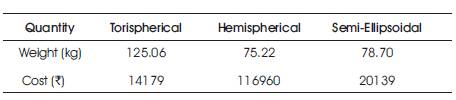
Table 2. Cost Optimisation for Head of Pressure Vessel [1]
The thickness of the pressure vessel was safely taken as 10 mm. Exact design calculations show that, thickness of 7 mm is sufficient for 22 bar design pressure as shown in Table 3.
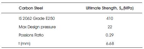
Table 3. Thickness of Pressure Vessel
The entire Oil separator assembly was modelled in CATIA V5 using 80 mm diameter for inlet and outlet pipes as shown in Figure 2.
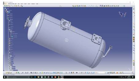
Figure 2. CATIA Model for Oil Separator
Pressure drop is almost negligible as calculated in Table 4. The velocity obtained inside the demister was found to be within permissible limits as shown in Table 5.
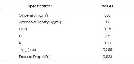
Table 4. Pressure Drop and Maximum Velocity for Separation through Demister [5]
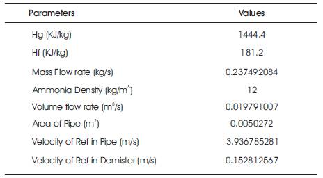
Table 5. Mass Flow Rate of Refrigerant
The extremely low pressure drop makes demister pads a very attractive choice for separation devices. The results show that a 150 mm Demister pad has a pressure drop of less than 1 KPa.
Residence time calculated for various configurations has been summarised in Table 6. Higher residence time would ensure more efficient oil droplet separation. Separation Height (H) available inside the vessel has been assumed using empirical relations.
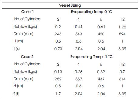
Table 6. Vessel Sizing
ATLAS software was used to find the droplet size for different values of separation efficiency. Table 7 shows the final result of numerical analysis.

Table 7. Atlas Software Results
The plot of Droplet size against Separation efficiency has been shown in Figure 3. It shows that all droplet sizes above 1.2 microns would be filtered by the demister pad under consideration.
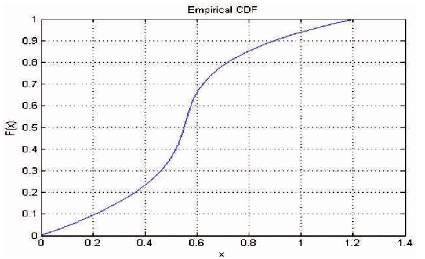
Figure 3. Droplet Size vs. Separation Efficiency
Table 8 gives us the relationship between porosity of the demister and the pitch between the wires of the two consecutive meshes. Plot of the results presented in Table 8 are shown in Figure 4.
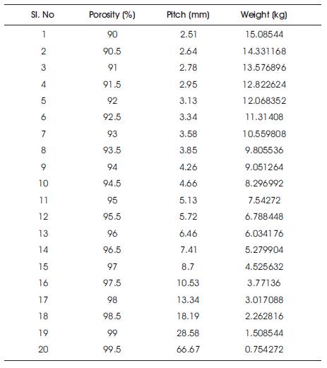
Table 8. Porosity vs. Pitch
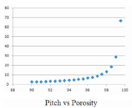
Figure 4. Plot of the Results in Table 8
From the standard recommendations for a wire mesh demister pad, we could conclude that a 5 mm pitch along with 95% porosity would be ideal for the given demister pad with 150 mm thickness.
The proposed design having an increased efficiency of 95% would result in enormous savings in terms of carbon emissions over the existing component with an efficiency of 90%.
The results have shown that for higher capacity multi-cylinder arrangements, the savings is even more significant as represented in Table 9.
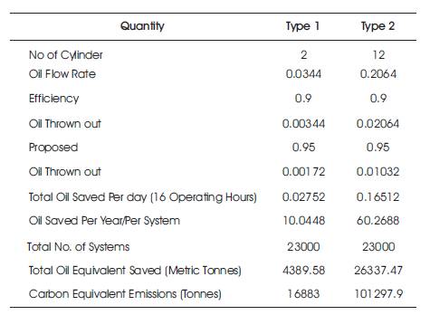
Table 9. Environmental Impact of Improved Design
Demister pads are a viable alternative to conventional cyclonic separation and Vane type separation devices which have higher cost and higher pressure drop.
Semi-Ellipsoidal Head for the pressure vessel have been chosen from cost and weight perspective.
Separation efficiency curves obtained show the variation of separation efficiency with respect to oil droplet size. Extensive experimentation would have to be performed to determine the critical parameters accurately.
Even small improvements in separation efficiency could result in substantial gains in terms of environmental impact.