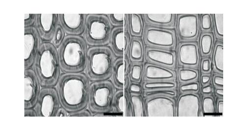
Figure 1. (Ruelle, 2014): A Comparison of the Cell Wall Structure of Reaction Wood found in Pinus Pilaster, alongside Wood from a Non-reaction Wood Sample from the Same Specimen. 20 μm scale bar
All known species of tree are capable of adapting to the dynamic changes in load encountered in their environment. This is achieved through the growth of reaction wood, which differs considerably in microstructure from ordinary timber, and has many unique properties. However, the presence of reaction wood is considered to be detrimental for most industrial purposes due to its unpredictable nature. This study aims to compare the microstructure of reaction wood with that of ordinary wood fibres in order to discern which configuration is mechanically superior. Samples were idealised and modelled using Computer Aided Design software, and Finite Element Analysis (FEA) was used to assess the performance of each respective microstructure. The results of the analysis showed that the reaction wood sample was deformed by 23% less during a cantilever beam test than the standard wood sample, and experienced significantly less Von Mises stress throughout its structure. However, it was concluded that these results were not representative of reaction wood samples across all species, and were lacking in reliability due to the restricted sample size and limited calibration data available.
Trees are one of nature's most fascinating and impressive organisms, growing to heights unparalleled by any other life form on earth and remaining prolific even in some of the most challenging environments. Trees growing in harsh environments are able to thrive even on steep gradients and when subjected to relentless high winds, managing to resist this constant assault and orientate themselves skywards. These complex biological structures are able to withstand dynamic changes in load through growth optimisation strategies. This report will investigate the natural phenomena of thigmomorphogenesis; the adaptive growth of reaction wood due to external mechanical stimuli (Jaffe, 1973), and gravitropism; the adaptive growth of material in response to gravity (Chen et al., 1999). Reaction wood is the term used to describe the material added by trees along areas which are exposed to additional load or stress from external factors, typically at the bases of branches or around wounds. This material has very different mechanical properties to those of standard timber samples due to its composition and unique cellular structure.
These differences in internal structure pose problems when processing timber containing reaction wood, as timber with a heterogeneous composition can be unpredictable under load and during tooling. However, if the structural composition of reaction wood yields significant benefits in mechanical performance over typical wood samples, this could yield many useful applications both in safety, cost and sustainability. If thigmomorphogenesis could be harnessed and induced artificially to create a homogenous piece of timber composed entirely of reaction wood, it could be possible that fast-growing sustainable softwood species such as pine could replace slow-growing, expensive hardwoods in a range of applications.
The primary questions this research project seeks to answer are:
The objectives of this research are:
Reaction wood grows in two different varieties, compression wood in gymnosperms (seed bearing plants) and tension wood in angiosperms (flowering plants). All species of tree studied have been shown to have the ability to orientate themselves to better cope with external stresses through the growth of reaction wood, a process driven by variations in cambial activity (Sinnott EW, 1952). There has been extensive research into the hormonal factors which result in the production of reaction wood, but a definite conclusion has not yet been reached (Pilate et al., 2004). It has been identified that the distribution of the hormone Auxin could have a major part to play in the formation of reaction wood. Auxin has been found to accumulate on the lower sides of limbs that have been bent or tilted, prompting accelerated growth in these areas to resume vertical growth (Cholodny N., 1926). In addition to this, the lack of auxin in the upper part of the limb was shown in Leach and Wareing's research to decelerate growth in that region, resulting in formation of tension wood, which acts to pull the limb upwards. The combination of these two mechanisms assists the organism in reclaiming a vertical growth pattern (Leach & Wareing, 1967). There is also some evidence that the volatile hormone Ethylene is a contributing factor to reaction wood formation. It is described as being partially responsible for many plant functions, particularly in response to gravity. Ethylene production can be stimulated locally by tilting, shaking and bending, as well as other physical stresses (Abeles et al., 1992, Wani & Khan 2011).
At a macroscopic level, reaction wood can be difficult to identify, even to the experienced eye of a professional woodworker (Doğu & Grabner, 2010). Many methods can be employed to identify reaction wood, albeit with varying degrees of accuracy. There are some aesthetic differences associated with the presence of reaction wood. Freshly cut sections of timber may exhibit a shiny finish across areas of tension wood (Ruelle, 2014). These areas can also appear darker than their surrounding wood, tending towards a dark brown colouration, particularly when sourced from tropical trees (Ruelle, 2014, Bozkurt and Erdin, 2000). Staining samples with Zinc-chlorine-iodide, which is known as Herzberg reagent, can help to identify the presence and distinguish between the varying severities of reaction wood. This is a very effective technique when used on samples from Beech and Poplar species. However, despite being the most commonly used method of identification, this method is not universal, and gives inaccurate readings when Oak and other hardwoods are used (Doğu & Grabner, 2010). A staining method has yet to be developed which is applicable to all species. Reaction wood can also be identified macroscopically by measuring growth stress index, longitudinal and tangential shrinkage, by evaluating density as well as through ultrasounds, X-rays, and Nuclear Magnetic Resonance (NMR) techniques (ibid).
There are distinct characteristics found in samples of reaction wood at a cellular level which are responsible for its differing mechanical properties, summarised in this quote from Julien Ruelle;
“If we look at the tissue organisation we see that in compression wood it is largely the tracheids that display a different anatomy, whereas the other tissues of the wood structure appear to be less affected.” - (Ruelle, 2014)
Ruelle's research found the tracheid cells in compression wood to be rounded in structure (Figure 1, left), and are configured with many voids and gaps in the intercellular space. A sample of normal wood structure (Figure 1, right) showed a much more regular structure with a tendency to have tracheid cells of rectangular or other regular shapes, with little to no intercellular gaps. In terms of composition, compression wood is also found to have more lignin than normal wood, and exhibits a proportional reduction in cellulose (Wani & Khan, 2011). Tension wood is found to have even more extensive variations in its structure. Whilst its cell walls seem to be equivalently lignified to those of the surrounding wood, there is evidence of a gelatinous layer within each cell comprised almost entirely of cellulose. This layer is so thick that it can often fill the majority of the lumen (Dejardin et al., 2010).
Figure 1. (Ruelle, 2014): A Comparison of the Cell Wall Structure of Reaction Wood found in Pinus Pilaster, alongside Wood from a Non-reaction Wood Sample from the Same Specimen. 20 μm scale bar
There has been conflicting research into the mechanical performance of reaction wood. Reaction woods have been attributed with having some desirable properties.
Compression wood is described as having increased resistance to shear stress when compared against ordinary wood (Wimmer & Johansson, 2014), as well as higher axial crushing strength (Clair & Thibaut, 2014). There is also evidence that when correctly processed, compression wood can achieve a superior quality of surface finish, as well as having a lower percentage of water uptake after drying, as well as the swelling that this causes (ibid.). Studies have also shown that compression wood has excellent resistance to degradation from fungi (ibid.). Tension wood is attributed with increased toughness and impact resistance over non-reaction wood of the same species (ibid). However, this is contradicted by earlier research, which showed compression wood to be lower in “practically all strength properties as compared to normal wood” (Pillow & Luxford, 1937). As this area of investigation is rife with contradiction, the results of any testing should be carefully and critically scrutinised before any conclusions are made.
Despite being reported as having some superior properties, the presence of reaction wood is generally considered to be problematic within timber;
“Reaction wood performs the function of regulating a tree's form but at the same time is a serious defect in wood utility.” - (Wani & Khan 2011)
Clair found that “the very high tensile stress and stored elastic energy in tension wood lead to problems in wood processing” (Clair, & Thibaut 2014), and that “due to the large difference in properties relative to normal wood, compression wood occurrence is always a big problem for the in service behaviour of timber” (ibid). The problems with using reaction wood stem from its differing structure to the non-reaction wood with which it is combined. A homogenous internal structure generally tends towards linear, predictable behavior, which is advantageous when planning and assembling a structure. However, due to the presence of reaction wood, timber may exhibit unpredictable behaviours when exposed to moisture, tooling or load. Even when cut away from its surrounding wood, the presence of a reaction wood can be problematic. During the lifespan of the tree, fibers adjacent to compression/tension wood are subjected to the resultant bending forces, which can be vast in magnitude. When they are liberated from the reaction wood, they can respond by bowing outwards due to the relief from the compressive stress (Pillow & Luxford, 1937). The difference in moisture content between reaction and standard wood can also cause catastrophic problems during drying. Compression wood is much more prone to longitudinal shrinking than standard wood, and the forces produced by this rapid change in size can be sufficient to warp, twist or bow the timber, or even enough to shear it into two separate pieces (ibid). Furthermore, there is also an issue with reaction wood during failure. When normal wood reaches its yield point, it begins to splinter and its fibers delaminate from one another to a greater and greater extent until the material fails completely. Reaction wood can be far more brittle than the surrounding wood, and has been reported to fail catastrophically as soon as the point of yield is reached (ibid).
Previous researchers have highlighted difficulties in finding physical samples of reaction wood with which to conduct their testing. This difficulty arises from the non-linear nature of reaction wood growth. It is very unusual for a tree to grow a section of significant size entirely from reaction wood, meaning that samples used in previous experiments have been small regions cut away from larger sections of timber (ibid). This imposed limitations on the experimental setup used, resulting in smaller samples being used that was originally intended; “because of the difficulty encountered in obtaining specimens composed entirely of compression wood in this size, specimens 1 by 1 inch in cross section were used” (ibid). The lack of physical samples available is a problem that will have to be circumvented through the intelligent selection of research methods during this project.
Mattheck's research supports the idealisation of natural elements using graphical methods. After observing the shapes of trees which had experienced some adaptive growth, Mattheck was able to devise a system which allowed engineers to reap the benefits of structural optimisation without the need for Finite Element Method (FEM) software to be used. In his paper, it was stated that“ biological shape optimisation has passed an evolution from complex FEM-based optimization software to pocket calculator based procedures ending up with the pure graphic 'method of tensile triangles', which is hoped to be the main choice for practical application” (Mattheck, 2006). This supports the idea that the functional benefits resulting from the optimised growth process remain even when their implementation is simplified as long as the underlying principles are adhered to. This will be important to consider during the idealisation of the reaction wood structure during the experimentation stage.
Whilst this research supports growth optimisation strategies as a valid technique for material optimisation, it does not venture into the microscopic scale. This investigation aims to determine whether using methods from biomimetic optimisation at a cellular level will yield equally effective results.
Mimicking growth optimisation strategies based in nature already provides benefits in a number of engineering applications. Mattheck (1990) used Finite Element Analysis (FEA) to develop optimisation algorithms which mimicked the process of thigmomorphogenesis. A method of preferentially adding material to components in key stress areas was developed using Computer Aided Design (CAD) software. Areas which experienced higher mechanical stress when loaded were thickened, bolstering the most vulnerable points of the component. This optimisation resulted in a vastly reduced concentration of stress on key areas of the components tested (Figure 2). In application, Mattheck proposed that “this method will at least improve if not optimize the design. Less fatigue failures and longer service life could contribute to sustainability in engineering” (Mattheck, 2006). This shows that biomimetic optimisation methods can provide benefits to the performance of components and structures on a macroscopic scale, however it is yet to be seen whether or not influences drawn from the microscopic scale can be as effective.
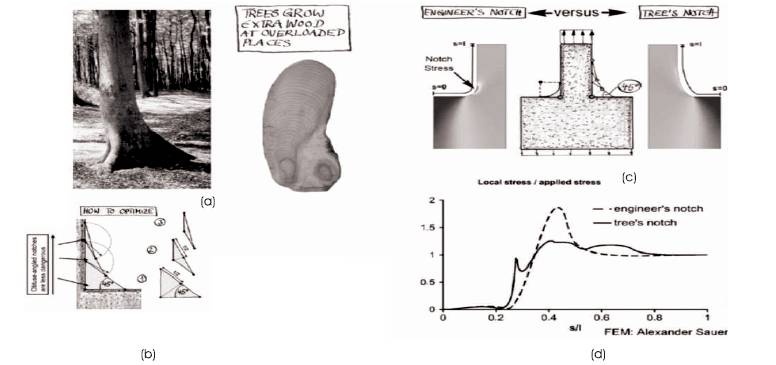
Figure 2. a) Natural Example of Growth Optimisation, b) using Graphical “Tensile Triangles' Techniques to Optimise Design, c) Idealised Design used in Model to Test Notch Stress, d) Results of Notch Stress Test - Significant Reduction (Mattheck, 2006)
The experiment proposed for this investigation aims to determine whether a reaction wood sample could yield superior mechanical properties, derived from its differing microstructure, than a sample of non-reaction wood of the same species. This will require two separate stages; the analysis and idealisation and modelling of wood samples and a Finite Element Analysis simulation.
In order to achieve an acceptable level of scientific rigour, the graphical idealisation process followed a set of controlled guidelines. This would allow for it to be accurately replicated by future researchers. Electron microscopy imagery from different wood samples was assessed by the investigator, and recurring patterns in structure were mapped and recorded. These patterns were then simplified and idealised using graphical methods, before being modelled using Creo Parametric 3.0 to form a control component which could then be subjected to a cantilever beam test within Finite Element Analysis software. A cantilever beam test is commonly used in engineering to measure the flexural strength of a beam, as well as to monitor the behavior of its component materials under both tension and compression (Johnson et al., 2000). The scaling of the internal structures was kept consistent during the modelling process; the cell structures remained proportional to their examples found in nature in order for the experiment to be valid. Each sample beam had the same total dimensions in terms of cross section, length and height to allow for direct comparison during the analysis of the results. Ideally, this test would have run in parallel to a physical experiment. However, due to the time constraints of the research project this was not possible, as sourcing and gathering samples of reaction wood would have been time consuming, expensive and had great potential for error without expert assistance. Figure 3 shows the idealised cross sections generated from the sample found in previous research by Ruelle, 2014.
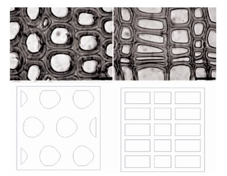
Figure 3. Diagram showing the Original Microscopy Samples (Ruelle, 14) (Top), and their Idealised Cross Sections generated in Creo Parametric 3.0 (Bottom). Reaction Wood is pictured (left) alongside a Standard Wood Sample (right)
The reaction wood sample (pictured left) has visibly thicker cell walls than the standard wood sample, and cells are arranged in a staggered configuration. This results in there being fewer cells per unit area than the standard wood sample. The cells themselves typically have rounded profiles, and follow a helical pattern through the sample. The standard wood sample features a more regular cellular structure. Whilst there is variation between species, these characteristics seem to be consistent; Pillow & Luxford found that “Fibers in pronounced compression wood are circular in cross section and are interspersed with intercellular spaces whereas those of normal wood are nearly rectangular and rarely have intercellular spaces” (Pillow & Luxford, 1937), which adds validity to the experiment. The standard wood model's cells were arranged in rows, with rectangular profiles and much slimmer wall thicknesses. The cell walls followed a straight pattern through the material, rather than a helix. These characteristics were all taken into account when the samples were generated in CAD. The cross sections of these artificial samples are shown in Figure 3 (bottom).
Due to the constraints of the CAD software and the available processing power, the experiment was conducted at 1:100 scale. Each beam measured 100 mm in length and 10 mm x 10 mm in cross section. To ensure that both beams could be compared accurately, both microstructures were enclosed in a 1 mm thick casing. Whilst this would have undoubtedly had an effect on the results of the experiment, this is not problematic as the results are only relevant as a comparison to one another, there is no baseline data with which to compare them to. Furthermore, maintaining this consistent configuration allowed the force moment to be applied in exactly the same place during each test. The cell size was referenced from the original diagram, in which the average cell diameter in the reaction wood sample was approximately 20 μm. This was scaled to a 2 mm diameter of the cavities running through the representative sample. To enable the experiment to run, a number of features had to be discarded as they rendered the samples too complex to undergo simulation on the available equipment. The gelatinous layer found in tension wood was too complex to model, and thus the experiment focused solely on compression wood. Radiuses were originally applied to the internal corners of the standard wood sample; however, these were removed after repeated simulation crashes. The samples were also recreated at a 1:50 scale to achieve a greater cell density, however these tests were not successful.
Finite Element Analysis is a mathematical engineering tool which allows engineers to break down a structure or component into multiple elements. These elements can then be assigned material properties, and each element's performance can be tested individually using known equations. This produces data which can be compiled and used to depict the behavior of the structure as a whole (Bhavikatti, 2010). The use of FEA in this study allowed the samples to be tested under multiple parameters to a high level of precision without the need for physical prototyping. In this case, FEA was advantageous over traditional experimental methods using physical testing rigs as it could be achieved within the short time scale of the study and at minimal expense. The software was also able to run the experiment multiple times to gather a large data set without the need to produce and destroy multiple prototypes.
Creo Parametric 3.0 has integrated FEA functionality, and this was used both for modelling the samples and to undertake the simulations. Using the software to analyse the samples within their respective modelling domains ensured that the chance of file corruption or calibration errors (e.g. incorrect input of MPa/GPa) during transfer would be minimal. Each sample was assigned material properties, which were sourced from data sheets from reputable organisations (Matweb.com, 2016, Wood-database. com, 2016). There was limited data available regarding the properties of reaction wood, and that which was available varied wildly from source to source. Because of this, both samples were treated as having the general properties of pine. This allowed for the cellular structure of the samples to be compared accurately without being affected by differences in performance arising from differing material properties. The data inputs for testing were Young's Modulus and Poisson's Ratio, which were 9.86 GPa and 0.308, respectively. Young's modulus defines the relationship between stress and strain in a solid material, and is used as a measure of a materials’ stiffness (Encyclopedia Britannica, 2015). The more rigid a material, the higher its Young's Modulus will be, whereas more flexible materials will have a lower reading. Young's modulus is instrumental in FEA for mapping deformation under load; the stiffer a material, based on its modulus, the less it will deform. Poisson's Ratio is the ratio of the lateral strain to the longitudinal strain experienced by a material, and is used to map the shrinkage/deformation experienced by a material whilst being stretched, bent or compressed (Encyclopedia Britannica, 2016). One surface at the end of each beam was constrained in all axis of movement using a surface constraint, whilst the other end was subjected to a force of 9.81N (equivalent to a 1kg mass under gravity) vertically, following the Z axis (see Figure 4).
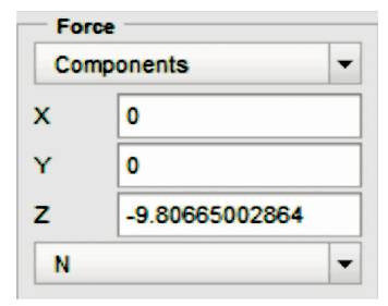
Figure 4. Force Moment Inputs during FEA Calibration. 1kg Mass under Gravity was converted to Newtons (N), and Inputted to the Maximum Available Number of Significant Figures to Increase the Precision of the Simulation
Similarly, Figure 5 shows Von Mises stress diagrams produced during FEA study showing the performance of the standard pine sample (left) against the reaction wood sample (right). Table 1 shows the comparison of peak Von Mises Stresses experienced by each sample.
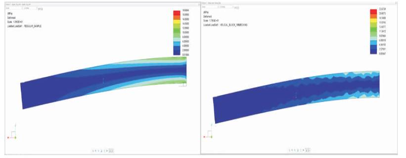
Figure 5. Von Mises Stress Diagrams produced during FEA study showing the performance of the standard pine sample (left) against the reaction wood sample (right)
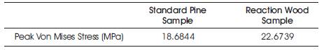
Table 1. Comparison of peak Von Mises Stresses experienced by each sample
The FEA study showed that when a 1kg force was applied, the standard pine sample experienced a peak Von Mises Stress of 18.68 MPa. This is significantly lower than the peak value from the reaction wood sample, which experienced a 21% greater peak stress of 22.67MPa. However, the peak values cannot be used as a representation of the performance of the entire sample, as they were both found on the interior surfaces of corners in close proximity to the constrained surface and in exceptionally small areas (See Figure 6).
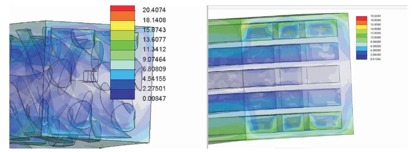
Figure 6. Diagram Comparing Peak Von Mises Stress Concentrations
Whilst the standard pine sample experienced the lower peak stress value, overall it did experience greater stress, which was also spread over a larger proportion of the beam. Figure 6 shows that the standard pine sample experienced stresses of 10-14 MPa, which are much larger and more widespread than on the reaction wood sample. Stresses of the same magnitude were found in much smaller areas in the reaction wood sample, primarily the interior walls of the helical cavities which connected to the outer control surfaces. If the outer control surfaces were ignored, there is little evidence of any significant stress concentrations at all.
Figure 7 confirms that the standard pine sample experienced stresses of greater magnitude over a greater area, as the stress patterns are larger, and extend along a greater portion of the beam. The stress patterns observed in the standard pine sample were uniform in nature and distributed evenly and symmetrically along the beam, whereas the patterns observed on the reaction wood sample are asymmetrical, with ragged transition lines between high and low regions of stress.
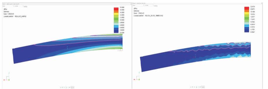
Figure 7. Comparison of Stress Patterns. Standard Pine Sample (left) shows much Smoother Stress Patterns, Reaction Wood Sample (right) shows Erratic Stress Patterns
Figure 8 shows the deformation diagrams produced during FEA study. Standard Wood sample (left) shows 23% greater deformation than the Reaction Wood sample (right).
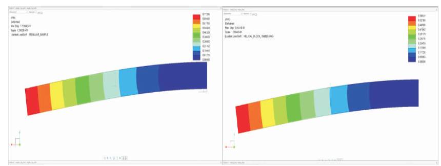
Figure 8. Deformation Diagrams produced during FEA Study. Standard Wood Sample (left) shows 23% greater deformation than the Reaction Wood Sample (right)
Table 2 shows the comparison of peak deformation of each sample.
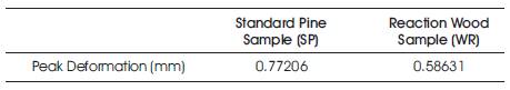
Table 2. Comparison of Peak Deformation of Each Sample
The Creo simulation software allows for deformation diagrams to be increased in scale in order to increase their clarity when dealing with small values. Both diagrams are scaled up in magnitude by 10% to allow for a clearer comparison. Under the same 1kg load, both samples were significantly deformed. The standard pine sample was deformed by 0.77 mm. This was significantly greater than the reaction wood sample, which was deformed by 0.59 mm, a 23% reduction.
Overall, the Reaction Wood sample outperformed the Standard Pine sample during the experiment. Despite having a higher peak Von Mises stress, the reaction wood beam experienced stresses of a smaller magnitude over a smaller area than its competitor and was superior at resisting deformation. These results support the original proposal; that reaction wood may have more favourable mechanical properties than standard timber samples. The smaller regions of stress found in the test and the smaller magnitude of deformation suggests that the reaction wood beam would be able to withstand greater loads than the standard pine beam without reaching its yield point.
Both samples displayed high concentrations of stress in very small regions which were situated on or immediately next to the constrained surface. This was an expected outcome, and can be caused by the experimental setup.
The constraints applied to the model during the simulation rendered the surface at the face of the beam immovable (see Figure 9, right). In reality, tensile stress would be exerted on this surface as a result of the flexion of the upper surface of the beam, and the material would stretch to accommodate this motion, which is known as the Poisson effect. Because this movement was reduced to zero by the parameters of the software, the forces experienced at this intersection were erratic and inconsistent with those of the rest of the sample. In this case, visual assessment was used to discern whether or not the behaviour was abnormal, however in future experimentation this could be more accurately calculated by observing the behaviour of a real sample and comparing the results. It would also be recommended that a 3-point-bend analysis be undertaken using axial rather than surface constraints, and the results of the two tests compared.
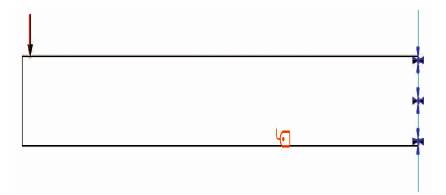
Figure 9. Constraints and Loads applied to Each Sample. The downwards arrow (left) signifies a force moment of 9.81N, whilst the crosses (right) signify an immovable Surface Constraint
The results showed that the reaction wood sample experienced much smaller regions of stress under load, and that these stresses were also of smaller magnitude than those experienced by the standard wood sample. This could be attributed to the reduction of notch stress experienced by the reaction wood sample as a result of the rounded profile of its cavities. Sharp corners experience high concentrations of stress when subjected to load. Radiused edges allow stresses experienced to be dissipated over a larger area, leading to less localised fatigue and with that a lower risk of structural failure. In addition to this, the rounded cavities of the reaction wood sample distributed the compressive load forces around their perimeter and away into the surrounding material. This efficient method of load management is the same mechanism that gives the arch bridge its strength, and contributes to the overall strength of the structure (Darling, 1991).
Whilst the reaction wood sample appeared more effective at distributing stress during testing, this does not necessarily make it the more favourable choice for load bearing purposes. The stress concentration patterns shown in Figure 7, p19 shows clear differences between the two samples. The standard pine sample has long, linear stress concentration patterns which were symmetrical in the XY plane. These patterns had smooth, curved edges which extended along the beam in a uniform manner. This uniform behaviour could be predicted and compensated far more easily and accurately than its competitor. The reaction wood sample exhibited irregular and oddly shaped stress patterns, with peaks, troughs and ragged edges. This is consistent with previous research which described reaction as being difficult to work with due to its irregular nature (Pillow and Luxford, 1937). This also indicates that the timber could behave unpredictably under load, which is undesirable in most applications. It must also be considered that the standard pine sample distributing the stress along a greater proportion of its length could in fact be an advantage. The reaction wood sample's tendency to distribute the stresses applied over a short section with little deformation could be an indication that it is in fact brittle. In contrast, the increased deformation of the standard pine sample could be an effective damping mechanism through which the majority of the material is exposed to stress, rather than one short section being repeatedly exposed, which could accumulate over time, leading to component fatigue. More in-depth experimentation would be required to confirm or disprove this.
The less severe deformation in the standard pine sample was a controversial result, and conflicted with Pillow and Luxford's research which found that reaction wood “deflects more with a given load” than its competitor. However, this supports opposing research which showed reaction wood to have increased stiffness and strength (Wimmer & Johansson, 2014). Overall, this is a favourable outcome, as Pillow and Luxford's study took place in 1939 and lacked the more advanced tools and methods afforded by modern science. This difference in result could perhaps be attributed to experimental error due to the use of methods which were appropriate at the time, but have since become outdated. However, it cannot be ruled out that early experimentation could have yielded accurate results, and the error could instead have arisen due to the aforementioned variation amongst wood samples.
Whilst FEA was an appropriate choice of experimental method within the constraints of the research project, there are questions as to its validity and accuracy. Firstly, when considering the reliability of FEA, “It is necessary to realise that the mathematical formulation is a simplification of reality, and the existence of a physical solution which can be observed in an experiment, does not guarantee that the solution of the mathematical problem exists and has the expected properties” (Babuš ka and Strouboulis, 2001). There is an inherent inaccuracy in any attempt to reproduce an organic object in a digital format. Whilst FEA can provide an excellent approximation, its results can never be relied upon as being truly identical to the behavior of the real article (ibid.).
As discussed previously, some figures generated by FEA can also be inaccurate due to the artificial nature of the constraints and loads applied to each sample. An individual experienced in FEA would be able to minimise this through the tailoring of the elements used in the model. The pattern of the elements can be displayed as a mesh across the surface of the model. This allows the investigator to observe any abnormal element convergences and correct them by editing the mesh pattern. Whilst this can be used to effectively limit the inaccuracy of the simulation, the only way to ensure that the results produced accurately represent the behaviour of real wood would be to test real samples using a physical test rig. There were also issues with the calibration inputs of the FEA simulation. Creo Parametric's FEA suite has the capability to simulate materials with detailed properties, however due to the level of inconsistency in the data found regarding yield points, compressive and tensile stress and damping, the simulation was run using only Poisson's Ratio and Young's Modulus. This raises issues in itself, as;
"A necessary prerequisite [for a successful experiment] is that the mathematic problem has good properties. These are: existence and possibly uniqueness of the solution, and the continuous dependence of the solution on the input data, coefficients of the equation, boundary conditions and the domain.” - (Babuš ka and Strouboulis, 2001)
Without a comprehensive battery of reliable input data, the mathematical conditions of the simulations were suboptimal. Whilst this was still within an acceptable standard of experimentation, further research would benefit from more attention to detail in this area. On the contrary, this more simplistic setup allowed for both samples to be analysed purely as structures, regardless of their inherent material properties, and allowed for judgements to be made on which cell configuration was mechanically superior. However, this decision may have undermined the validity of the experiment further, as the variability in material properties may have arisen as a result of the differences in cell structure and composition, which would need to be accounted for an accurate test. This could have been resolved by conducting physical tests on real life samples, then using the resulting data to calculate multiple stress factors which could then be used to calibrate the FEA. Whilst this would be valid data, it may still be limited in terms of its reach, as each set of calibration data would only apply to the sample it was taken from and would not necessarily be an accurate reflection of other wood samples. In addition, there was insufficient time during this study to schedule and conduct the electron microscopy necessary to provide imagery for analysis. Each sample would have had to be identified, sourced, cut and processed before being viewed under the microscope. This would have had to be taken place under the supervision of a technician, with whom time would have had to be booked in advance. The cost of this process, both monetarily and in time, vastly exceeded the reach of this study.
Prior researchers on this topic highlighted that not only do reaction wood samples display a large amount of variation from species to species, they also have a large degree of variation from sample to sample, even from the same tree (Pillow & Luxford, 1937). Compression wood can be described as either mild or pronounced, and these two types can flow into one and other, and back once again into normal wood (Burns, 1920), making it almost impossible to source multiple consistent samples. This makes it very difficult to draw conclusions on the overall behaviour of reaction wood from a single test, as this small sample could not realistically be considered representative. Perhaps when further research has been conducted regarding the composition of reaction wood and more consistent features have been identified, this will reveal a set of characteristics which would allow for a more representative test. In lieu of this, testing could be undertaken using samples from a variety of trees from each species. The results of these tests could be compared and contrasted in order to determine whether or not there were fundamental cross-species similarities between reaction wood samples. The desire to test a greater number of samples is mentioned in Pillow and Luxford's research, however they described the cost and difficulty of sourcing this quantity of samples as 'prohibitive' (Pillow & Luxford, 1937).
Due to the lack of availability of 3D scans on the cellular structure of reaction wood, assumptions had to be made as to the nature of the helical structure mentioned in prior research (Ruelle, 2014). The chosen helix may have been too deep or shallow in pitch, either of which could produce large differences in the performance of the sample. It was also not possible to demonstrate randomised intercellular spaces, as these features were simply too small and complex for the software to simulate. Simplifications also had to be made to the regular pine sample, as including internal radiuses made the model too feature-dense to simulate. The cells in this sample did not follow a helix, as this was not de