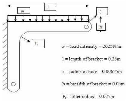
Figure 1. L-shaped Bracket having UDL at its Top Surface [6]
In Mechanical Engineering, a bracket is defined as any component which acts as the intermediate for fixing one part to another, usually larger. Brackets are varied widely in shape, but the prototypical bracket would be of L-shaped metal piece that joins the shelf (the smaller component) and the wall (the largests component): its vertical arm is fixed to one (usually large) element, and its horizontal arm protrudes outwards and holds another (usually small) element. The shelf bracket is effectively the same as the architectural bracket in which a vertical arm mounted on the wall, and a horizontal arm projecting outwards for another element to be attached on top of it or below it [8]. The objective of this paper is to deal with the analysis of L-shaped bracket having uniform distributed load at its top surface and find out the value of von Mises stress, principal stress, and total deformation using ANSYS.
In Mechanical Engineering, a bracket is defined as any component which acts as the intermediate for fixing one part to another, usually larger. In fact, it acts as a mediator between the two and also joins each other. It is defined as a simple rigid structure having the shape of L, one arm of which is fixed to a vertical surface, the other projecting horizontally to support a shelf or other weight. It may be used to support many architectural items, including a wall, balcony, parapets, eaves, the spring of an arch, beams, pergola roof, window box, or a shelf [8].
To enable the outstretched arm and also to support the greater weight, a third arm may be provided to the bracket which runs diagonally between the horizontal and vertical arms, or indeed the bracket may be a solid triangle. By extension, almost any object that performs this function of attaching one part to another (usually larger) component is also called a bracket, even though it may not be obviously L-shaped [8].
Gabriel-Petru Anton, et al. [1] have discussed about the correlation of NVH test-calculation, the Finite Element (FE) model was used for the upgradation of an engine and the vibration level (low and medium frequency range) of the engine/body interface points. The main objective of this approach was to obtain the absolute values of the vibration level (low and medium frequency range) at the interface points using an updated FE model.
S. Irving, et al. [2] have investigated the performance of fatigue of two different bracket connections used in ocean craft for high speed. At constant amplitude, the cyclic tests revealed that the quality of weld within the curved or nested insert had a profound effect upon the fatigue behavior.
Zhang Junhong and Han Jun [3] have worked on the vibratory and acoustic behavior of the internal combustion engine, i.e., highly complex one, consisting of many components that were subjected to various loads that vary widely in magnitude which is operated at a wide range of speed.
S.K. Loh, et al. [4] have focused on Finite Element (FE) performance analysis such as frequency analysis to determine the structural response over a frequency range due to harmonic excitation. The resonant frequency can be predicted on the basis of responses in the frequency domain. Besides that, the static and dynamic vibration analysis gave the maximum structural stress condition under the different static loading and dynamic condition.
The Finite Element Method (FEM) has become a powerful tool for the numerical solution of a wide range of engineering problems which are difficult to solve analytically [5]. Applications range from deformation and stress analysis of automotive, aircraft, building, and fluid flow, magnetic flux, seepage, and other flow problems [6]. With the advances in computer technology and CAD systems, complex problems can be modeled with relative ease. Several alternative configurations can be tested on a computer before the first prototype is built. All of this suggests that one need to keep pace with these developments by understanding the basic theory, modeling techniques and computational aspects of the Finite Element Method. In this method of analysis, a complex region defining a continuum is discretized into simple geometric shapes called finite elements [7]. The properties of materials and the relationships which governed these were considered over the elements and expressed in terms of unknown values at element corners. An assembly process considering the loading and constraints results in a set of equations. The solution of these equations gave the approximate behavior of the continuum.
A bracket is an architectural element or a structural or decorative member. It can be made of different materials, such as wood, stone, plaster, metal, or other mediums. It protrudes from the wall, usually to carry weight and also to "...strengthen an angle” whenever required [7]. Corbel and Console are types of brackets. The application of brackets is in architecture, devices of wood, stone, or metal that projects from or overhangs the wall to carry the specific weight. It may be used as a ledge which support the statue, the spring of an arch, a beam, or a shelf. These are often in the form of volutes, or scrolls, and can be carved, cast, or molded.
On the basis of architectural structure, it is of two types, namely Corbel and Console.
On the basis of materials, brackets are classified into three types such as Metal Brackets, Plastic Brackets and Ceramic Brackets.
The structural analysis of the steel bracket used to support bookshelves is shown in Figure 1. The thickness of the bracket is 3.125 mm. The structure is made of steel with the modulus of elasticity E = 200 GPa. The Poisson's ratio = 0.3. The bracket is loaded uniformly along its top surface. The load is 2625 N/m. The bracket is fixed at its left edge. Let us determine the principal stress and the von Mises stress and deformation using ANSYS.
Figure 1. L-shaped Bracket having UDL at its Top Surface [6]
To find out the stresses (von Mises stress and maximum principal stress) and deformation of the L-shaped bracket, load is distributed uniformly at its top surface and its left face is fixed using ANSYS.
For cantilever beam,
The deformation δ can be calculated as [5],

where,
w - Load intensity
l - Length of bracket,
E - Modulus of elasticity, and
I - moment of Inertia.
The moment of Inertia (I) for rectangular cross section is given by,

where,
b- Breadth of bracket,
d- Thickness of bracket
Stress(σ)can be calculated by [5] ,

M- Bending Moment which is given by,

where,
y- distance from the neutral axis, and is given by,

To solve the given problem, there are some steps using ANSYS:
Inputs for simple geometry are as follows.
Length of bracket (l) = 250 mm
Breadth of bracket (b) = 50 mm
Thickness of bracket (d) = 6.28 mm
Load intensity (w) = 2625 N/m
Inputs for complex geometry are as follows.
Length of bracket (l) =250 mm
Breadth of bracket (b) = 50 mm
Thickness of bracket (d) = 6.28 mm
Load intensity (w) = 2625 N/m
Fillet radius (Fr) =25 mm
Diameter of circular hole= 12.5 mm
Diameter of circular cross section=50 mm
The models of the simple and complex geometry are shown in Figures 2 (a) & (b). After modelling, meshing is required as shown in Figures 3 (a) & (b).
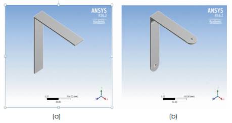
Figure 2. (a) Simple Model, (b) Complex Model
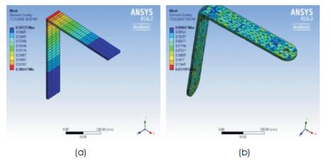
Figure 3. (a) Simple Mesh, (b) Complex Mesh
The left edge of the simple and complex bracket are fixed as shown in Figure 4.
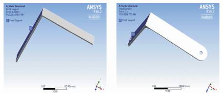
Figure 4. Fixed Support
The uniformly distributed load is applied at the top surface of both geometries as shown in Figure 5.
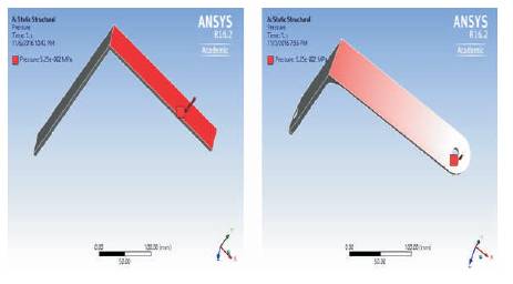
Figure 5. Applied Load at the Top of Geometries
After fixing the support and applying the load on the bracket, the maximum deformation occurs at the free end of the bracket as shown in Figure 6. The maximum stress occurs at the fixed end of the bracket as shown in Figure 7. The maximum principal stress also occurs at the fixed end of the bracket as shown in Figure 8.
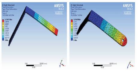
Figure 6. Deformation
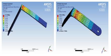
Figure 7. Equivalent Stress
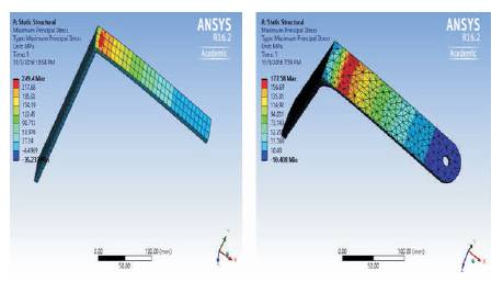
Figure 8. Principal Stress
Table 1 and graphs of Figures 9 and 10 show the comparison between the results of calculated value and software value of simple and complex geometry.
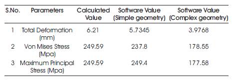
Table 1. Comparison between the Results
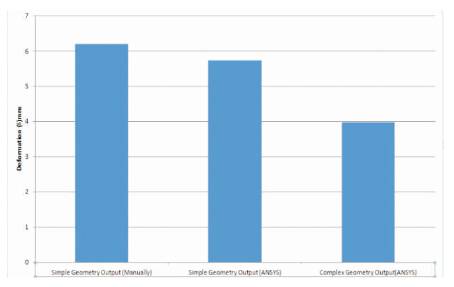
Figure 9. Variation in Deformation
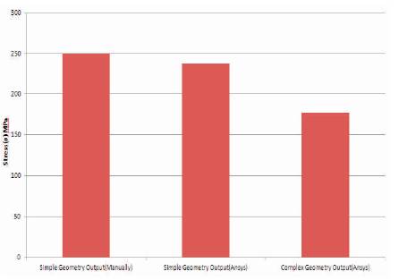
Figure 10. Variation in Stress
From the above analysis, the value of total deformation, von Mises stress, and maximum principal stress were found out with the help of ANSYS and the data was validated theoretically. Both are found to be in good agreement with each other.
As there are two geometries, one is simple and the other one is complex. From the analysis, it is found that the value of stress and deformation of complex geometry is less than the simple geometry.
The values show that the purpose of complex geometry achieved for the given data design is safe.