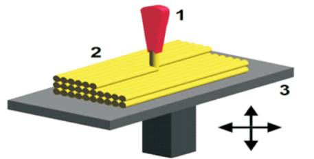
Figure 1. Fused Deposition Modeling
A Camshaft is a shaft on which a cam is fastened or a cam forms as an integral part. It is an important component of an internal combustion engine which plays a major role in operating the valves. 3D printing is a process of making three dimensional solid objects from a digital file. An object is created by laying down successive layers of material until the entire object is created. Hence it is called as 3D printing or additive manufacturing.
The main objective of this work is to produce prototype of two wheeler camshaft and helical camshaft which are designed in Creo Parametric 2.0, analyzed using ANSYS workbench 2016 and 3D printed using Makerbot Replicator Z18. Poly Lactic Acid (PLA) is the material used in 3D printer to produce the camshaft.
3D printing allows innovative ideas into successful end products rapidly and efficiently. 3D printing is still on a developing stage where more research and investigations are being in process. This work concludes that camshaft with helical cam lobe is more favorable as compared to spherical lobe.
3D printing is a process used to produce prototypes of a newly created design in order to carry out further advancement or changes in the design. 3D printing is a material addition process which makes use of additive manufacturing technology in which the component is produced by adding the material layer by layer to produce components in mass production directly. Camshaft produced by conventional and other unconventional machining processes requires a series of processes to obtain the final product which requires a lot of power, space, cost and time. In this work, it is proposed to produce the camshaft by an additive manufacturing process using 3D printing. 3D printing is an additive manufacturing process in which a three dimensional product or component is produced from a three dimensional model using Computer Aided Design (CAD) software in a very short period of time. 3D printing is also called as rapid prototyping. One or more materials can also be added layer by layer in a plane. The 3 Dimensional models can be created in various CAD software and these are fed into the 3D printing machine. It is fed in .STL format so that the 3D printing machine reads it.
Rapid prototyping process is mainly classified into six types:
In this work, Fused Deposition Modelling (FDM) is used. In this method, material is laid down in layers and the material is supplied in the form of plastic filament or a metallic wire. In Fused Deposition Modeling, a movable nozzle has only X-Y movement. It deposits a molten polymeric material onto a substrate. The material is heated slightly above its melting temperature. It is chosen in order to get it solidified within a very short period of time after extension and cold-welds to the last formed layer. The modern Fused Deposition Modeling process involves two nozzles, one for the part material and the other for support material. The support material is of poor quality and it can be broken easily. In more advanced process, water-soluble support structure material is used. The additional structure can be deposited with less density by providing gaps between the consecutive roads. Figure 1 shows a detailed schematic diagram of Fused Deposition Modeling (FDM) process.
Figure 1. Fused Deposition Modeling
Prachi [5] has worked on 3D Printing. 3D printing is a quickly expanding field, which can be used to prototype, create replacement parts, print prostheses, and medical implants. 3D printing is a category of rapid prototyping technology. It reduces the complex process of printing into a single and simple way. It not only has applications in rapid prototyping, but also has in other technologies like medical, arts, and outer space.
Pandey [6] has worked on Rapid Prototyping Technologies, Applications, and Part Deposition Planning providing an overview of Rapid Prototyping technology in brief and emphasizes on their ability to shorten the product design and development process. Before the start of full production, prototype is usually fabricated and tested. Latest trend of prototyping, i.e., Rapid Prototyping using layer-by-layer material deposition, started during early 1980¢s with the enormous growth in Computer Aided Design and Manufacturing (CAD/CAM) technologies. Some important factors to be considered before starting part deposition for proper utilization of potentials of Rapid Prototyping processes are also presented.
Schneider, et al. [3] worked on characterization of an optimized model manufactured by rapid prototyping. The main issue of this paper is the integration of simulation and optimization in the first phase of a manufacturing process to take into account the characteristics of additive manufacturing in particular to save material. In the rapid prototyping area, technologies used a construction material and a support material to manufacture geometry. The support material is sometimes conserved in the prototyped part and cleared on its outside. This elimination of support material involves a cost for the user. They have presented various models generated by numerical optimization. The results were successful to a methodology applied to industrial cases as the injection mould.
Thorat, et al. [4] worked on Design & Analysis of Camshaft, which is one of the key parts or components in the engines of automobile and other vehicles. This work is to design camshaft analytically, its modeling and analysis under 3D modeling or Fused Deposition Modeling (FDM). The model is drawn in 1D, 2D or 3D space in the appropriate units. The model may be created in the pre-processor or it can be imported from another CAD drafting package via a neutral file format. Modal analysis of existing camshaft is carried out. Comparing analytical and analysis results, it is clear that designing of camshaft is correct and safe.
Dhavale, and Muttage [2] studied the modeling and fracture analysis of camshaft. In this paper, camshaft is used in the engine for the transfer of motion to inlet and exhaust valve. If transfer of motion is not proper, then the strokes of the engine will not be done in a proper way. It also affects the performance of engine. It is seen that, the analyzed camshaft is fractured after a very short period of usage of the car. The failure is occurred as a sudden fracture very close to journal location, where there is a stress concentration. The main reason of the fracture is determined as a casting defect. As the failure was related to a material production problem, it is likely to affect more than one vehicle. So, the camshaft of vehicles manufactured from that particular series of camshaft should be replaced. Also, the non-destructive testing procedures of the component supplier should also be improved as the defect can easily be detectable by standard non-destructive techniques.
Jaiganesh, et al. [1] worked on manufacturing of PMMA Camshaft by Rapid Prototyping. Rapid prototyping is a technique used to quickly fabricate an assembly, components or parts using three-dimensional Computer Aided Design and Computer Aided Manufacturing (CADCAM). Camshaft is a component in which a set of cams become an integral part to a shaft placed in its respective positions and directions according to the application of the particular camshaft. The main advantage of this type of manufacturing is that more number of precise components are obtained. This allows multiple cams to be produced at a time by the help of a powerful laser.
Mallikarjuna et al [7] worked on the Design, Manufacturing and Cost Estimation of Camshaft used in two wheelers. This shaft also provides the drive to the ignition system. In this paper, a camshaft is designed for a two wheeler engine by using theoretical calculations. Cam profile is designed by using the calculations. A 3D model of the Camshaft is created using modeling software Pro/Engineer. For manufacturing, camshaft casting process is used as it is useful for bulk production. Total mould base is to be designed for the camshaft which is ready to go for production. CNC Program is to be generated for both core and cavity using roughing and finishing processes.
Dheeraj and Mahaveer et al [8] reviewed development of rapid prototyping. It has developed into one of the utmost growing new technologies. Prototypes are building in just a few hours from a CAD file, in which the geometry of the model is defined in 3D. It gives the designer possibility of verifying the shapes of the product, validate if it fits into the assembly with the desired functions. It cuts down the required time to design a product. It has been used in Mechanical design, aerospace medical application, arts, and architecture and it is a potential tool for the mechanical field.
Villalpando, et al [9] employed to create physical models from three-dimensional (3D) Computer Aided Design (CAD) models. Fused Deposition Modeling (FDM) is an additive fabrication process that builds a product from thin layers of extruded filaments of a semi-melted thermoplastic. The mechanical properties depend mainly on variable factors, such as the material's depositing orientation, the Filament's flow rate, the raster's separation, and the extrusion temperatures. These parameters control the Part's meso structure (when the extruded fibers' scale approximate to 0.1 mm) characteristics and influence the fiber-to-fiber bonding. The dependence of the FDM material's properties provides the designer the ability to optimize the mechanical performance while modifying the part's meso and macro structures. The two main FDM manufacturing strategies (solid and shell) may be used distinctively; however, there are applications where the solid build strategy may not be necessary and even problematic. When there is a thick wall - thin wall blend, this configuration may lead to distortion.
From the literature study, it is found that very few works have been done on design, analysis, and 3D printing of the camshaft. Therefore, this work has been carried out with the following objectives.
In this work, traditional design process is employed to design the camshafts. Creo software is used for 3D modeling of the shafts and ANSYS is used for analysis of the shafts. MakerBot 3D printer is used to print the camshafts.
Figures 2 and 3 are the camshaft models created in Creo Parametric 2.0 software respectively. They are designed with reference to Hero CBZ Xtreme camshaft. It is proposed to replace this shaft with helical camshaft as shown in Figure 3. The specification of the engine and dimension of the camshafts are as follows.
Power = 10.6 kW
Speed = 8500 rpm
Torque (max) = 12.80 Nm
Bore = 57 mm
Stroke = 58.6 mm
Cubic capacity = 150 cc
Cam width = 14 mm
Camshaft diameter = 22 mm
Journal diameter = 28 mm
Base circle diameter = 25.6 mm
Angle = 30
Area of piston = (π/4)D^2 = (π/4)57^2
Angular velocity = (2πN)/60 = 628.3 rad/sec
Total lift of cam = 5.829 mm
For Modified camshaft,
For an angle = 35
Lift of helical cam = 11.33*35*(π/180) = 6.8 mm
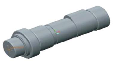
Figure 2. Hero CBZ Xtreme Camshaft
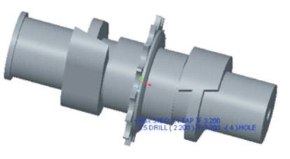
Figure 3. Helical Camshaft
After the modeling, mesh is applied to the model for dividing the analysis continuum into a number of discrete parts or finite elements. The finer the mesh, the better are the results, but longer is the analysis time.
The loading may be in the form of a point load, a pressure or displacement for the stress (displacement) analysis, temperature or heat flux in a thermal analysis and fluid pressure or velocity in a fluid analysis.
Apply a load to the model, then in order to stop it accelerating infinitely through the computers virtually (mathematically known as a zero pivot), at least one constraint or boundary condition must be applied.
Static structural analysis is the determination of the effects of loads on physical structures and their components. The maximum stress obtained at bearings is 0.0017017 MPa as shown in Figure 4. The total deformation at cam lobes is 4.1345 e-6 as shown in Figure 5.
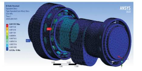
Figure 4. Static Structural Analysis of Hero CBZ Xtreme Camshaft
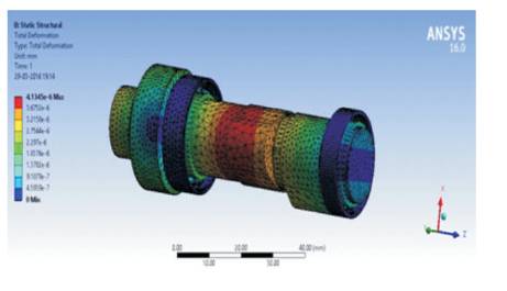
Figure 5. Total Deformation of Hero CBZ Xtreme Camshaft
Modal analysis is used to determine a structure's vibration characteristics, i.e. natural frequencies and mode shapes. It is the most fundamental of all dynamic analysis types and is generally the starting point for other more detailed dynamic analysis. The maximum total deformation frequency observed at shaft is 304.27 Hz as shown in Figure 6.
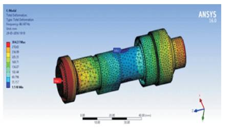
Figure 6. Modal Analysis of Hero CBZ Xtreme Camshaft
The 3D models prepared using Creo parametric 2.0 software and these are converted into Stereolithography format i.e. STL format, Later on, these models are transfered to 3D printer for STL file manipulation. A user copies the STL file to the computer that controls the 3D printer. The user can change the size and orientation of the component for printing. This is similar to the way to set up a 2-D printout to print 2-sided or in landscape versus portrait orientation.
In this work, MakerBot Replicator Z18 is used for printing of three dimensional objects. It works on Fused Deposition Modeling process. The material used for printing the camshafts is Poly Lactic Acid (PLA) material. MakerBot Desktop translates 3D design files into instructions for the printing of component.
Figure 7 shows MakerBot Replicator Z18. The MakerBot Replicator Z18 will melt PLA Filament and squeeze it out onto the build plate in thin lines to build the object layer-bylayer. With the huge build volume of the MakerBot Replicator Z18, this part of the process can take a long time. During printing, the heated build chamber will allow the extruded PLA to cool slowly, minimizing warping, and curling. The model at the center of a gray rectangle is shown in Figure 8, which is the MakerBot Desktop's representation of 3D printer's build plate and other features are also visible in the prepare view. The features are:
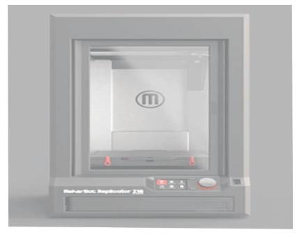
Figure 7. Makerbot Replicator Z18
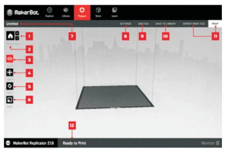
Figure 8. MakerBot Desktop's representation
In order to start printing of camshafts with the replicator Z18, a sequence of steps are recommended as given below:
Figures 9 and 10 show the progress of printing on desktop of 150 cc camshaft and helical camshaft, respectively.
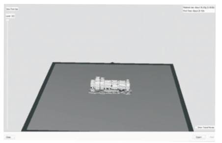
Figure 9. 150 cc Camshaft
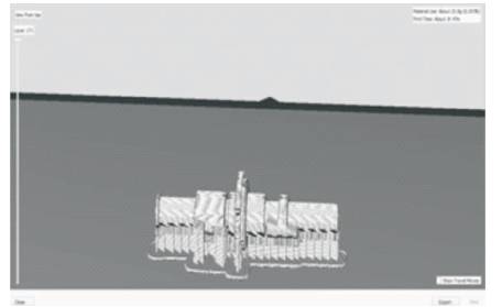
Figure 10. Helical Camshaft
Figure 11 shows 150 cc camshaft with support material. Figures 12 and 13 show 3D printed overhead camshaft and helical camshaft, respectively. Finally, remove the raft and support material carefully from the model.
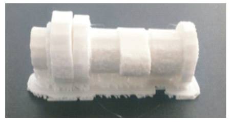
Figure 11. 150 cc Camshaft with Support Material
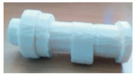
Figure 12. 3D Printed Overhead Camshaft
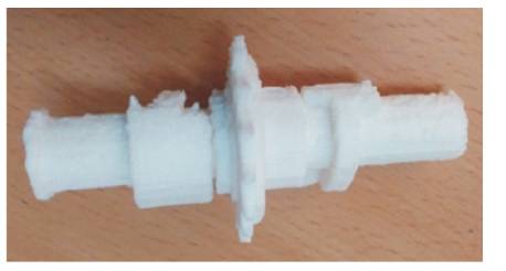
Figure 13. 3D Printed Helical Camshaft
3D camshafts are successfully printed with PLA on MakerBot Replicator Z18. The PLA is extruded around 215 oC and the components are printed using a 0.30 mm layer resolution, which give excellent bonding between each layer. Also, the door vent is kept closed at all times because when it's open, the air will flow in, which may weaken the bond. Camshafts are printed using Poly Lactic Acid (PLA) to achieve good surface finish. It can be immersed in potassium hydroxide Tetrahydrofuran THF, Acetone, etc. As the support material and the material used for printing the camshafts are same, it would not be proper to use those chemicals for better surface finish. Instead emery papers are used to finish the surface.
From this, the 3D printing technology can be implemented in producing and replacing of automobile components, as it is faster, economic, and reliable.
Improving performance of cam is done by increasing the amount of lobe lift. Designing a cam profile with more lift results in increased duration in the high lift regions, where cylinder heads flow the most air than short duration cams with relatively high valve lift can provide. From this work, the following conclusions are drawn.