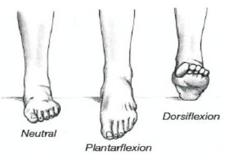
Figure 1. Dorsiflexion and Plantarflexion of the Foot
The aim of this study is fabrication of new design and stress analysis of Ankle-foot orthoses (AFO) on gait parameters of foot drop patients. In the initial phase, patients by age 3-5 years, who are suffering from cerebral palsy and foot drop disease are selected. An AFO is orthosis that is specifically designed to modify the functioning of the ankle and/or the foot. AFOs are produced in various forms composed of different materials, and prescribed with a wide variety of aims. In market, AFOs in polypropylene & polyethylene materials are available which are used by children. The present AFO design is used by patients who are facing excessive heating and sweating problem. After discussing with Patients and Orthotist (who prescribed AFO to patients), the authors have tried to overcome the problem with the new design of AFOs & done the Finite Element Modelling and stress analysis. The result shows that this new design is very close to the actual product.
Ankle-foot orthoses (AFOs) are orthoses that include the ankle joint, the whole or part of the foot. AFOs are meant to control movement, correct (misshapen or missing body part), and makeup for the weakness. AFOs can be designed with (good) enough mechanical lever arms to control the ankle complex directly and to influence the knee joint indirectly [1-4]. AFOs are now the most widely used orthoses in the United States (US), accounting for 26% of medicine based practice by certified orthotists, double that of any other type of orthosis.
To understand how AFOs work, it is necessary to first understand two standard movements that happen at the ankle joint "dorsiflexion" and "Plantarflexion" which are shown in Figure 1. Plantarflexion is the movement the ankle joint made when the toes point downward. Dorsiflexion is the movement the ankle joint makes when the foot points upward. This movement needs to happen when the foot comes off the ground so that the patient does not drag their toes. Patients with drop foot usually have a partial or complete weakness of the muscles that dorsiflex the foot at the ankle joint [5-7].
Figure 1. Dorsiflexion and Plantarflexion of the Foot
Serdar Kesikburun and his colleagues assess the effect of ankle foot orthosis on gait parameters and functional ambulation in patients with stroke and found that walking speed, cadence, and ankle dorsiflexion at initial contact and midswing were significantly increased while walking with AFO compared to walking barefoot [15].
Esquenazi A and his colleagues investigated the effect of ankle-foot orthosis on temporal spatial parameters and asymmetry of gait in hemiparetic patients and found that the use of an AFO improved the symmetry of several temporal spatial parameters of gait, and consequently, the gait patterns of these hemiparetic patients were enhanced [16].
Franceschini M and his colleagues assessed the effects of an ankle-foot orthosis on spatiotemporal parameters and energy cost of hemiparetic gait and found the orthosis significantly improved self-selected speed [17], stride cycle, stance and double support and reduced energy cost of walking without affecting cardiorespiratory response. Moreover, a significant correlation was found between the improvement of double support and the reduction of energy cost [8-10].
Prototyping is the process of building pre-production models of a product to test various aspects of its design. There are limitations of traditional prototyping methods, such as the time required to fabricate the prototype, the overall complexity of the object, and the extreme labour intensity of traditional prototyping method. Fast Making, an early model, is the process of creating an object directly from its digital representation in CAD/CAM system. The main benefit of this process had reduced the time to produce an early model, which in turn speeds up the whole development process. Fast Making, an early model, has also been referred to as solid free-form manufacturing; Computer Automated Manufacturing, and layered manufacturing. Fast Making model, has obvious use as a vehicle for seeing (in your mind). Also, RP models can be used for testing, such as when a (airplane wing shape) shape is put into a wind tunnel. RP models can be used to create male models for tooling, such as silicone rubber models and investment casting. Sometimes, the RP part can be the final part, but usually the RP material is not strong or strong enough. When RP material is good, highly confusing shapes (including parts nested within parts) can be produced because of the nature of RP.
FDM is the second most widely used fast making early model technology, after stereo lithography. A plastic thin thread, about 1/16 inch in (distance or line from one edge of something, through its center, to the other edge), is unwound from a coil (A), and supplies material to an extrusion nozzle (B). Some setups of the machinery have used plastic pellets fed from a hopper rather than a thin thread. The nozzle is heated to melt the plastic and has a (machine/method/way), which allows the flow of the melted plastic to be controlled. The nozzle is mounted to a mechanical stage (C), which can be moved in flat/leftand- right and up-and-down directions. FDM Fortus 400mc model is used for making an early model, which is shown in Figure 2 (a) and prototype mode in Figure 2 (b).
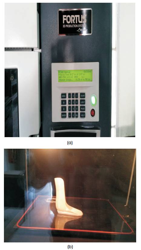
Figure 2. (a) Rapid Prototyping (FDM) Machine, (b) Prototyped AFO Model
A customized AFO design can be achieved only if stiffness can be predicted with a certain degree of confidence. Polypropylene & Polyethylene AFOs have definitive well documented advantages over the conventional designs, but their mechanical behavior under service conditions cannot be easily predicted. The thesis has to ensure mechanical behavior during the life cycle of the product, promoting the best function, and quality of life to the user with necessary safety [11] . Although with a controlled production process, some cases of fractures on the ankle region have been reported. In order to prevent this situation, one need to better understand the effect of geometry, material and production process on the arising of fracture and product malfunction. The use of FEA – Finite Element Analysis, has to analyze mechanical behavior and properties of AFOs, and can therefore be used for the purpose of this study as mentioned in Figure 3.
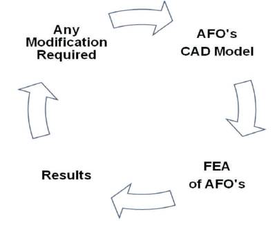
Figure 3. Ankle Foot Orthosis Design & Analysis Flow Process
Since the model geometry is very complex, a simplified geometry is constructed on the basis of measured parameters like: foot support length (1) and width (2), leg height (3) and back curvature (4), and the ankle lateral (5) and media (6) curvatures and medial plantar arch (7), is adopted – as shown in Figure 4 as a simplified geometrical model [12-14].
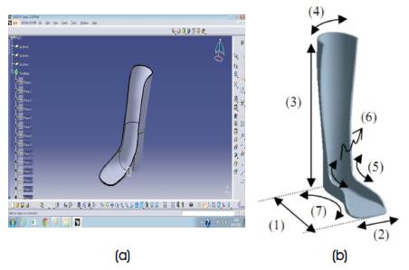
Figure 4. (a) CATIA Model, (b) Parameter Identification
In Finite Element Modelling, the authors created Four different models by changing the design of Ankle-foot orthosis and then the shell type structure was generated assuming same material properties that varies with forces in ANSYS software after linking all four designs & actual part model of Ankle-foot orthosis as shown in Figure 5.
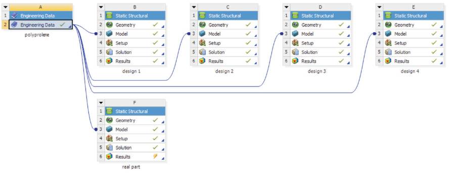
Figure 5. Linkage of Four Design & Real Part of Ankle-foot Orthosis
The results presented are simply a strong sign of the FEM possible ability to be/possible ability as a test/evaluation and design tool before prescription. Developed through the procedure, an orthotist can get reliable information on the (twist/bend/change the shape) action dependent stiffness (features/qualities/traits) of an initial AFO design. If these (features/qualities/traits) do not meet the patients' needed things, the modelling and analysis (success plans/ways of reaching goals) put into use are (good or well enough) (able to do many different things well) to allow virtual changes so that best design could be accomplished or gained with effort.
In this research, the authors have taken the Ankle-foot orthosis for children with Age group of 3-5 years. Polypropylene fabricated ankle-foot orthosis is available in market for patients' use. Four different designs, including the real part of an Ankle-foot orthosis in commercial design software CATIA V5 design software are created.
The number of later model generations will change/differ depending on the sophistication of the results desired. Now it maybe unlikely that all non-linear limits/guidelines of the human body can be included in an FEA model, mainly because all properties are not yet known, compared with bench and medicine-based findings, will however show that almost the same behavioral results are possible. The person who works to find information should not be overly concerned with the small details of the model limits/guidelines. Thinking about the variances between people, a summary covering most of the noted effects should be the goal.
The purpose of the model to examine system behavior when changes are made, such as the effects of geometric and material modifications, although the actual behavior may not be exactly the variations due to changes in the model or human system. After modelling, the authors have done the Finite Element Analysis shown in Figure 6, by taking the maximum and minimum density properties of Polypropylene & Polyethylene for all models, including global meshing of the CATIA model. The mechanical property values of polypropylene, polyethylne, and polyamide material used in FE simultation are shown in Tables 1, 2, and 3 respectively. Design IV is close to the real part of Ankle-foot orthosis.
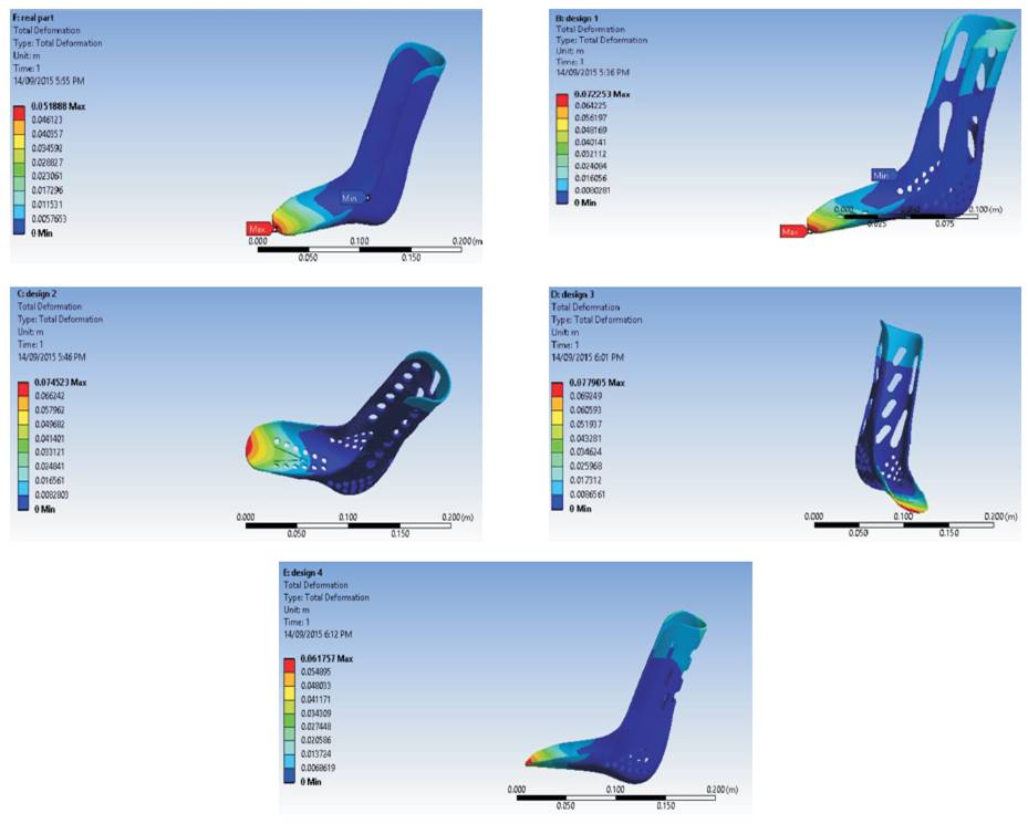
Figure 6. Stress Anaylsis Results for Polypropylene AFO Real Part & Alternate Designs
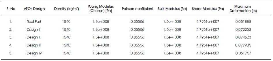
Table 1. Mechanical Characteristics of Polypropylene Material used in FE Simulation
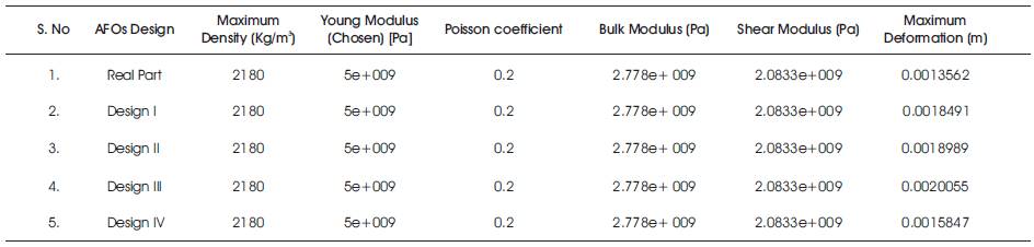
Table 2. Mechanical Characteristics of Polyethylene Material used in FE Simulation
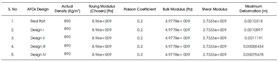
Table 3. Mechanical Characteristics of Poly-amide Material used in FE Simulation
The results of this study provided a solution for excessive sweating and heating of Ankle-foot orthosis to patients having age group Three - Five years during changing the weather conditions for long usage. The authors have created the actual part and new design for patients in commercial design software CATIA V and done the Finite Element Analysis inorder to find which design is closer to the actual part of AFO. During Finite Element Analysis, it is found that Design IV is closer to real part in terms of material deformation and solving the patients' problems. In Design IV, the authors have given extra space for proper air circulation and ventilation which will require more forces for material deformation, which is shown in the result chart.
The author(s) declared no potential conflicts of interest with respect to the research, authorship, and/or publication of this article.
The author(s) received no financial support for the research, authorship, and/or publication of this article.