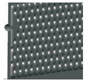
Figure 1. Dimple Plate
This paper deals with the study of different types of heat exchangers used in engineering industries such as plate type, shell and tube, radiator and cooling towers. The effect of different performance and geometrical parameters to obtain optimal heat transfer rate is studied. The main parameters are temperature of inlet and outlet working fluids, mass flow rates, pressure drops, fin design, coolants used and flow consideration. The optimal design of the geometry can be obtained easily and effectively by using CFD tools to experiment a compact and efficient model.
Heat transfer is the process where the heat transfers from one body with high temperature gradient to another at lower energy by radiation, conduction, convection or a combination of these methods. Heat exchangers are the devices used to transfer the heat between two fluids flowing at different temperatures separated by a solid wall. Application of heat exchangers can be used for either cooling (refrigerators) or heating (space heating) the required fluid. Heat exchangers can be classified into many types based on the fluid’s flow direction such as parallel flow, cross flow or counter current flow. Heat exchangers can also vary on the design of construction with numbers of tubes, presence of hot plates, etc.
The objective of this paper is to study the different types of heat exchangers and the effect of different parameters that affects the heat transfer coefficient. The parameters like inlet and outlet temperatures of working fluids, mass flow rates, pressure drops, fin design, coolants used and flow consideration. The optimal design can be obtained by varying the geometry and verified by CFD analysis.
They are based on construction features, heat transfer mechanisms, flow arrangements, transfer process, number of fluids, and surface compactness [34, 37]. They are made up of thin plated sheets joined with a small gap between them, separated by a small rubber gasket. They are mostly used in domestic refrigeration applications as it has large surface area and fluid can flow through the opening between the corners of each rectangular plate effectively. Alternate fluid channels for hot and cold fluids make the heat transfer more effective than the others. A particular design approach has been developed, where excessive rows and columns of equally spaced staggered dimples were provided to enhance the heat transfer rate and lower the pressure drops (Figure 1). Figure 2 shows the flow direction that was turned to 180o and internal flows' wall angle of 45o makes the flow to have longer heat transfer length.
Figure 1. Dimple Plate
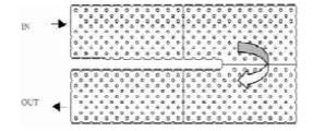
Figure 2. Flow Direction
Aluminium dimple plates are used for withstanding fouling and corrosion. For increasing the load handling capacity, numbers of such plates are assembled in parallel series. The essential parameters such as pressure drop, heat transfer coefficients are studied by CFD analysis.
Figure 3 shows the pressure & temperature distribution of internal fluid flows. It showed that the better performance of water used as a heat transfer agent inside the plate due to extreme levels of flow impingement.

Figure 3. Pressure and Temperature Distribution
It consists of multiple tubes mounted inside a cylindrical shell through which the liquid flows. First fluid flows through the tubes and the other fluid flows over the outside of tubes for exchanging the heat. Tube bundles, shell, front-endhead, rear-end-head, baffles, and tube sheet form the major components. Common types of shell-and-tube heat exchangers are AES, BEM, AEP, CFU, AKT, and AJW. The heat transfer rate can be enhanced by some arrangements such as baffle orientation, fin and corrugation arrangement [10].
The size of the heat exchanger is made as small as possible to reduce the cost of the equipment [7]. The relationship between the different cross section of tube bundle shape and heat transfer, pressure drop was studied for triangular, rectangular and round shape (Figure 4). CFD simulation and analysis were carried for three configurations and concluded that rectangular cross section shape produces less pressure drop.
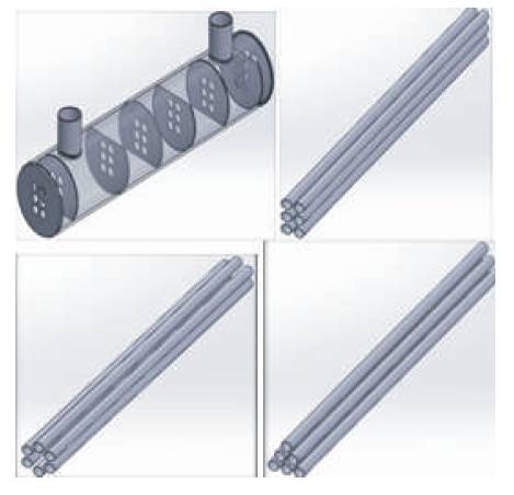
Figure 4. Shell and Tube Bundle Arrangements
A simplified differentiation model was proposed to calculate more accurately the temperature distribution of the heat exchanger and compared with cell model and HTRI program (Figure 5).
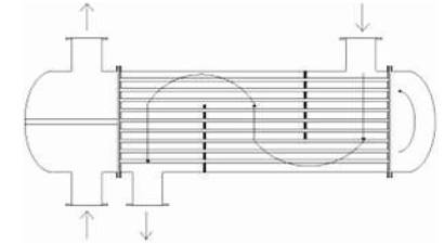
Figure 5. Schematic of Shell and Tube Heat Exchanger
Radiator is one of the heat exchangers designed to transfer heat from the hot liquid that flows through the tubes mounted parallel and gets cooled by the air blown through it by the fan. The fins are used to transfer the heat from the tubes to the flowing air. Figures 6 (a) and (b) show the simple schematic of the radiator and tube fins. The hot fluid from the engine block fills the tube banks and makes a single pass through the radiator [18]. The fan forces the cool air across the radiator core and the air produced due to the motion of the vehicle. The cool air absorbs the heat from the hot liquid. The geometry of single tube and the fluid flow through the tubes and two rows of fins are shown in Figure 5.
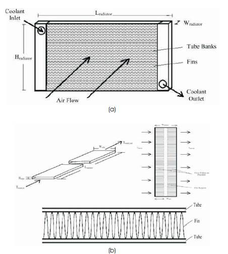
Figure 6. Schematic Diagram of (a) Radiator Shell (b) Tube & Fins
Sinusoidal geometry of fins was assumed to be straight for simplification. Experimental and theoretical analysis were compared to calculate the outlet temperature for calculating the output for the input parameters considered, viz. convective heat transfer coefficients, overall heat transfer coefficients, Number of Transfer Units (NTU), effectiveness, and heat transfer rate. Compared to rectangular radiators, a circular radiator design was developed with varying number of tubes [23]. The efficiency can be improved in the circular radiators as air drawn by the fan, (Figure 7). A circular radiator was proposed to design as a compact and effective type.
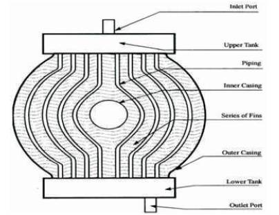
Figure 7. Schematic of Circular Radiator
The different factors that affect the heat transfer rate are explained below.
The performance parameters that affect the heat dissipation rate, coolant pressure drop, and cooling air pressure drop are coolant inlet temperature, cooling air velocity, coolant volume flow rate, etc. [39]. The experimental design can be optimized by quadratic form polynomial regression equation. Effects of (operating parameters) inlet coolant temperature and volume flow rate on heat dissipation rate and pressure drop was studied. It was concluded that heat dissipation rate increases as coolant inlet temperature, volume flow rate, and cooling air velocity increases. The pressure drop of air and coolant is directly proportional to air velocity and coolant volume flow rate. Performance of the radiator was predicted experimentally using NTU method to obtain the coolants' Nusselt number and heat transfer coefficients [28]. Trial and error method was considered for calculating coolants' total effectiveness coefficient and air side heat transfer coefficient. The pressure drop and Colburn factor was estimated. Figure 8 shows the values of Nusselt number versus Reynolds number of the coolant. Compared with actual conditions, heat transfer got 50% improved air distribution in wind tunnel.
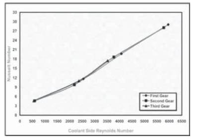
Figure 8. Nusselt Number Vs Reynolds Number
Comparative study between conventional rectangular and circular shaped radiator was conducted experimentally and numerically and found the circular radiator with increased number of tubes produced an effective heat transfer rate with increased pressure drop [2]. The pressure and temperature contours of rectangular and circular radiator are presented in Figure 9.
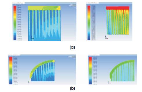
Figure 9. Contours of (a) Rectangular Radiator, (b) Circular Radiator
Fluid flow characteristics are analysed in Fluent to observe the flow phenomenon and calculate the overall pressure drop and mass flow rate of air and coolant in the automotive radiator [35]. The contours of pressure and temperature are presented in Figure 10.
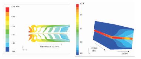
Figure 10. Contours of Air and Water Flow Direction
The uniform and effective air flow distribution in the frontend shield of the passenger car was studied by varying the shielding methods such as horizontal, vertical, side to side and side to centre [36]. Experimental and CFD simulations prove that compared to all the other methods, horizontal front-end shielding produced the uniform air flow distribution for cooling effectively and is represented in Figure 11.
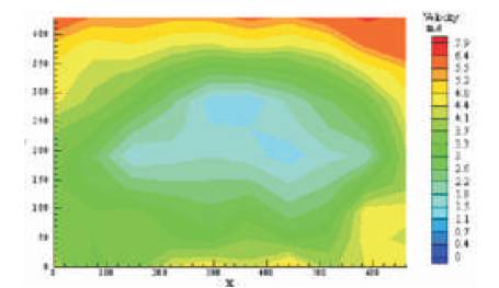
Figure 11. Air Flow Velocity Distribution for Horizontal Type Front Shielding
Fins with alternate layers form a compact heat exchanger [16].
Different types of fins such as plate, louver, convex louver, and wavy forms are used according to the applications. Figure 12 represents the louver type fin which is used in an automotive radiator. The flow and heat transfer in a cross flow heat exchanger are predicted using finite volume based CFD technique. The results of pressure and temperature contours of the computational domain are observed in Figure 13.
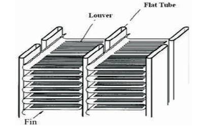
Figure 12. Louver Type Fin
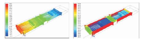
Figure 13. Contours of Louver Fin Wall Surfaces
The effect of fin and louver thickness variation on water and air outlet temperature were studied. It was observed from the analysis that by increasing the louver, fin, thickness, the overall heat transfer increases. The numerical study of geometrical parameters and the other parameters that influence the working conditions are mass flow rate, inlet temperature of working fluids, fin spacing, louver angle, pumping power and overall heat transfer coefficient [32]. Compared to U-flow, I-flow was found better. Cooling capacity can be increased by increasing the mass flow rate of air, coolant & pumping power, decreasing the air inlet temperature. The optimum dimensions of a centralheating radiator were considered for maximizing the heat transfer rate [33]. The heat transfer coefficient of the inner fluid was expressed by using Dittus – Boelter correlation. The total heat transfer rate between the tube and inner fluid was calculated by applying Newton's law of cooling to obtain the effective volume fraction by fixing all other thermal properties. The complex geometry problem has been divided into simple three one-dimensional fin problems to evaluate the temperature distributions within the fins and at the junction of the fins. The effects of inner fluid temperature and room temperature on optimum design to obtain maximum heat transfer rate was observed in Figure 14.
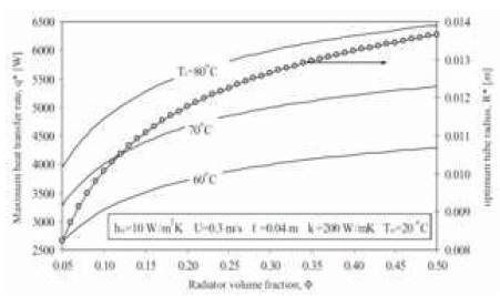
Figure 14. The Effect of Performance Parameters
The CFD simulation was carried out for helical tubes with two different pitches of 15 mm of 20 mm and varying the mass flow rates like 2.3, 2.0, 1.0, 0.5 kg/sec [4]. From the analysis it was found that, helical tubes with 15 mm pitch has more heat dissipation rate than 20 mm and mass flow rate of 0.5 kg/sec shown the maximum temperature drop and minimum pressure drop. The comparison between different mass flow rates in 15 mm pitch of helical tube using ethylene glycol was presented in Figure 15.
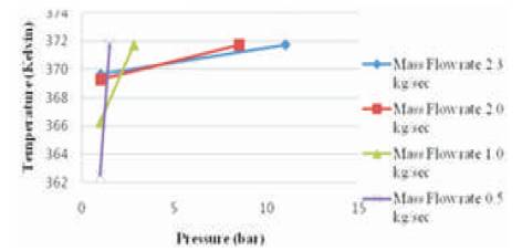
Figure 15. Comparison between Mass Flow Rates
The effect of tube pitch was studied by CFD simulations and found that by varying the pitch of the tube, the heat transfer rate varied [22]. The optimum value has been selected as 12 mm for that particular geometry.
The heat from the liquid was removed by the air surrounded by a mechanism called natural or forced convection through the device called fan [30]. The radiator fan was used to drag the cool air from the atmosphere to pass through the core and louvered fins for surface heat transfer. CFD analysis has been conducted to study the flow of air and interruption of flow by the hub obstruction thus forming unwanted reverse flow regions.
Nowadays, fan design was opted with bigger hub diameter for slim line radiator. Figure 16 represents the flow velocity vectors between and across the blades. It was observed that high flow regions are formed around the outer diameters, whereas low reverse flow in the centre behind the fan hub. Numerical and experimental investigations were performed to study the effect of centrifugal fan parameters such as number of fan blades, outlet angle, and diameter ratio to obtain the better performance [26]. From the investigations it was concluded that, forward curved fan with higher mass flow rates has negligible effect on fuel consumption of vehicle than the backward fan with lower flow rates. Flow coefficient and power coefficient increases by increasing the number of blades and thus increases the efficiency due to better flow guidance and reduced losses. Figure 17 shows the comparison of performance characteristics of fan with 12 and 22 blades running at 4000 rpm. CFD simulation was performed for predicting the flow distribution for right and left oriented fan blade and the results were compared against theoretical and experimental data [17]. Pressure contours, velocity vectors, and path lines were presented in the Figure 18 and revealed the study that a left oriented fan blade performed better in counter clockwise rotation and a right oriented fan blade in clockwise rotation.
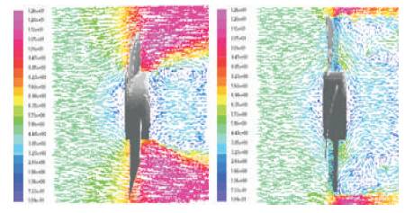
Figure 16. Velocity Vectors of Fan Blades
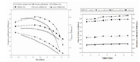
Figure 17. Comparison of Performance Characteristics
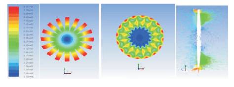
Figure 18. Velocity, Pressure, Flow Lines of Fan Blade
CFD analysis was performed to the fan by varying the number of blades [11]. Optimal number of fan blades was considered as 11 and good practical solutions can be obtained between 5 to 12 blades for designing an efficient and low cost radiator fan. Design and CFD analysis of the fan was performed to obtain the critical information such as efficiency, flow uniformity at the exit, circulation zones, potential cavity location, and noise generation [13] . Contours of static pressure at inlet and outlet are studied. Fan blade angle plays the main role in producing required flow rate. A wavy fin type model was analysed with SiC + water nanofluid as coolant for enhancing the heat transfer rate and reducing the size & weight of the automobile car radiator [8]. CFX analysis was done to the predicted flow behavior and temperature distribution of a wavy fin tube with nanofluids [14]. The cooling capacity can be increased by increasing the air and coolant mass flow rate, coolant inlet temperature, and pressure drop.
The thermal efficiency of radiator can be increased by using nanofluids instead of water [3,6]. Nanofluids are mixed with base fluids such as water, ethylene, and ethylene glycol. CuO, alumina, titanium dioxide, carbon, silica, copper, silver dispersed into the carrier liquid enhances the heat transfer. By using nanofluids, heat transfer rate can be increased by 14% than the water coolants. It helps to design compact and light heat exchangers with same heat transfer capacity. A detailed parametric study on various parameters like coolant mass flow rate, coolant inlet temperature and their behavior were studied by a test setup, and compared for various coolants such as water and other mixtures of water like propylene glycol, ethylene glycol, etc., [27].
Figure 19 shows the schematic diagram of the cooling tower system. It is an evaporative heat exchanger used as cooling medium for condensers.
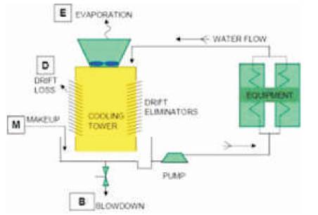
Figure 19. Schematic of Cooling Tower
The heat is transferred from hot water to cool air by direct contact produced by opposed flow. Hot water is sprayed through nozzles from top of the tower and outside air enters from bottom. The two most important performance parameters of cooling tower are evaporation loss and effectiveness [1]. Analytical and experimental study of various parameters related to cooling tower performance was validated using empirical relations and carrier equations [38]. The engineering model was formulated for both counter flow and cross flow cooling towers. The effectiveness of heat exchanger was developed by using the methods of Merkel and Brawn and fundamental laws of mass and energy balance. Coefficients of the model were determined by nonlinear square fitting method. The factors that affect the cooling tower performance were outdoor air flow rate, interior problems of cooling tower, and measurement errors [31]. Experimental and comparative study on tower characteristics for two different types of packing, i.e., vertical corrugated packing, and horizontal corrugated packing was performed. Figure 20 shows the schematic arrangements of two different packings and proved that the efficiency of vertical corrugated packing was higher than the horizontal one.
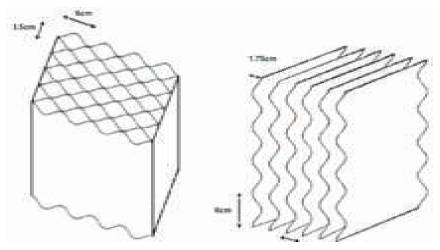
Figure 20. Horizontal and Vertical Corrugated Packing
HCP caused lower water loss with reasonable efficiency. 3 dimensional analysis was carried out to study fluid flow heat transfer and mass transfer for an open type forced draft counter flow water cooling tower [29]. The performance of cooling tower with different oriented mesh packing was analysed [25]. Compared with vertical and horizontal oriented mesh packing, the vertical one performed better than horizontal.
Figure 21 shows the horizontal and vertical oriented wire mesh packing [24]. The mass transferring coefficient of a cross flow tower was analysed and experimentally found that by increasing the mass transferring coefficient, the tower height can be decreased [15]. The effect of wet bulb temperature of the counter flow cooling tower was analysed using thermo-hydraulic per formance optimization analysis. It was studied that wet bulb temperature influence more on the NTU and effectiveness of the tower. The performance can be improved by increasing the water temperature and water mass flow rate. The comparisons of effectiveness for different L/G are shown in Figure 22.
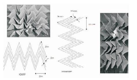
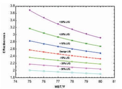
Figure 22. Effectiveness of Different L/G
The study of design characteristics and different types of losses generated in cooling tower were carried and found that the tower performance can be increased by increasing the air mass ratio [21]. Theoretical analysis of heat and mass balance was presented and studied that the evaporative tower cooling efficiency is 5% less than once-through cooling [19]. The overall energy efficiency can be improved by increasing the cooling tower efficiency due to low cost improvement. The effect of corrugated and grid shape of packing in air-water cooling tower has been investigated [20]. The characteristics such as overall volumetric mass transfer coefficient, volumetric mass transfer coefficient, volumetric heat transfer coefficient in gas phase and liquid phase and studied by varying the water flow rates and water temperature, longitudinal and transverse temperature profiles are simulated and compared with the experimental model correlated by lease square method. The effect of air and water flow rate on the performance of the forced draft counter flow cooling tower by conducting numerical and experimental model was investigated [9]. Comparison study between wire mesh with small square holes and expanded wire mesh with diamond holes configuration was carried out and found that latter one has performed better than the former one. The optimal water distribution across the cooling tower was analysed by varying the amount of water to suit the particular air flow conditions [12]. The increased efficiency can be obtained with decrease in entropy generation and energy loss. The CFD analysis of forced draft cooling tower was studied by varying the air inlet parameters with different air inlet angles and by attaching a nozzle in its air inlet path [6]. The air inlet angles considered were horizontal, vertical, combined horizontal and vertical and vertical inclination and the temperature contours were analysed. Compared to all the study it was found that, air inlet pipe with zero and 30 angles performed effectively and can be implemented for small scale industries. An experimental model was created to analyse the performance of cooling tower and found the best way of fan power utilisation that affects the energy cost of tower operation[5]. Figure 23 shows the FEM model of V- shaped Raker column.
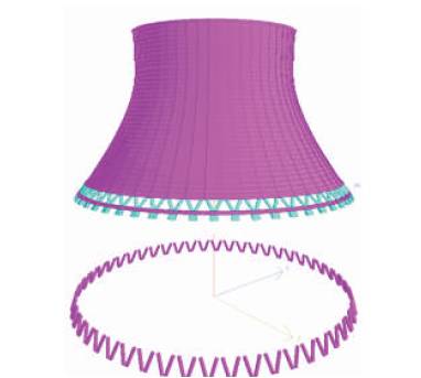
Figure 23. FEM model of V- shaped Raker column
The various performance and geometrical parameters that affect the heat transfer rate are studied. From the literature survey it has been observed that, compared to all the heat exchangers, the radiator is found to be compact, efficient, and has high transfer rate. CFD is the best tool used to analyse the flow of fluids, heat transfer, and temperature and pressure distribution for any design easily.