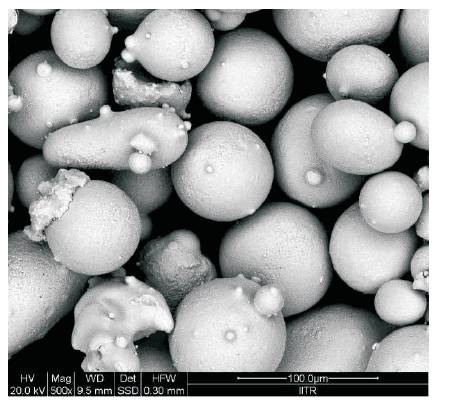
Figure 1. SEM Image of Ni Powder
In the present work, Ni based powder was deposited on stainless steel substrate using a low velocity flame spray technique. The coating of thickness 300 μm was developed using a neutral oxy-acetylene flame. To enhance the microstructure and wear resistance, the coated specimens were heat treated and cooled using various cooling strategies, such as, air, water, and furnace cooling. The microstructure of the as-sprayed and heat treated specimens were studied using SEM. Some unmelted particles and pores were also present in the as-sprayed specimen. The watercooled specimen exhibits equiaxed structure, while the furnace cooled coating demonstrates a coarse structure. The microhardness of the specimens was evaluated using a Vicker's microhardness tester. The water-cooled specimen exhibits highest hardness and wear resistance.
In industries, there is a need of the components with increased life span as well as high performance. Wear cause loss in performance in the tribological components. Thermal spray coatings are widely used to combat wear in many industrial components such as hydro turbines, sliding contacts, etc. Thermal spray coating is a technique of deposition of coating materials for diverse application. The coatings are done to enhance the wear resistance and corrosion. It works on the principle of melting the feedstock material, it may be wire or powder, then to accelerate the molten metal to strike on the substrate with impact followed by rapid cooling gives a build-up coating. Almost any type of material can be coated on substrate with wide range of thickness [1, 6]. There are many varients of thermal spray coatings such as HVOF, TBC, Flame sprayed, and Ni based coatings.
In thermal spray coating, feedstock material is introduced in semi-molten state at low velocity with hot gas jet obtained by combustion of fuel gas & oxygen. After this, semi-molten material with kinetic energy is capable of forming thick dense coating. It is most widely used for depositing metals, ceramics & cermets (ceramics + metals) [2,3]. High velocity thermal spray coatings provide more dense and homogeneous coatings compared to other thermal sprayed coatings because of higher kinetic energy of the feedstock material and low spray temperatures [4]. Cermet coatings or carbide coatings deposited with nanoparticles improve wear resistance properties compared to conventional powder materials [5- 13]. Thermal Barrier Coatings (TBC) are used where wear, high temperature, and corrosion resistance surfaces are required, for example in turbine components and inner walls of IC engines cylinders, etc [4]. Whereas other thermal spray technique coating provides higher porosity & lesser bonding strength as compared to low velocity flame sprayed coatings [3].
Ni based Thermal Barrier Coatings (TBCs) coatings are most widely used in industries now-a-days especially for turbine components, internal combustion engine cylinders, and in a number of applications where wear, temperature as well as corrosion resistant surfaces are required [14-16]. Ni based alloys with carbides coatings are most widely used for typical applications for a boiler tube as well as in continuous caster mould [17-19]. Ni based self-fluxing alloys are also popular where corrosion resistant with moderate temperature are required [20-22].
Heat treatment is a process in which material is heated to a specified temperature for improving its properties according to the requirement of application. Heat treatment causes the microstructure of the material to change as a function of the heating and cooling cycle during the heat treatment. The cooling cycle influences the microstructure of the material to a considerable extent. For example, if the material is suddenly cooled, it will develop a finer grain structure. If cooling is done slowly, then coarser grain structure will be formed. Finer the grain structure better exhibits improved mechanical as well as tribological properties.
In the present work, Ni based powder coating was developed using low velocity flame spraying technique. The coated samples were heat treated at a specified temperature, i.e. 300 oC for 60 minutes and were cooled using different cooling strategies. Characterization of the differently cooled samples was done using electron microscopy. Microhardness of the differently cooled specimens was assessed using a Vicker's microhardness tester. Study of abrasive wear performance of these samples have been done using pin on disc tribometer. Wear resistance was quantified in terms of cumulative weight loss. The influence of different cooling strategies on wear resistance has been illustrated and discussed in the present work.
Nickel (Ni) based powder was used to coat the Stainless Steel (SS-304) coupons using a flame spraying equipment. The Ni based powder exhibited a spherical morphology with an average particle size of 50-100 μm (Figure 1). The SS-304 rolled plates were machined to a size of 25 × 25 × 5 mm3 . The substrates were cleaned thoroughly with acetone after that they were grit blasted using grit blasting machine with alumina particles of 150 μm having pressure up to 5 bar to achieve a surface roughness of 5 μm for proper mechanical anchoring with coating layer. The elemental composition of the Ni-based powder was determined using an Energy Dispersive Spectroscopy (EDS, Make: Oxford X-max). An optical emission spectrometer was used to determine the elemental composition of the SS-304 substrate. The elemental composition of the powder and substrate are presented in Table 1.
Figure 1. SEM Image of Ni Powder
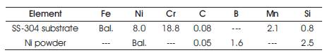
Table 1. Elemental Composition (wt %) of SS- 304 and Ni Powder
In this work, the coating powder was deposited using Low Velocity Oxy-Fuel Flame (LVOF) technique on the substrate with 300 μm thickness. The coating was done by using LVOF 5PM II thermal spray gun (Make: MC Thermal Spray Equipment, Jodhpur). The oxygen and acetylene flow rate were maintained at 30 l/min, while the powder feed rate was 15 g/min. After the coating was done, the samples were heat treated using a muffle furnace (make: Heraeus Electronics, model: Heraeus CD-6450) at 300 oC for 60 minutes. The heat-treated samples were then cooled using various cooling methods like air cooling, furnace cooling, and water quenching. In water cooling, heat treated samples were allowed to cool in water at 25 oC. In air cooling, the samples after heat treatment were allowed to cool at room temperature. In furnace cooling, samples were left in the furnace for cooling.
The coatings were characterized through various techniques to evaluate the microstructure, microhardness, coefficient of friction, and abrasive wear mechanisms. Before characterization, the coated samples were cleaned with acetone in an ultrasonic bath and were sectioned across the thickness of coating using low speed diamond saw (Make: Chennai Metco, India, Model: BAINCUT LSS). The sectioned samples were polished using emery papers of different grit sizes varying from 220-2000 and with 1 μm diamond paste on cloth wheel to attain mirror finish. The microstructure of the coatings was observed using a Field Emission Scanning Electron Microscope (FE-SEM, Make: FEI, Model: Quanta 200 FEG). The microhardness of coatings was evaluated using a Vicker's microhardness tester (Make: Chennai Metco) at a load of 50 g applied for 10 s. The indentions were done across the cross section of the coatings. An average of ten readings were considered.
The abrasive wear testing of the Ni coatings was carried out using pin-on-disc tribometer (Make: Ducom). A schematic of the abrasive wear testing setup is shown in Figure 2. Specimens were fixed in a fixture and exposed to the abrasive paper (Make: 3M) of grit size 600 during testing. Various testing parameters used are shown in Table 2. After the completion of test, samples were ultrasonicated in an acetone bath and hot dried before weight loss measurement. The weight loss of the worn samples was measured using an electronic weighing balance (Make: Citizen) having an accuracy of ±0.01mg. The worn surfaces were further analyzed using SEM. Coefficient of friction of coated samples was calculated by using the relation, μ=F1 /FN , where F1 is the tangential force in N and FN is the normal force (10 N). The parametric details of the abrasive wear test are presented in Table 2.
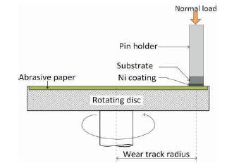
Figure 2. Schematic of Abrasive Wear Testing Setup
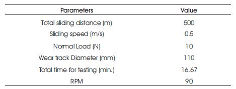
Table 2. Testing Parameters
The typical SEM micrograph of the coating is shown in Figure 3. A coating thickness of 300 μm can be observed. The coating is well anchored with the substrate. No discontinuity along the interface is visible. The coating exhibits certain dark spots, which are the microporosities present in the coatings. The microporosities are inherent with the coating process. The coating was heat treated and cooled using different cooling strategies to enhance the wear resistance of the coating. The cooling was carried out using three different media, water, air, and furnace cooling.
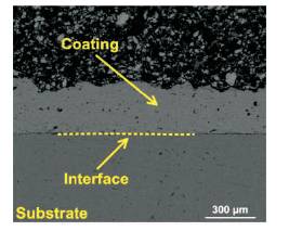
Figure 3. SEM Image of Cross-Section of Ni Coating
The SEM micrograph of the as-sprayed specimen shows presence of unmelted particles along with porosity (Figure 4 (a). The presence of unmelted particles will tend to reduce the wear performance of the coatings. By heat treatment and cooling, the structure of the coating layer can be altered. The air-cooled specimen reveals the presence of relatively fine structure. This could be attributed to the faster cooling rate in air after heat treatment. Finer structure could enhance the hardness and wear resistance of the air-cooled specimens. The water-cooled specimens have equiaxed structure which demonstrates the maximum hardness and wear resistance. The furnace cooling has slow cooling rate, therefore the specimen has the coarse grains as shown in Figure 4(d).
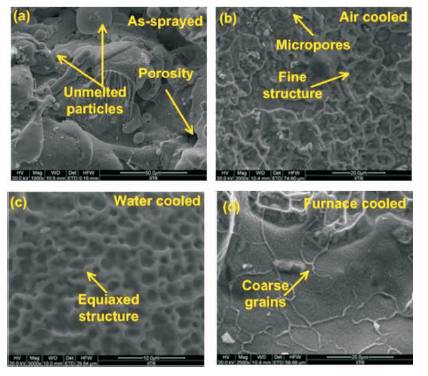
Figure 4. SEM Images of Specimens Cooled using Various Strategies
The observed microhardness distribution across the coating cross-section is illustrated in Figure 5. The variation in microhardness is due to the variations in cooling strategies of coated samples. The average microhardness of the as-sprayed samples was 556 HV. The water-cooled sample exhibits maximum hardness due to formation of equiaxed structure. The hardness of the water-cooled specimen increases by 12% (623 HV). The hardness of the air-cooled specimen was only 3% higher (573 HV) compared to the as-sprayed specimen. The coarse grains in the furnace cooled specimen reduce the hardness of the specimens. The hardness in the furnace cooled specimens was reduced by 4% (533 HV). A maximum hardness is achieved in water cooled samples compared to furnace and air cooled because of refinement of the microstructure. The hardness of coated samples varies according to the cooling strategies used. The hardness in coating is due to the formation of equiaxed structure during cooling as already discussed in microstructural examination in section 2.1.
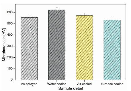
Figure 5. Microhardness Distribution for Different Samples
The wear behaviour of the heat-treated specimens was examined after using a pin-on-disc setup. The wear resistance of the specimens was evaluated in terms of cumulative weight loss. The cumulative weight loss of the specimens is presented in Figure 6. It is observed that hardness values influenced the sliding wear behaviour of the samples as per the Archard's law. The maximum weight loss was observed in case of furnace cooled specimen attributed to the coarse grains (Figure 4 (d)). The coarse grain reduces the hardness of the coating layer (Figure 5). The weight loss was increased by approximately 20% for the furnace cooled specimen. The water-cooled specimen with equiaxed structure and maximum hardness shows the minimum weight loss (Figure 6). The as-sprayed and air cooled specimens show wear loss intermediate to the water cooled and furnace cooled specimens.
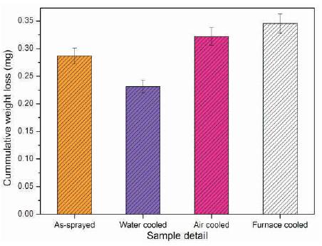
Figure 6. Cumulative Weight Loss for Different Samples
It can be observed that the wear tracks formed due to abrasion is less in case of water quenching, higher in case of air cooled and maximum in case of furnace cooling. Water quenched samples will have finer grain structure, whereas furnace cooled samples will have coarser grain structure which are more prone to wear. Due to this, water quenched samples will suffer less wear followed by air cooling and increasing order from water, air and furnace cooled. Deeper and wider groove marks are indicative higher mass loss as shown in Figures 7(b), and (d).
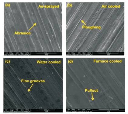
Figure 7. SEM Images of Worn Surfaces of Specimens Cooled using Various Strategies
Figure 7 shows the SEM images of worn out surfaces after abrasive wear test. As discussed earlier, coating with higher hardness will exhibit higher wear resistance hence lower mass loss. Abrasion, ploughing, and grooving were the main wear mechanisms in the samples. However, the water cooled specimens exhibit finer groove marks as indicated in Figure 7 (c). Finer groove marks are an indicative of higher wear resistance. Water quenched samples have higher wear resistance as compared to air and furnace cooled coatings. It can be seen clearly and understood that the wear tracks formed due to abrasion is less in case of water quenching, higher in case of air cooled and maximum in case of furnace cooling. Water quenched samples have finer grain structure, whereas furnace cooled samples have coarser grain structure which are more prone to wear. Due to this, water quenched samples suffer less wear followed by air cooling and then furnace cooling. Penetration of wear is in increasing order from as water, air and furnace cooled. Deeper and wider groove marks are indicative higher mass loss as shown in Figures 7(b) and (d).
The Ni-based coatings were developed on stainless steel substrate using flame spray technique. The following conclusions are drawn from the present study: