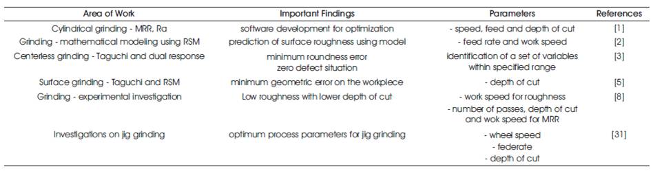
Table 1. A Summary of Important Studies Among Recent Developments in Grinding and Allied Processes, with a Focus on Jig Grinding
Jig grinding is a process practically used by tool and die makers in the creation of jigs or mating holes and pegs on dies. The abrasives normally used in jig grinding are divided into Natural Abrasives and Artificial Abrasives. Artificial Abrasives are preferred in manufacturing of grinding wheels in jig grinding, because of their uniformity and purity. In this paper, a brief review of the analysis of jig grinding process considering various research trends is presented. The areas highlighted are: optimization, selection of abrasives, selection of processing conditions and practical considerations. The optimization of parameters in jig grinding process is important to maximize productivity and to improve quality. The abrasives of hard jig grinding wheels get blunt quickly so these are recommended to grind the workpiece of low hardness and soft grinding wheels are recommended for hard material workpieces. The jig grinding is also classified into rough grinding and precision grinding, based on the processing conditions. The jig grinding process is also adapted for a variety of practical applications and different materials.
Demand are being placed based on practical applications; on the automobile, aerospace, and medical component industries to produce stronger, lighter, precision parts [1]. This in return is driving improvement and development to be made in the machining processes that are used to produce these parts. Conventional machining processes are being pushed to their limits of performance and productivity [2, 3]. Many non-traditional processes, such as electrical-discharge machining, electro-chemical machining, and ultrasonic machining are being used to meet the industries’ demands. Non-traditional processes do not rely on contact between the tool and the workpiece to remove material in the form of chips [4, 10]. In many cases, these processes use a tool that is softer than the workpiece. Jig grinding is an essential process for final machining of the components requiring smooth surfaces and precise tolerances [5, 23]. As compared with other machining processes, grinding is a costly operation that should be utilized under optimal conditions. Although widely used in industry, grinding remains perhaps the least understood of all machining processes [6-9]. Besides that, surface topography also is of great importance in specifying the function of a surface. A significant proportion of component failure starts at the surface due to either an isolated manufacturing discontinuity or gradual deterioration of the surface quality. Typically are the laps and folds which cause fatigue failures and of the latter is the grinding damage due to the use of a worn wheel resulting in stress corrosion and fatigue failure [10, 11]. The most important parameter describing surface integrity is surface roughness. In the manufacturing industry, surface must be within certain limits of roughness. Therefore, measuring surface roughness is vital to quality control of machining workpiece [12,13-15]. Grinding may be classified into two groups as rough or non-precision grinding and precision grinding [16]. Snagging and off hand grinding are the common forms of the rough grinding where the metal is removed without regard to accuracy [17,18]. In precision grinding, according to the type of surface to be grounded, it is classified into external or internal grinding, surface and cylindrical grinding. The achievement of desirable value is a very critical process as the parts have already passed through many machining stages. In order to maintain quality, the variables that affect the grinding process must be defined experimentally and monitored in the process [19-22].
The basic target of the grinding process is to achieve the required shape, size and surface topography of the finished product in a most economical way. In modern manufacturing and assemblies, high dimensional accuracy and fine surface finish play an important role [23]. The improvement in surface finish on the workpieces lead to higher corrosion resistance, fatigue strength and reduced power loss due to friction. The major operating input parameters that influence the output responses, metal removal rate, surface roughness, surface damage, and tool wear, etc. are (i) wheel parameters: abrasives, grain size, grade, structure, binder, shape and dimension, etc. (ii) Workpiece parameters: fracture mode, mechanical properties and chemical composition, etc. (iii) Process parameters: work speed, depth of cut, feed rate, dressing condition, etc. (iv) machine parameters: static and dynamic Characteristics, spindle system, table system, etc. [24]. Most of the papers take into account the following input processes parameters namely wheel speed, feed rate and depth of cut. Some of the research groups have used their knowledge on grinding process that can be utilized to predict the grinding behavior to achieve optimal operating processes parameters [25].
The knowledge is mainly in the form of physical and empirical models which describe various aspects of grinding process. A software package has been developed which integrates these various models to simulate what happens during the Jig grinding processes [26]. In the work, predictions from this simulation are further analyzed by calibration with actual data. The variables considered involve several factors such as depth of cut, wheel speed, feed rate, grit size, type of abrasive, chemical composition of wheel, etc. The main objective in most of the machining processes is to maximize the Metal Removal Rate (MRR) and to minimize the Surface Roughness (Ra). In order to optimize these values, Taguchi method, ANOVA and regression analysis are used. The most important parameter describing surface integrity is surface roughness. In the manufacturing industry today, surface must be within certain limits of roughness [27]. Therefore, measuring surface roughness is vital for quality control of the machining workpiece. Surface roughness is also a great concern in manufacturing industrial environment. Parts such as automobile, aerospace, and medical component need high precision in surface finish. Therefore, there are problems in attempting to get high quality surface finish of the product [28, 29].
Besides that, optimization of grinding parameter is usually a difficult work, where the following aspects are required such as, knowledge of machining and specification of machining tools capabilities. The optimization parameters of machining are important especially in maximization of production rate, reduce cost and production rate. Optimization parameters of machine to make a good quality for surface roughness are of great concern in the manufacturing environments, where economic of machining operation plays a key role in competitiveness in the market [30]. Parameters that must be identified for Surface Roughness and Material Removal Rate [31] are wheel speed, feed rate and depth of cut. Other parameters of Jig grinding machine are constant. Therefore, in the following sections, a brief review of the practical aspects of jig grinding process has been done in detail. The factors considered for the review are: jig grinding equipments, jig grinding wheels, jig grinding processing conditions and jig grinding operation strategies.
M. Janardhan and Gopala Krishna [1] proposed that in cylindrical grinding, Metal Removal Rate and surface finish are the important responses. Experiments were conducted on CNC cylindrical grinding machine using EN8 material (BHN-30-35) and they found that the feed rate played a vital role on responses of surface roughness and the metal removal rate than other process parameters. In that work, the following input processes parameters, namely: work speed, feed rate and depth of cut are used. The main objective of the paper was to show how our knowledge on grinding process can be utilized to predict the grinding behavior and achieve optimal operating processes parameters. A software package was developed which integrates these various models to simulate what happens during cylindrical grinding processes. Predictions from this simulation are further analyzed by calibration with actual data. Furthermore, several variables such as depth of cut, work speed, feed rate, grit size, type of abrasive, chemical composition of wheel, etc. are considered. It is known that, any machining process is to maximize the Metal Removal Rate (MRR) and to minimize the Surface Roughness (Ra). In order to optimize these values, Taguchi method, ANOVA and regression analysis are used. The concept of ANOVA and S/N ratio is used to determine the effect and influence of process parameters namely work speed, feed rate and depth of cut studied on output responses, and found that the developed model is significant. MINITAB16 software is used for the analysis of response graphs of average values and S/N ratios. From the Pareto analysis, it is evident that the feed rate played a vital role on output responses of Surface Roughness and Metal Removal Rate (MRR) than other process parameters. The model predicted in the work was useful for selecting the right set of process parameters variables for optimal value of the MRR and Surface roughness.
In another investigation, M.A. Kamely et al. [2] have developed a mathematical model of the surface roughness by using Response Surface Methodology (RSM) in grinding of AISI D2 cold work tool steels. Analysis of variance (ANOVA) was used to check the validity of the model. Low and high value for work speed and feed rate are decided from the design of experiment. The influences of all machining parameters on surface roughness were analyzed based on the developed mathematical model. The developed prediction equation by these authors showed that both the feed rate and work speed are the most important factors influencing the surface roughness. The surface roughness was found to be the lowered with the usage of low feed rate and work speed. Accuracy of the best model was proved with the testing data. From the analysis, it was found that feed rate affect the most on the surface roughness. The surface roughness changes drastically with the increasing feed rate, regardless with the change of work speed. Feed rate and work speed are very crucial factors that need to be controlled and chosen carefully. An actual modeling approach using Response Surface Methodology for prediction of surface roughness in grinding has been developed. The developed models were evaluated for their prediction capability with measured values. The predicted values were found to be close to the measured values. The proposed models can be used effectively to predict the surface roughness in grinding process.
M.N. Dhavlikar et al. [3] have done a project on Combined Taguchi and dual response method for optimization of a centerless operation. In their work, a successful application of combined Taguchi and dual response methodology to determine robust condition for minimization of out of roundness error of workpieces for center less grinding operation was determined. From the confirmation runs, it was observed that this approach led to a successful identification of the optimum process parameter values. The application of combined Taguchi and dual response methodology has resulted in a solution, which has led to almost zero defect situation for the centerless grinding process. The concept of S/N ratio from Taguchi methodology was used to measure the variance of out of roundness error. The dual response methodology was used to formulate an objective function to obtain optimum condition for the process. Regression analysis was done on the experimental runs to obtain equations for S/N ratio and an average out of roundness error. These equations were then used in the objective function formulated using dual response methodology. The primary objective was to minimize the S/N ratio while keeping the out of roundness error below 5 mm. Monte Carlo simulation procedure was used to determine the optimum condition by sequentially narrowing down the search range of the variables around the best solution obtained at every run.
The investigation done by S. Shaji and Radhakrishnan [4] revealed that the process parameters such as speed, feed, infeed and mode of dressing as influential factors, on the force components and surface finish were developed based on Taguchi's experimental design methods. Taguchi's tools such as orthogonal array, signal-to-noise ratio, and factor effect analysis, ANOVA, etc. have been used for this purpose and an optimal condition has been found out. The results have been compared with the results obtained in the conventional coolant grinding. It has been observed that, with the graphite application, the tangential force and surface roughness are lower and the normal force is higher compared to those in the conventional grinding.
Jae-Seob Kwak [5] applied Taguchi and response surface methodologies for geometric error in surface grinding process. The effect of grinding parameters on the geometric error was evaluated and optimum grinding conditions for minimizing the geometric error were determined. A second-order response model for the geometric error was developed and the utilization of the response surface model was evaluated with constraints of the surface roughness and the material removal rate. Confirmation experiments were conducted at an optimal condition and selected two conditions for observing accuracy of the developed response surface model. The effect of grinding parameters on the geometric error was evaluated with help from the Taguchi method. The depth of cut was a dominant parameter for geometric error and the next was the grain size. Optimal grinding conditions to minimize the geometric error were determined. A secondorder response surface model for the geometric error was developed from the observed data. The utilization of the response surface model was evaluated to select proper grinding conditions with constraints of the Surface Roughness and the Material Removal Rate. Confirmation experiments of the response surface model were conducted at an optimal condition and two selected conditions. It was shown that the developed response surface model was very useful for predicting the geometric error.
In another work, Suleyman Neseli et al. [6] applied combined Response Surface Methodology (RSM) and Taguchi Methodology (TM) to determine optimum parameters for minimum Surface Roughness (Ra) and Vibration (Vb) in external cylindrical grinding. First, an experiment was conducted in a CNC cylindrical grinding machine. The TM using L27 orthogonal array was applied to the design of the experiment. The three input parameters were workpiece revolution, feed rate and depth of cut; the outputs were vibrations and surface roughness. Second, to minimize wheel vibration and surface roughness, two optimized models were developed using computer-aided single-objective optimization. The experimental and statistical results revealed that the most significant grinding parameter for surface roughness and vibration is workpiece revolution followed by the depth of cut. The predicted values and measured values were fairly close, which indicates that the developed models can be effectively used to predict surface roughness and vibration in the grinding. This paper applies the Taguchi and response surface methodology from the point of view of external grinding. The concept of S/N ratio from Taguchi methodology was used to measure the variance of wheel vibration and surface roughness. The response surface methodology was used to formulate an objective function and non-linear optimization to obtain the optimum condition for the process. By the experimental and statistical results, the conclusions were as follows. The statistical analysis by using Taguchi and response surface methodologies has demonstrated that the depth of cut and workpiece revolution were the dominant parameters among the three controllable factors that influence the wheel vibration and surface roughness in the external grinding operation during AISI 8620 steel machining.
Kundan Kumar et al. [7] proposed Optimal material removal and effect of process parameters for the cylindrical grinding machine by Taguchi method. This research outlines the Taguchi's Parameter Design Approach, which has applied to optimize machining parameters in Cylindrical Grinding Process. The grinding parameters evaluated are cutting speed and depth of cut. An orthogonal array, Signal-to-Noise (S/N) ratio and Analysis of Variance (ANOVA) are employed to analyze the effect of these grinding parameters. An orthogonal array has been used to plan the experiments. The raw data analysis and signal-to-noise ratio analysis have employed to analyze the influence of grinding parameters on material removal rate during the grinding process. The purpose of the Analysis of Variance (ANOVA) is to investigate which design parameters significantly affect the quality characteristic. This procedure eliminates the need for repeated experiments, saves time and conserves the material as opposed by the conventional procedure. Experimental results are provided to confirm the effectiveness of this approach.
Jagtap [8] proposed that for Surface Roughness (Ra), the Work Speed (Nw) was the most influencing factor for AISI 1040 work material followed by grinding wheel speed, number of passes and depth of cut. So, to achieve the minimum surface roughness of AISI 1040 steel, they employed low depth of cut. For Metal Removal Rate (MRR), for the work material AISI 1040, the most influencing factor was Number of Passes (Np), second being Depth of Cut (Dc) followed by grinding wheel speed and Work Speed (Nw). So, to achieve the maximum metal removal rate of AISI 1040 steel, employ higher depth of cut, moderate work speed with minimum number of passes of 03 and high grinding wheel speed. The optimum grinding conditions which would minimize surface roughness and maximize metal removal rate when grinding AISI 1040 steel were obtained. Empirical models were developed using the design of the experiments by Taguchi L9 Orthogonal Array and the adequacy of the developed model is tested with ANOVA. The developed model can be used by different manufacturing firms to select appropriate combination of machining parameters to achieve an optimal Metal Removal Rate (MRR) and Surface Roughness (Ra). The input parameters considered are: wheel speed, work speed, number of passes and depth of cut and the responses are Metal Removal Rate (MRR) and Surface Roughness (Ra). The results were further validated by conducting confirmation experiments.
Alao Abdur-Rasheed and Mohamed Konneh [9] aimed at Optimization of Precision Grinding Parameters of Silicon for Surface Roughness Based on Taguchi Method. The investigation was on the effect and optimization of grinding parameters using Taguchi optimization technique during precision grinding of silicon. In this work, experimental studies were conducted under varying depths of cut, feed rates and spindle speeds. An Orthogonal Array (OA), Signalto- Noise (S/N) ratio and the Analysis of Variance (ANOVA) were employed to find the minimum surface roughness value and to analyze the effect of the grinding parameters on the surface roughness. Confirmation tests were carried out in order to illustrate the effectiveness of the Taguchi method. The results obtained showed that feed rate mostly affected the surface roughness. The predicted roughness (Ra) of 34 nm was in agreement with the confirmation tests. Massive ductile streaked surface was also found corresponding to the minimal surface finish determined from the optimal levels. In most of the investigations, statistically designed experiments based on Taguchi method were performed using L9 (34) OA to analyze the surface roughness. Conceptual S/N ratio and ANOVA approaches drew similar results. Statistical results at 95% confidence level showed that the feed rate, spindle speed and depth of cut affect Surface Roughness (Ra) by 37.878%, 34.658% and 20.89% respectively. The minimum predicted surface roughness (Ra) was evaluated as 0.034 μm by Taguchi optimization method and the roughness (Ra) from the confirmation experiments was 0.030 μm. It can be observed that the difference between the value of the minimum and the actual Surface Roughness (Ra) is about 12%. An analysis of the confirmation experiments for surface roughness has showed that Taguchi parameter design can successfully optimize the precision grinding parameters for silicon at depth of cut, 12. 5 μm, feed rate, 6.25 mm/min and spindle speed 70,000 rpm.
In another work done by Mustafa Kemal Külekcý [10], analysis of process parameters for a surface Grinding process based on the Taguchi method was carried out. In this study, the wheel speed (V), the rate of feed (F) and the depth of cut (D) were selected as variable parameters. Other process parameters were fixed. In this, an application and adaptation of the Taguchi optimization and quality-control method were established for the optimization of the surface roughness in a grinding process. The Taguchi method provides a systematic and efficient methodology with fewer experiments and trials. The experimental results obtained in this study showed that the depth of cut and the wheel speed have significant effects on the surface roughness. The rate of feed has a lower effect on the surface roughness. The contribution order of the grinding parameters including the depth of cut, the wheel speed and the rate of feed is 50 %, 40 % and 10 %, respectively. A change made to all the grinding parameters significantly changes the surface roughness. The optimum grinding parameter combination for the AISI 1040 steel includes the wheel speed (V) of 1500 r/min and the depth of cut (D) of 0.05 mm.
Deepak Pal et al. [11] investigated the optimization of grinding parameters for Minimum surface roughness by Taguchi Parametric Optimization Technique. In their work, experiments were conducted on universal tool and cutter grinding machine with L9 Orthogonal array with input machining variables as work speed, grinding wheel grades and hardness of material. The developed model can be used by the different manufacturing firms to select right combination of machining parameters to achieve an optimal Surface Roughness (Ra). The results reveal Surface Roughness (Ra). The results were further confirmed by conducting confirmation experiments. From main effects plotted, it was observed that there is a decrease in the surface roughness as material hardness is increased. The roughness decreases when speed is changed from 100 to 160 rpm and again decreases when speed is changed to 200 rpm, similarly when grinding wheel grain's change from G46 to G60 surface roughness decreases, but as again change to G80 roughness increase considerably. (H2), Larger Wokpiece speed (W3) and Medium Grain's (G2), and then the Surface Roughness is minimum obtained. A summary of this section is presented in Table 1. In section 2, the details of jig grinding equipments are elaborated.
Table 1. A Summary of Important Studies Among Recent Developments in Grinding and Allied Processes, with a Focus on Jig Grinding
A jig grinder [31] is a machine tool used for grinding complex shapes and holes, where the highest degrees of accuracy and finish are required, as in Figure 1. The jig grinder is very similar to a jig borer, in that the table positioning and spindles are very accurate (far more so than a manual milling machine or lathe). It is almost exclusively used by tool and die makers in the creation of jigs or mating holes and pegs on dies. There are usually many peripheral elements to a large jig grinder, including separate hydraulic motors, air compressors, and various cooling systems for both the hydraulic circuit and supplying coolant to the work and machine itself. The machine operates by a high-speed air spindle rotating a grinding bit.
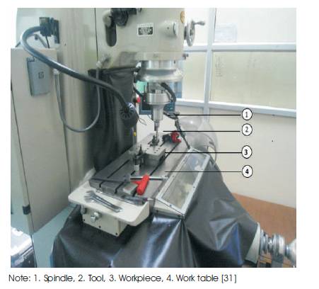
Figure 1. Jig Grinding Experimental Setup
The air spindles are removable and interchangeable to achieve varying surface speeds. Some spindles are fixed speed (60000 rpm), others are adjustable (30000-50000 rpm), and still others are very high speed (175000 rpm). The machines have a standard X-Y table with the notable exception of knee travel. All axes are indexed to .0001" via a Vernier scale on the hand wheels, with higher accuracy available with the use of measuring bars. The machine head has two vertical travels, one rough head adjustment and the other a precise spindle adjustment.
The spindle to which the detachable air spindle mounts also rotates at a variable speed and can typically outfeed .100" while running, again with an accuracy of .0001" on the hand wheel or greater, for very precise hole, peg and surface grinding. A well-kept jig grinder will reliably position work to a higher degree of accuracy than is possible with hand wheels alone. These features are all critical in positioning a hole and peg system, a precise distance from a reference surface or edge. The most important factor on a jig grinder is the dual-spindle configuration. The main spindle is roughly positioned with between 1" or 2" of travel for setup, and then the .100" of outfeed is used during machine operation to out feed into the work. A space bar may be used between the grinder and main spindle, allowing large (9" radius or larger) work to be completed. The main spindle has a wide range of speed to ensure whether proper grinder feed rates are maintained. Figure 2 shows a jig grinding tool. The jig grinding equipment and characteristics detailed in this section has been summarized in Table 2.
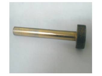
Figure 2. Jig Grinding Tool [31]
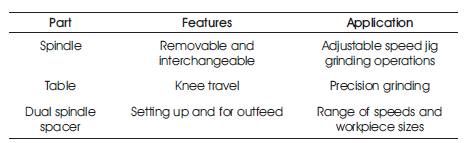
Table 2. A Summary of Jig Grinding Equipment and Characteristics [31]
Grinding wheel is a multipoint cutting tool having abrasive particles bonded together and so forming a structure. The various main elements of a grinding wheel are abrasive; bonds and structure which are described. Generally, abrasive properties like hardness, toughness and resistance to fracture uniformly abrasives are classified into two principal groups :(a) Natural abrasives, and (b) Artificial abrasives, (Figure 3) for classification. There are a few examples of natural abrasives which include sand stone (solid quartz); emery; corundum and diamond.
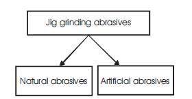
Figure 3. Classification of Jig Grinding Abrasives
Diamond is not recommended to use as abrasive due to its cost in effectiveness. However, diamond dust which is the waste of diamond dressing operation can be used as abrasives. Natural abrasives are being described below. Sand stone is one of the natural abrasives used to make grinding stones. These are relatively soft. These cannot be used for grinding of hard material and at faster speed. Emery is a natural aluminum oxide containing 55 to 65% alumina, rest are iron oxide and impurities. If percentage of aluminum oxide is more, ranging from 75 to 95%, then it is called corundum. It consists impurities as remaining amount. Both emery and corundum are harder than quartz and can have better abrasive action. Normally, natural abrasives are not preferred due to the presence of larger impurities and lack of uniformly in constituents, as both of these things influence the performance of grinding wheel adversely. Main artificial abrasives are silicon carbide and aluminium oxide. Artificial abrasive are preferred in manufacturing of grinding wheels, because of their uniformity and purity. Artificial abrasives are described. Silicon Carbide is also called carborundum. It is manufactured from 56 parts of silica sand, 34 parts of powdered cake, 2 parts of salt, 12 parts of saw dust in a long rectangular electric furnace of resistance type. Sand furnishes silicon, cake furnishes carbon, and saw dust makes the charge porous, salt helps in fusing it. There are two types of silicon carbide abrasive, green grit with approximately 97% silicon carbide and black grit with approximately 95% silicon carbide. It is less harder than diamond and less tough than Aluminum oxide. It is used for grinding of material of low tensile strength like cemented carbide, stone and ceramic, gray cast iron, brass, bronze, aluminum vulcanized rubber, etc. It is prepared by heating mineral bauxite, a hydrated aluminum oxide clay containing silica, iron oxide, titanium oxide mixed with ground coke and iron borings in an arc type electric furnace. Aluminum oxide is tough and fracture resistant. It is preferred for grinding of materials of higher tensile strengths like steel; high carbon and high speed steel and tough bronze. A bond is an adhesive material used to held abrasive partials together; relatively stable that constitutes a grinding wheel. Different types of bonds are: (a) Vitrified bond, (b) Silicate bond, (c) Shellac bond, (d) Resinoid bond, (e) Rubber bond, and (f) Oxychloride bond, (Figure 4) for classification. These bonds are being explained here in brief.
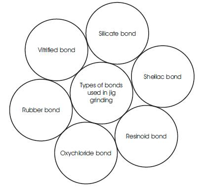
Figure 4. Different Types of Bonds
This bond consists of mixture of clay and water. Clay and abrasives are thoroughly mixed with water to make an uniform mixture. The mixture is moulded to a shape of a grinding wheel and dried up to take it out from mould. Perfectly shaped wheel is heated in a kiln just like brick making. It this way, clay vitrifies and fuses to form porcelain or glass grains. High temperature also does annealing of abrasive. This wheel posses a good strength and porosity to allow high stock removal with coal cutting. Disadvantage of this type of wheel is, it is sensitive for heat, water, oil and acids. Their impact and bending strengths are also low. This bond is denoted by symbol 'V' in specification. Silicate bonds are made by mixing abrasive partials with silicate and soda or water glass. It is moulded to required shape, allowed to dried up and then taken out of mould. The raw moulded wheel is baked in a furnace at more than 200oC for several days. These wheel exhibits water proofing properly so these can be used with coolant. These wheels are denoted by 'S' in their specification. These are prepared by mixing abrasive with shellac, and then moulded by rolling and pressing and then by heating upto 150oC for several hours. This bond exhibits greater elasticity than other bonds with appreciable strength. Grinding wheels having shellac bond are recommended for cool cutting on hardened steel and thin sections, finishing of chilled iron, cast iron, steel rolls, hardened steel cams and aluminium pistons. This bond is denoted by 'E' in specifications. These bonds are prepared by mixing abrasives with synthetic resins like backelite and redmanol and other compounds. Mixture is moulded to a required shape and baked up to 200oC to give a perfect grinding wheel. These wheels have a good grinding capacity at higher speed. These are used for precision grinding of cams, rolls and other objects, where high precision of surface and dimension influence the performance of operation. A resinoid bond is denoted by the letter 'B' Rubber bonded wheels are made by mixing abrasives with pure rubber and sulphur. After that, the mixture is rolled into sheet and the wheels are prepared by punching using die and punch. The wheels are vulcanized by heating then in furnace for short time. Rubber bonded wheels are more resilient and have larger abrasive density. These are used for precision grinding and good surface finish. Rubber bond is also preferred for making thin wheels with good strength and toughness. The associated disadvantage with rubber bond is, these are lesser heat resistant. A rubber wheel bonded wheel is denoted by the letter 'R'. These bonds are processed by mixing abrasives with oxides and chlorides of magnesium. The mixture is moulded and baked in a furnace to give the shape of a grinding wheel. These grinding wheels are used for disc grinding operations. An oxychloride bonded wheel is specified by the letter 'O'. The selection of elements, types and applications of appropriate grinding wheels are shown in Table 3.
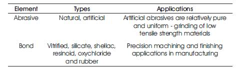
Table 3. A Summary of Jig Grinding Wheel Characteristics and Applications
Normal parameters used in the grinding operation are cutting speed, feed rate and depth of cut. These parameters are described in this section. Cutting speed of a grinding wheel is the relative peripheral speed of the wheel with respect to the workpiece. It is expressed in meter per minute (mpm) or meter per second (mps). The cutting speed of grinding wheel can be calculated as,
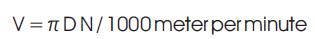
where, D is the diameter of grinding wheel in mm. N is the number of revolution of grinding wheel if N is expressed in terms of number of revolutions per minute, V will be in mpm.
Feed rate is a significant parameter in case of cylindrical grinding and surface grinding. Feed rate is defined as the longitudinal movement of the workpiece relative to axis of grinding wheel per revolution of grinding wheel. Maximum feed rate should be upto 0.9 time of face width of grinding wheel for rough grinding and upto 0.6 times of face width of grinding wheel for finish grinding. Feed cannot be equal to or more than the width of grinding wheel. Feed is used to calculate the total grinding time as given below.
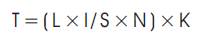
where, T is the grinding time (min), L is the required longitudinal travel in mm, i is the number of passes required to cover whole width, S is the longitudinal feed rate (mm/rev.), N is the rpm and K is the coefficient depending on the specified grade of accuracy and class of surface finish for rough grinding, K = 1 to 1.2 and for finish grinding K = 1.3 to 1.5. Figure 5 shows the processing conditions for rough grinding and finish grinding. Depth of cut is the thickness of the layer of the metal removal in one pass. It is measured in mm. normally depth of cut is kept ranging 0.005 to 0.04 mm. Smaller depth of cuts are set for finish and precision grinding. Figure 5 shows recommended bonds and cutting speed for type of a workpiece.
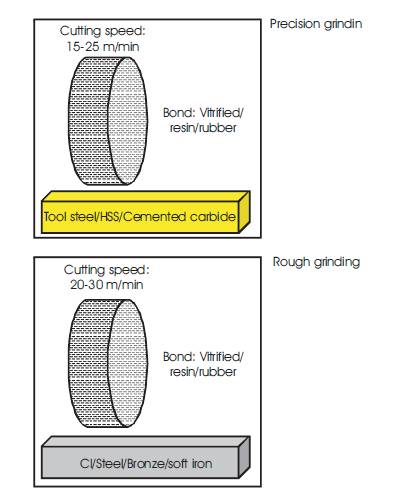
Figure 5. Processing Conditions for Rough Grinding and Finish Grinding
The main issues related to grinding wheels considering the process conditions are the defects formed on them. Major and inevitable defects in grinding are glazing of grinding wheels. After the continuous use, grinding wheel becomes dull or glazed. Glazing of the wheel is a condition in which the face or cutting edge acquires a glass like appearance. That is, the cutting points of the abrasives have become dull and worn down to bond. Glazing makes the grinding face of the wheel smoother and that stops the process of grinding. Sometimes grinding wheel is left 'loaded'. In this situation, its cutting face is found being adhering with chips of the metal. The opening and pores of the wheel face are found filled with workpiece material particles, preventing the grinding action. Loading takes place while grinding workpiece of softer material. The remedies of glazing and loading are dressing of grinding wheels. Dressing removes the loading and breaks away the glazed surface so that sharp abrasive particles can be formed again ready for grinding. Different types of dressing operations are done on a grinding wheel. One of them is the dressing with the help of star dresser. It consists of a number of hardened steel wheels with sharp points on their periphery. The total is held against the face of revolving wheel and moved across the face to dress the whole surface. Another type of wheel dresser consists of a steel tube filled with a bonded abrasive. The end of the tube is held against the wheel and moved across the face. Truing is the process of restoring the shape of grinding wheel when it becomes worn and broken at different points. Truing makes the wheel true and concentric with the bore. Due to continuous use, a grinding wheel may become out of balance. In a balanced wheel, there is a coincidence of centre of mass of the wheel with its axis of rotation. Wheels which are out of balance produce poor quality of surface and put undue strains on the grinding machine. Balancing of wheel is normally done at the time of its mounting on the grinding machine with the help of moving weights around a recessed flange. The Indian Standard Coding system of grinding wheel is IS : 551- 1954. It provides uniform system of coding of grinding wheels to designate their various characteristics. It gives a general indication of the hardness and grit size of any wheel as compared with another. Coding of a grinding wheel consists of six symbols as described. W: Symbol for Manufacturer's Abrasive Type (Prefixed), C: Name of Abrasive, 30 : Grain Size, L: Grade, 5 : Structure Type, R: Bond Type, 17: Manufacturer Symbol for Record (Suffix). The sequence of codes of a grinding should be followed in the same sequence as described above. There are six symbols and first one which is seventh, is optional. It is an optional symbol and the criteria of its assignment entirely depends on the manufacturer's choice. This is a alphabet symbol used to indicate the name of abrasive used. 'A' stands for Aluminum Oxide and 'C' stands for Silicon Carbide. A number provides idea of grain size of abrasives. It is also called grit. This number is decided on the basis of number of holes in one inch length of the sieve used to filter the abrasive particles. Larger number indicates finer grain sizes. On the basis of grain size, abrasive particles can be categorized in four categories as given below. Grain size depends upon the quantity of material to the ground required quality of surface finish; and hardness of workpiece material. Fine and very fine grain size are used for precision grinding, however, coarse and medium grain size is used for rough grinding. Grade of a grinding wheel is the indicative of hardness and tenacity of bond of abrasives. It is represented by capital letters of alphabet 'A'to 'Z' as described below. Selection of grade depends on hardness of workpiece material, grinding speed, contact area of grinding wheel with the workpiece, and capability of grinding machine. Grinding wheels are named as soft, hard or medium hard wheels depending on their grade. Abrasives of hard grinding wheels get blunt quickly, so these are recommended to grind workpiece of low hardness and soft grinding wheels are recommended for hard material workpieces. It includes a number of abrasives and a number of pores in unit volume. The distribution of abrasives and bores decide the structure of a grinding wheel. On the basis of structure, grinding wheels are called dense or open grinding wheel. In case of dense grinding wheels, abrasive particles are densely packed as compared to open grinding wheel with larger porosity. Generally, the structure of grinding wheel is coded in number. Higher number indicates open structure of grinding wheel. Selection of an appropriate structure depends on hardness of workpiece material; required quality of surface finish; and type of grinding operation. Normally, open structure wheels are recommended for rough grinding and for softer materials. Dense structured grinding wheels are recommended for hard and brittle materials. The jig grinding parameters and processing strategies discussed are briefly summarized in Table 4.
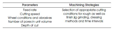
Table 4. A Summary of Jig Grinding Parameters and Processing Strategies
This paper presents a brief review of grinding process with a focus on the emerging technology of jig grinding process, based on the array of research works. This review would be useful in carrying out further investigations on jig grinding process, considering the theoretical as well as practical aspects, and the conclusions of this work can be stated as follows:
Dr. Govindan Puthumana would like to thank the support from H.C. Ørsted Cofund Post-Doctoral DTU project 2014. Sudheesh P K would like to thank the support from Kannur University in 2013 for carrying out the M.Tech project work on Jig grinding process.