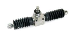
Figure 1. 14" Rack & Pinion Steering
This paper reports on the feasibility of steering system by using, rack and pinion mechanism. In the present era, handling features of an All-Terrain Vehicle (ATV) has become a major aspect. The authors intention is to provide comfort to the driver by reducing steering effort and improve the steerability and handling characteristics of the vehicle. This steering system converts the rotational motion of the ATV into the linear motion to turn the wheels. The steering system design influences the directional response behavior of a vehicle. The steering system plays a vital role in maneuvering the vehicles and they also provide good ergonomics to the driver. Since the steering system is directly controlled by the driver, it is essential to take human comfort into consideration while designing the steering. The vehicle must be able to withstand the rough environment of the off-roads and recreational driving, so it may sustain the traverse over large rocks, downed logs, jumps, mud holes, steep inclines and sharp turns.
Steering system is one of most important part of any vehicle, which is used to provide directional stability to the vehicle. The primary function of a steering system is to steer the wheels in order to take the driver command as an input and provides an overall directional control for the vehicle. A steering system must provide sufficient comfort for the driver to actually sense what is happening with the front tires contact patch as well as enough “feel” to sense the approach to the cornering limit of the front tires. The steering must be fast enough for an e-ATV, so that the vehicle's response to steering and to steering correction to happen instantaneously and it must also have some selfreturning action. The feel, feedback and self-returning action depend on the kingpin inclination, scrub radius, castor angle of the front tire. Positive castor angle improves the self-returning action of the steering wheel, but increases a little steering effort, whereas the negative castor angles reduce the steering effort, of the driver but produce some wheel wandering problems. Higher the Kingpin Inclination (KPI) angle helps in improving self-returning action of the steering wheel and also decreasing the steering effort. Negative camber angle produces higher lateral forces to improve the cornering ability of the vehicle. Moreover, Toe-in angle of the wheels help in improving the straight-line stability, whereas the toe-out angle help in improving the cornering stability. Negative scrub radius helps to stabilize the effect of vehicle handling. Hence, proper alignment of the wheels helps in achieving better steerability and handling characteristics of the vehicle.
John C. Dixon (2009) revealed that directional control of a road vehicle is normally achieved by steering the front wheels, that is, by rotating them about a roughly vertical axis. The steering system must connect the hand steering wheel to the road wheels with the appropriate ratio, and also meet other geometric constraints, such as limits on bump steer [1].
William F. Milliken, and Douglas L. Milliken, (1995) revealed that wheel geometry contributes a lot to the steerability of a vehicle and a slightest misalignment creates problems like steering pull and vehicle drift [2].
Wong, J. Y. (Jo Yung) (1976) revealed that the design of the steering system should be such that to minimize tire scrub during cornering of vehicle and the wheels should follow curved paths with different radii [3].
Jack Erajevec (2005) revealed that in rack and pinion steering linkage, steering input received from a pinion gear attached to the steering column directly and it creates some problems while maneuvering [4].
Reza N. Jazar, (2008) revealed that the inner wheel of a vehicle in a high speed turn must operate at a lower steer angle than kinematic steering. Reducing the steer angle of the inner wheel reduces the difference between steer angles of the inner and outer wheels [5].
Richard Stone & Jeffrey. K. Ball (2004) revealed that the layout is governed by the ratio of track (distance between the wheels) to wheelbase (distance between front and rear wheels) [6].
The primary focus of the work is to provide the suitable steering system to the driver to manipulate the association of the vehicle by turning the wheels. In this paper the authors have carried out a study and design of the steering system for an electric ATV. It must be structurally stiff to avoid deflections through its components.
Based on the literature survey, various problems are identified like steerability, steering drift, etc., due to improper steering alignment. The work done in this paper concerns the effect of various steering parameters and the development of a CAD model and carrying out related simulations to study the effects of different wheel geometry parameters on steering.
Rack and Pinion steering is used in most of ATV's because of the following reasons:
Helical Gears are used in Rack and Pinion steering in order to allow a large transverse contact ratio [7].
The authors selected a 14” Rack and pinion unit (Figure 1), which is suitable for an ATV. Rack and Pinion Specifications are shown in Table 1.
Figure 1. 14" Rack & Pinion Steering
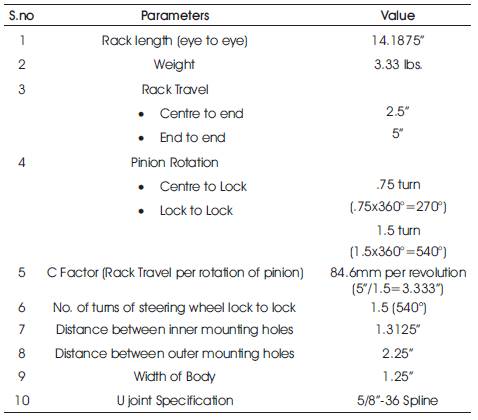
Table 1. Steering Parameters
Radius of pinion can be found out by equating rack travel in one rotation of pinion and circumference of pinion.
2 π Rpinion = rack travel in one rotation of pinion
2 π RPinion = C Factor
2 x π x RPinion = 84.6 mm
RPinion = 13.47 mm
Radius of pinion will be 13.47 mm.
Three types of steering geometry commonly seen are,
The angle turned by inner wheel is more than the angle turned by outer wheels. Ackerman condition is required when speed of the vehicle is too small and slip angles are zero.
It is also called Reverse Ackerman geometry. The angle turned by inner wheel is less than the angle turned by outer wheel. It helps to compensate large differences in slip angles between inner and outer front tire while cornering at high speed.
The angle turned by inner wheel is same as the angle turned by outer wheel.
Low speed or kinematic steering is defined as the motion of a wheeled vehicle as determined by pure rolling of the wheels. The velocities of the centers of all the wheels lie in their mid-plane, i.e., the side slip angles α are vanishingly small. In these conditions, the wheels can exert no cornering force to balance the centrifugal force due to the curvature of the trajectory.
The views of Steering Geometry in Top View, Front View and Side View are shown in Figures 2-4 respectively.
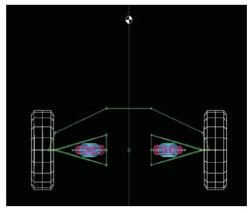
Figure 2. Steering Geometry in Top View
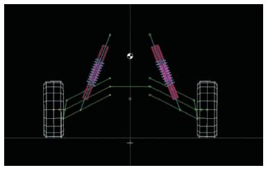
Figure 3. Steering Geometry in Front View
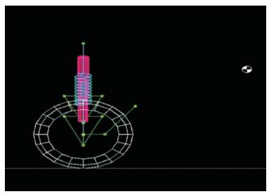
Figure 4. Steering Geometry in Side View
For low speed & no slip (correct steering),
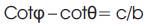
Kingpin Center to center distance, c=50.57”
Wheelbase, b=57.56”
Tie rod length = (492.87 x2) =985.74 mm
(To minimize Bump Steer)
Inner wheel locking angle, θ=40⁰
(As Per Simulation on Lotus Software)
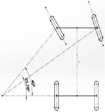
Figure 5. Inner Angle and Outer Angle
The Calculation of Outer Wheel Locking Angle (φ) is derived from Figure 5.
By Ackerman equation,
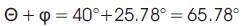
Total angle turned by wheel lock to lock,
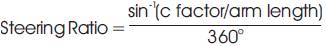
The steering ratio is defined as the number of degrees of steering wheel that must be turned to pivot the front wheel by one degree.
In other words, it is the ratio of angle turned by wheel in 360° rotation of the steering wheel.
Higher will be steering ratio (As in passenger cars 14:1 to 20:1), less effort required to turn the steering wheel, but the number of turns would also increase for obtaining same deviation of the wheel.
Lower will be steering ratio (As in Equation (1), ATVs, etc.), more efforts are required to turn the steering wheel, but the number of turns would also decrease.
Since, Maximum angle turned by wheel lock to lock=65.78°,
Maximum angle turned by steering wheel lock to lock=540°;
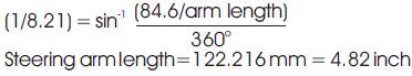
Steering Ratio= 540/65.78 = 8.21;
Steering Ratio= 8.21:1.
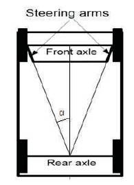
Figure 6. Steering Arms
From Figure 6,
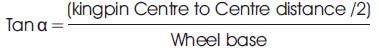
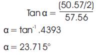
Since,
Average Steer angle(δ),
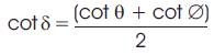
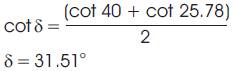
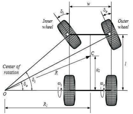
Figure 7. Turning Circle Radius
Turning circle radius (Figure 7) can be calculated by [8],
Since, a2 =17.57”
R= [17.572 + (57.56 cot 31.51)2]5
R = 95.52” = 2.426 m
Turning Circle Radius= 2.426 m.
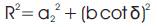
In the design of the steering geometry, the bump steer and roll steer effect should be considered. Bump steer results from the combination of wheel toe with wheel and the vertical travel of wheel, while the roll steer is produced by the combination of toe in or toe out and body roll. The suspension and steering links should be placed in such way to minimize the distortion of the steering geometry with suspension movement [9]. For this reason, to minimize the bump steer (Figure 8), the steering tie rod should be parallel with the upper wishbone and to minimize roll steer, the upper wishbone inboard pivot points should be in the same vertical plane with tie rod inboard pivot point. Therefore, Tie Rod Length is calculated by the CAD Software.
Tie Rod Length= 492.87 mm = 19.404”
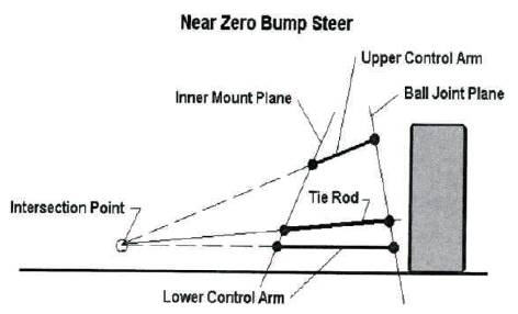
Figure 8. Minimization of Bump Steer
The determination of Steering Parameters are from Figure 9.
Figure 9. Steering Parameters
IBJ Centre Distance = 180.18 mm
OBJ Centre Distance = 590.807 mm
Distance of Rack from front axle = 11”= 279.4 mm
For high speed turning, turning radius of vehicle is much larger than wheelbase [10] (Figure 10).
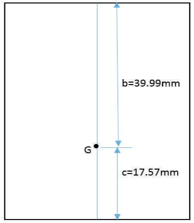
Figure 10. Position of C.G
Sum of forces in Lateral direction equals to mass times centripetal acceleration.
Calculation on high speed turning,
Fyr = Rear axle lateral force
Fyt = Front axle lateral force
Fy = CG lateral force= Centrifugal force =mv2/R
where, m= 380 kg,
V=25 km/h = 6.944 m/s,
R=4 m.
Fy = mv2/R
Fy = (380 x 6.9442)/4= 4581.4 N
Also,

Where,
Put Equation (7) in Equation (6)
Fy =Fyr(1+c/b)
∴mv2/R= Fyr(1+c/b)
∴Fyr = (mv2/R) X [b/(b+c)]
∴Fyr = (4581.4) X (39.99/57.56)
Fyr = 3182.94 N=715.55 lbs
Fyf = Fyr× c/b
Fyf =1398.46 N=314.386 lbs
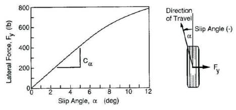
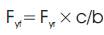
Figure 11. Determination of Slip Angle
By the graph interpolation (Figure 11), the authors find,
Front wheel slip angle αf =3.6o
Rear wheel slip angle αr =9.7o
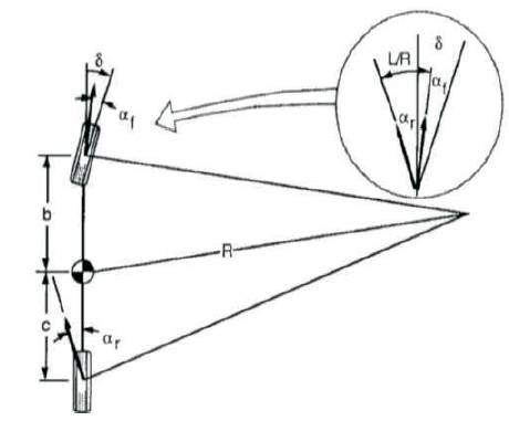
Figure 12. Cornering of Bicycle Model
Cornering stiffness of Front wheel (Figure 12),
Cαf = Fyf/αf = 1398.46/3.6
Cαf =388.46 N/degree
Cornering stiffness of Rear wheel (Figure 12),
Cαr = Fyr/αr = 3182.94/9.7
Cαr =328.14 N/degree
∴Fyf = [(mxc/(b+c)] x (v2/R)
= mass x acceleration
∴Wf/g=mc/(b+c)
∴Wf = [mc/(b+c)] x g
∴Wf = 1137.89 N
Similarly,
∴Fyr = [(m x b/(b+c)] x (v2/R)
= mass x acceleration
∴Wr/g=mb/(b+c)
∴Wr =[mb/(b+c)] x g
∴Wr = 2589.9 N
For the given parameters,
Calculation of steering condition,
Wf/Cαf = 1137.89/388.46
Wf/Cαf = 2.929
Wr/Cαr = 2589.9/328.14
Wr/Cαr = 7.893
Wf/Cαf < Wr/Cαr → K<0 → αf < αr
This condition satisfies oversteer. So this vehicle is oversteer.
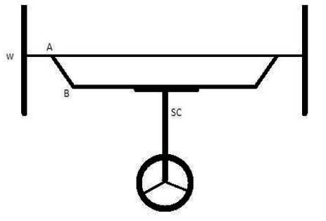
Figure 13. Steering Geometry
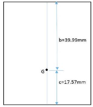
Figure 14. C.G. Position
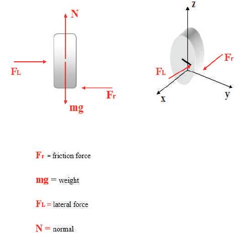
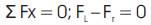
Figure 15. Forces Acting on Wheel
The Steering Effort is determined from Figures 13-15.
Mass with driver, M=450 kg
Taking moment about rear axle,
Mf x (b+c) = M x c
Mf x 57.56 = 450 x 17.57
Mf = 137.36 kg
This force will be acting on two wheels, so for one wheel, Mf =137.36/2=68.68 kg.
The load acting on the Single front wheel,
N=68.68 X 9.81=673.75 N
This force appears when the car is stopped and it starts the movement of the wheel.
From equation (8) they calculate
FL = Fr
From equation (9),
N = mg
Now, wheel resistance due to cornering of wheel is foundout,
FS =0.7 × 673.75
FS = 471.625N
It is the force that the rack has to transmit to the tie rods and these to the steering arms to move the wheel. Now, they can calculate the torque on the pinion.
To calculate the torque use the following equation:

Radius of pinion=13.47 mm.
=471.625 X 13.47
=6352.78 N-mm= 6.352 N-m
Torque on steering wheel=6.352 N-m
This is the torque in pinion and it is transmitted through the steering column.
Finally, they calculate the necessary tangential force that must be made in the steering wheel by the driver to turn the wheels.
T = F X Rsteeringwheel
Steering Effort or Force applied on steering wheel=Torque on steering column.
Radius of steering wheel,
= 6352.78/150
= 42.352 N
It is the force when the car is stopped, the moment when it is forced to turn the wheels has the highest value.
There have been so many efforts made to minimize the steering error. As a matter of fact, we should remember the following points:
All these facts may reduce the importance of the steering error and also suggest that this issue should be considered. Steering error has a significant effect on tire wear of the front wheels and on steering wheel self-alignment, influencing the driver's feel of the steering wheel [11].
The conclusion of this paper is that to select an appropriate Rack and Pinion steering system for the electric ATV and also helps to enhance the stability of vehicle because of avoiding the bump steer by placing the suspension and steering links in such a way to minimize the distortion of the steering geometry with suspension movement. It is cheaper and easily ser viceable and can be manufactured at mass level. The idea behind steering is that, a vehicle requires less driver input for any steering maneuver if front wheels are steered in the vehicle.
As the design component of the paper, various mathematical formula was derived from the fundamental to calculate the turn radius, behavior of steering, exact steer angle under the Ackermann principle, which calculates various steering values needed such as Ackermann angle, length of tie rod, steering ratio, steer angle etc. under assumptions of some basic values of the vehicle.
Steering is a main component of any vehicle which must be properly designed, that works well and guides the vehicle to move in correct direction. This paper gives almost all information about the steering system available today for an electrical ATV. The design and simulation part of the paper is recommended as a ergonomically viable technique given its superiority in terms of maneuverability compared to the conventional steering design approach. Various mathematical formula was derived from the fundamental to calculate the steering effort, turning radius, nature of steering, etc.
In addition, this paper recommends further work to:
The authors working on “Design of Steering System for an Electric All-Terrain Vehicle”, would like to thank all those who have sincerely and whole heartedly lend their support and contributed to this project. They express the gratitude and thankfulness to the professors for their valuable guidance and their co-operation in this project.
They are also very much thankful to the project guide Dr. V.K. Saini (Head of Department, Mechanical Engineering) for her inspiring guidance with helpful suggestions for the project. They are greatly obliged to the entire staff of the Department of Mechanical Engineering and would like to extend their appreciation and gratitude to Mr. Sumit Kumar Singh (Captain - Team Zero Gravity), who helped to gain valuable insight into the topic.