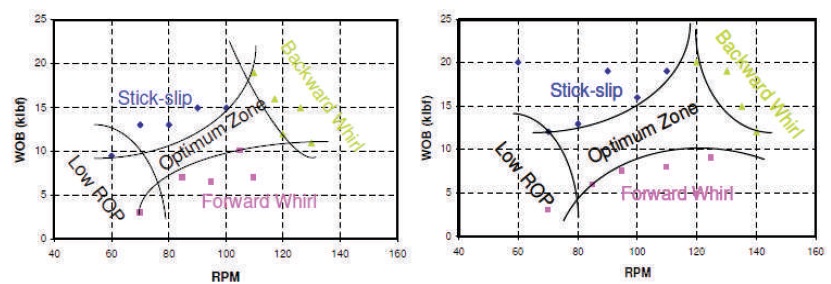
Figure 1. Typical Drilling Optimization Maps to Identify the Optimum Operation Zones (Dong & Chen, 2016)
This paper provides an analysis of one of the dysfunctions in borehole drill strings, which is torsional vibration. Additionally, an analysis of mitigation through systematic adjustment of the key parameters of Weight on the Bit (WOB) and Rotations per Minute (RPM) is conducted. One of the key forms of dysfunction is undesired vibration and shocks on the drill strings. The vibration and shock experienced by drill strings have a detrimental impact on equipment life, resulting from damage to the drill bit and the drill string components. This paper studies a generalized lumped-parameter model of the drillstring system to provide a fundamental understanding of the torsional stick-slip vibrations during drilling operations. The impact of various parameters such as the weight on the bit, rotational speed, and damping on the severity of vibration, in particular, stick-lip vibration, is analyzed. Various passive, active, and semi-active control strategies to mitigate the torsional vibrations have been studied and implemented with varying degrees of success, subject to continual development. From the simulation, the WOB, the drive torque, and rotational velocity determine the stick-slip onset and severity. This paper focuses on active control of the rotational speed and the weight on the bit by systematic adjustment to eliminate stick-slip while avoiding other undesirable effects and thus achieving optimum performance. Further study will be on multi-stability analysis to define the optimum operation zones and the design of vibration reduction tools and control strategies.
Borehole drilling is a growing activity driven by the need to access important resources such as groundwater, fossil fuels, and mineral exploration. The borehole drilling process entails making a deep hole in the ground down to several meters using percussion or rotary drill tools. The drilling tools generally consist of the string comprising the bit that cuts the rock and the pipe system that transmits the drilling torque from the rotary system. Drilling fluid is pumped through the pipe and the bit center to clear debris from the cutting process and transport it all the way up to the surface around the annulus of the drill pipe and the borehole. This process also provides lubrication, damping, and cooling to the string. The drive mechanisms at the top of the shaft cause the shaft to rotate at the required speed, while the hoisting system allows for up and downward movement of the strings to allow additional pipe length as drilling goes deeper, control of the applied force to the drill bit, and final removal of the drill strings. The process is fraught with various challenges, which can result in undesired vibration and shocks on the drill strings. Vibration and shock have a detrimental impact on equipment life, resulting in damage to the drill bit and the drill string. Premature bit and drill string component failures are, to a large extent, associated with mechanical vibrations in the bottomhole assembly (Navarro-López & Suárez, 2004). Statistics indicate that 25% of non-productive time in drilling operations arises from vibration and shocks (Tian et al., 2019). Excessive stick-slip vibrations of the drill string system are usually the primary cause of premature failure of the drill string and low drilling efficiency, as per studies by Dong and Chen (2016).
It is thus imperative that these vibrations and shocks are controlled in order to optimize the operational and cost performance of drilling operations. Dysfunctions in the form of Vibration and Shocks (V&S) can be torsional, axial, or lateral. These can be mitigated by geometric design, passive and active control of key parameters. Studies of vibrations and shocks in drill strings have been ongoing since the early 1960s, focusing on the BHA dynamic behavior with focus moving to the entire drill string and the rock bit interactions (Tian et al., 2019). Research output from these studies has resulted in the development of a generally accepted concept of the problem characterization and mitigation strategies. In this paper, mitigating torsional vibration is the focus. Torsional vibration arises from the nonlinear frictional interaction between the bit and the rock and at worst results in complete stalling of the bit or intermittent stalling of the bit resulting in a phenomenon of stick-slip oscillation. When stick-slip sets in, the bit stalls then slips as torsional energy is built up in the drill pipe elasticity, and due to the antidamping characteristics of the bit rock friction characteristics, the bit accelerates to high rotational speed higher than nominal in a cyclic manner.
In order to characterize the dynamics of the drill string, it is modeled as a suspended torsional pendulum suspended by a slender string (L >> d). Lumped parameter models separating the rotary drive, the drill pipes, the drill collars, and the drill bit have been developed, and various combinations in varying degrees of freedom have been developed. Navarro-López and Suárez (2004) used the two Degrees Of Freedom (DOF) model, lumping the BHA and the pipes as one element and the rotary as a separate element.
In all models, the string is then modeled with single and multi-degree of freedoms and varying boundary conditions. (Zhu et al., 2014) summarize research on stickslip vibration, including mechanical models and experimental field investigations, comprising lumped parameter single degree and multi-degree of freedom. From previous research, it is generally agreed that the interaction of the drill bit and the rock is the key source of vibration excitation, which creates torsional, lateral, and axial vibration due to complex nonlinearity. Various authors have modeled the bit-rock interaction as dry friction, with non-linearity around zero velocity and decaying law with an increase in velocity, giving it antidamping characteristic. The Karnopp (Karnopp, 1985) model, which switches to 3 modes, is the most widely used, and others have introduced continuous functions in varying forms, all showing speed-dependent decay characteristics.
The modeling in vertical strings is now largely in conformity with field and experimental results. The effect of many other parameters, e.g. lithology, bit-rock interaction area, is still under extensive study. The insights from the dynamic modeling of the drill strings help characterize the source and nature of the vibrations and shock. This then leads to the formulation of strategies and devices to mitigate the detrimental effects of vibration and shocks. Various research outputs have shown that the bit rotational velocity, weight on the bit, and viscous damping have significant effects on the nature of the vibration, and their control and manipulation can reduce stick-slip vibration (Tian et al., 2019; Navarro-López & Suárez, 2004), as shown in Figure 1.
Figure 1. Typical Drilling Optimization Maps to Identify the Optimum Operation Zones (Dong & Chen, 2016)
Various strategies based on passive and active control have been developed and implemented with varying degrees of success, and this area is the subject of extensive research by industry and academia (Dong & Chen, 2016).
The industry has developed various passive devices and active control strategies to reduce vibration. In addition, downhole parameter measurement schemes are continuously being developed. Navarro-López (2009) presented some experience-based control strategies for mitigating stick slip using velocity control at the top drives and manipulation of the BHA. Other solutions include variation of WOB, RPM, introduction of a shock absorber subs, reamers along the drill string, depth of cut control on the drill bits, etc.
Given the potential losses or costs that arise from drill string dysfunction, a lot of effort has been put into mitigation through initial engineering designs and operational control measures. Controls are divided into passive and active control systems, and some semi-active systems, of which passive control does not need external energy sources but uses the energy of the system.
Resonance has been identified as one of the key risks, and as such, its prevention in design and operation is a fundamental mitigation or passive control method. This is achieved through geometric optimization of the drill string for the full operating range. Methods used to solve the natural frequency of drill strings vary from trial and error to analytical methods. Those that work for vertical strings do not necessarily work for horizontal strings, and the effect of the BHA length on the natural frequency is significant.
Optimizing drilling parameters dynamically is also a way of preventing resonance. This has led to the establishment of general optimization maps, as shown, whereby stability in the optimum zone can be guaranteed. The zones referred to as "sweet spots" in some literature depend by and large on the rock lithology. The optimum zone with respect to vibration only can be such that drilling efficiency is reduced, thus the need for multi-objective optimization. Another way to optimize the BHA is by adjusting the quantity and position of stabilizers or reamers. However, while adjusting the resonant frequency can cause backward whirl and stick slip vibration through torque mutation.
Active controls aim to apply opposing forces to external vibration and are divided into three main classes: wellhead control, bottom-hole control, and complete string control. The control law is derived from considering the drill string dynamic model and external parameters such as RPM, WOB, and damping. Indirect controls are achieved by adjusting RPM and WOB, with PI controllers based on a spatial distribution model. Variations to these controllers have been in the form of improved state feedback, state controllers with WOB feed-forward, and single-inputoutput control of the WOB, as in the D-O skill (Canudas-de- Wit et al., 2008) control the WOB. Other improvements have been in the form of error compensation to control uncertain factors and instability of the system caused by friction. Stick slip control mode is based on GA with leadlag compensator and PID integrated controller. A method of controlling stick slip by decomposing the traveling wave of torsional vibration was done by (Tucker & Wang, 1999) and (Kreuzer & Steidl, 2012) with sensors placed a short distance above the surface, obviating the need for down hole measurements. A system using torque feed known as soft torque effectively removes the inertia of the top-drive to limit the buildup of torsional energy to stick-slip level using torque measurement at the well head.
Schlumberger has commercialized and converted this system into practice (Canudas-de-Wit et al., 2008). However, active control is still an area of extensive study as controllers developed so far still have limitations in performance in various drilling scenarios. Proportional Integral Derivative (PID) based on a stable stick-slip model with full system feedback and estimation was unstable in some practical situations. Well-head control is easier, but observation of the real down-hole condition is difficult.
In general, controllers are based on classical control theory and provide good simulation results. However, challenges with accurate down hole measurement, the complexity of calculations, and the difficulty in developing hardware have limited their application to operator-advisory systems. Full automation remains an area of extensive research. An adaptive method to take control of limited feedback is to sense the BHA conditions and intermittently transmit them to the operator or controller for adjustments. Limitations of conventional passive and active controllers have led to a focus on the development of semi-active control devices that use magnetic fluid with controllable viscosity.
In this paper, the reduced-order Proportional Integral (PI) controller is optimized for step response and is used to control the RPM and the WOB to guide the operator to operate in the optimum zones. A semi-automated program is developed and analyzed to get the operations out of an oscillatory mode.
In order to mitigate drill string shock and vibration, ongoing research is being conducted on drill string dynamics, both theoretically and experimentally. According to several authors and researchers, it is generally accepted that the source of stick-slip is the nonlinear frictional interaction between the bit and the rock. The drill string is generally modeled as a suspended torsional and axial pendulum with distinct components, including the drive system or rotary, the drill pipe system extending from the pipe at the top to "n" pipes depending on the depth, the drill collar, and the drill bit. The pipe is connected to the drive, which is generally considered a flywheel with high relative inertia. The pipe is elastic with damping, as is the collar, drill bit, and any other mitigation devices. At the ends, the motor torque Tm, or U, drives the pipe, and the bit is subjected to torque arising from the cutting face, the dynamic frictional force of the bit-rock interaction, and the damping force from the drill fluid system. The physical arrangements of a typical drill string and associated torsional, lateral, and axial models are shown in Figure 2.
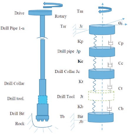
Figure 2. The Torsional Modelling of the Drill String
Additional damping/tool devices can be added on top of the collar or between the collar and the bit. The generalized equation of motion from the lumped parameter models is given by Equation 1,
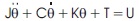
where, J being the diagonal matrix of inertias of each component, K is the stiffness matrix, and C is the damping matrix, θT is the matrix of displacements of each component.
T is the torque matrix = [Tm 0 .. Tt Tb] and the U is T Control matrix = [U 0 .. 0 0]T.
The bit torque interaction model is based on the Karnopp and Stribec models is and characterized by a decaying friction law whereby at low speeds the friction coefficient is high at μsb (static) and decays with increased velocity exponentially to μcb (Coulomb), giving it an anti-damping characteristics per the formulae used.
Dry friction shows non-linear characteristics near zero, leading to the adoption of a switching model (Karnopp, 1985), with the decay function inspired by experimental results as shown in Figure 3. The dry friction models have been studied by various researchers (Leine et al., 1998; Pavone & Desplans, 1994). The bit torque arising from the frictional interaction Tfb thus assumes three distinction values namely the static torque Tsb, dynamic torque Td depending on the velocity and difference between the coefficients, and the reaction torque, and given as Equation 2.
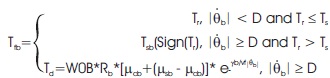
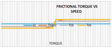
Figure 3. Dry Friction Characteristics
where D is the threshold speed considered as detection of stalling is essential for computational efficiency as zero cannot be modelled.
Tr is the reaction torque = C ( ) - )) + K ( - )) - Tab ( )
μcb is the dynamic friction coefficient
Yb is the relation between the dynamic and static coefficients and
Vt is the velocity factor to make it dimensionless.
The frictional force in dry friction is proportional to the normal force acting between the surfaces and is independent of the contact area. The relationship between the frictional torque and speed in dry friction can be represented by a graph, which is commonly known as a frictional torque vs. speed curve.
The dry friction characteristics graph is shown in Figure 3.
Canudas-de-Wit et al. (2008) propose to use the Weight on the Bit (WoB) force as an additional control variable to extinguish limit cycles when they occur. An approximate analysis based on the bias describing function and completed with some simulations provides good evidence that the rotational dynamics of the oil well drill string displays such a behavior. In particular, we propose an adaptation law for the WoB named D-OSKIL mechanisms, which results from a variant of the Oscillation Killer (OSKIL) mechanism.
Dong and Chen (2016) depicts the control technologies for drill string V&S as being divided into passive control, active control, and semi-active control. Key methods and critical equipment for three types of control systems are compared. Based on the past development, a controlling programme for drill string V&S is devised. Application technologies of the drill string V&S are discussed, such as improving the rate of penetration, controlling borehole trajectory, finding the source of seismic while drilling, and reducing the friction of the drill string.
Karnopp (1985) says stick-slip friction is present to some degree in almost all actuators and mechanisms and is often responsible for performance limitations. Simulation of stick-slip friction is difficult because of strongly nonlinear behavior in the vicinity of zero velocity. A straightforward method for representing and simulating friction effects is presented. True zero velocity sticking is represented without equation reformulation or the introduction of numerical stiffness problems.
Kreuzer and Steidl (2012) present a method for controlling these vibrations by exactly decomposing the drill string dynamics into two traveling waves traveling in the direction of the top drive and in the direction of the drill bit. The decomposition is derived from the wave equation governing the string vibrations and is achieved with only two sensors that can be placed directly at the top drive and at a short distance below the top drive. Therefore, down-hole measurements along the string and at the bit are not necessary, which is a major advantage compared to other control concepts for drill string dynamics.
Simulation and experimental field results have shown that the drill string exhibits multi-stability characteristics with three key stable states, i.e., constant stable rotation, oscillatory behavior, characterized by stick-slip phenomena due to non-linearity as shown in Figures 4 to 6.
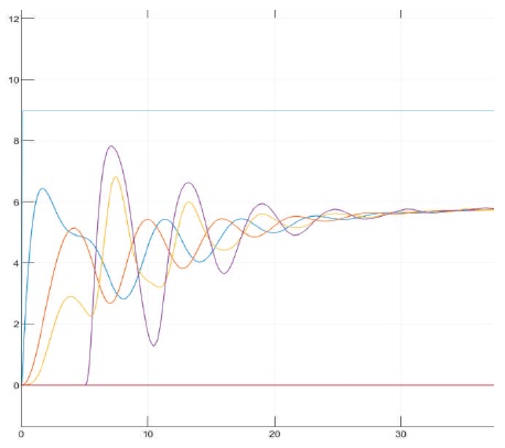
Figure 4. Slip-Phase
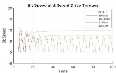
Figure 5. Effect of Drive Torque and Rotational Speed
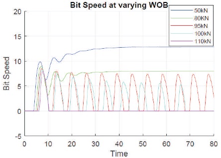
Figure 6. Effect of Weight on the Bit (WOB)
In the slip phase, all components experience acceleration to steady-state speed at various torques above the threshold. Below the threshold, the bit intermittently sticks and slips. In analyzing the stick-slip oscillations, the influence of some factors was analyzed, and the general characteristics were observed. Under certain conditions, all components experience acceleration to steady state speed at various torques above the threshold.
Higher drive torque results in higher rotary speed and eliminates the tendency to stick slip. The rotary speed to determine the critical speed at which stick-spick is eliminated. The graph for the effect of drive torque and rotational speed is shown in Figure 5.
The lower the WOB, the less the tendency to experience stick slip. In the slip phase, all components experience acceleration to steady state speed at various WOB below the threshold, as shown in Figure 6.
The viscous damping coefficients at the BHA are low; at lower viscous damping, the stick-slip phenomenon manifests, and as the damping coefficient increases, the stick-slip phenomenon diminishes and can be eliminated at higher damping,
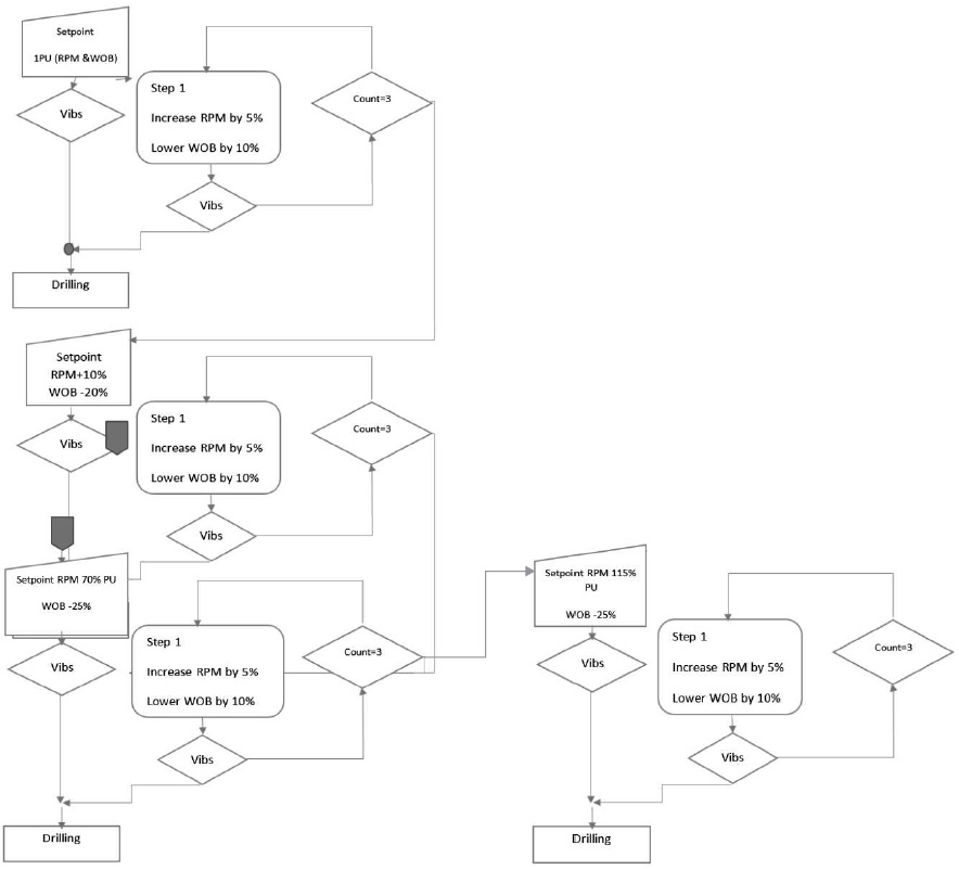
The simulation highlights the significance of key factors such as the Weight on the Bit (WOB), drive torque, and velocity, which can be manipulated to eliminate stick-slip. Figure 7 illustrates this process. However, care should be taken to avoid other undesirable effects, such as excessive reduction in WOB, which can rapidly decrease the rate of penetration, or higher speed, which can generate increased lateral vibration. Therefore, the optimum zone for each combination of WOB, RPM, and rock formation should be defined to achieve optimum performance.
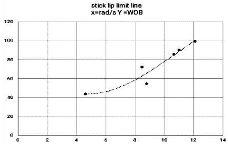
Figure 7. Vibration Optimization Map WOB-RPM
A proposed program has been developed and analyzed to eliminate stick-slip oscillation by progressively varying the rotational speed in Rotation Per Minute (RPM) and Weight on the Bit (WOB). The program aims to minimize the duration of operation under torsional vibration. In this paper, the PI controller with optimized parameters is used as the speed controller. The vibration can be cured by adjusting WOB and RPM. Vibration optimization map WOB-RPM is shown in Figure 7.
This analysis investigates the influence of various model parameters on the stick-slip phenomenon in both stick and slip situations. The drill string model, combined with frictional bit-rock interaction models, is simulated using Simulink. This can help formulate strategies and techniques to mitigate stick-slip problems while optimizing drilling operations. A program for systematic variation of WOB and RPM was developed in Simulink and run with various initial conditions. The results are shown in Figures 8 to 13.
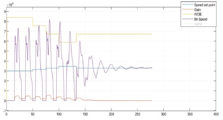
Figure 8. Drill Performance Starting at 3 RPM and WOB=85 kN
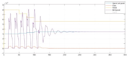
Figure 9. Drill Performance Starting at 3RPM and WOB = 80kN
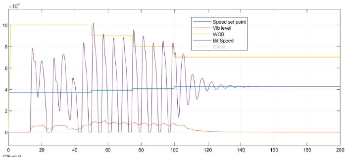
Figure 10. Drill Performance Starting at 3.8 RPM and WOB=100kN
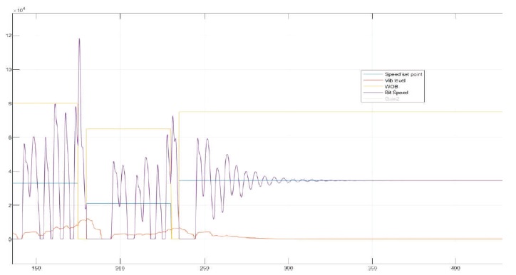
Figure 11. Drill Performance Starting at 3.5 RPM and WOB=80 kN (Vibration Only Curing In Third Stage)
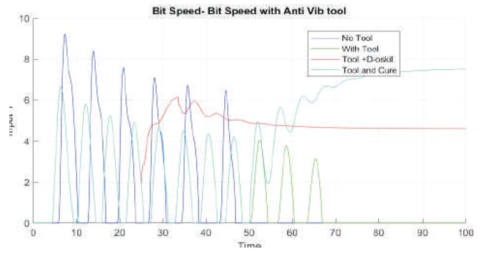
Figure 12. Drill Performance Starting at 3RPM and WOB=105kN With Anti Stall Tool and Cure program
Starting a drill at a low RPM with a high WOB can cause the drill string to experience high levels of torque and torsional vibration, leading to issues such as drill bit bounce and stick-slip. This can reduce the Rate of Penetration (ROP) and increase tool wear. Starting at a low RPM can also result in reduced ROP, particularly in harder formations where a higher RPM may be required to break up the rock effectively. A high WOB can generate more heat, causing thermal damage to the drill bit and reducing its lifespan. Figure 8 shows the graph for drill performance starting at 3 RPM and WOB = 85kN.
Starting at 3 RPM may result in a lower ROP than a higher RPM, but it can help reduce torsional vibration and shock in the drill string, increasing tool life and reducing the risk of tool failure. A WOB of 80kN is relatively high, increasing the stress applied to the drill bit and other drill string components. However, a WOB of 80kN may still be within an acceptable range for drilling conditions and improve ROP by applying more force to the bit. Figure 9 shows the drill performance starting at 3RPM and WOB = 80kN.
In general, higher RPM and WOB can increase the drilling rate and efficiency, but can also increase the risk of drill string torsional vibration and shock, leading to equipment failure, reduced drilling performance, and increased operational costs. The bit speed and set point are more frequent compared to 3 RPM and WOB = 80kN. The drill performance starting at 3.8 RPM and WOB = 100kN is shown in Figure 10.
Figure 11 shows a plotted graph of the drill performance starting at 3.5 RPM and WOB=80 kN, with the speed set point initially maximized and then kept low as the value increases.
Figure 12 shows the plotted graph for drill performance starting at 3 RPM and WOB=105 kN with an anti-stall tool and cure program. Here, the anti-stall tool and cure program start with high values and diminish as time progresses.
The influence of various factors on stick slip was analyzed using various parameters. The drive torque provides thresholds for which stick slip occurs under different conditions. Higher drive torque results in higher rotary speed and eliminates the tendency to experience stick slip. The viscous damping coefficient at the BHA is also a key factor, with lower values resulting in the manifestation of stick slip and higher values leading to its elimination. The effect of Weight on the Bit (WOB) is another controllable variable that can be used to avoid stick slip. Lower WOB values reduce the tendency to experience stick slip. During the slip phase, systematic control of the combination of WOB and rotational speed can cure vibration. This can be supplemented with other mitigation measures such as the anti-stall tool, especially in situations where the pressure in the chamber is higher than the pressure in the annulus (the space between the drill string and the wellbore wall), which creates a pressure differential across the bit. This pressure differential helps prevent the formation from sticking to the bit and reduces the risk of stalling.
The stick-slip phenomenon was effectively modeled, and the model and simulation outputs agree with field and experimental observations. The simulation highlights the significance of key factors such as WOB, drive torque, and velocity, which are controllable variables that can be used to eliminate stick-slip. However, it's important to be cautious when manipulating these factors to avoid other undesirable effects such as excessive reduction in WOB, which can rapidly reduce the rate of penetration, and higher speeds, which can generate increased lateral vibration. Additionally, excessive WOB can cause issues such as drill string buckling or borehole instability, so it's important to optimize the WOB based on the specific drilling conditions.
High drive torque can cause the drill string to twist and oscillate axially, leading to stick-slip, while high velocity can cause the drill string to whip, leading to the same issue. To reduce the likelihood of axial oscillations and eliminate stick-slip, the drill bit speed should be slowed down. Therefore, defining the optimum zone for each combination of WOB, RPM, and rock formation is crucial to achieve optimum performance. Systematic manipulation of the WOB and RPM using optimized PI controllers can mitigate stick-slip and guide the operator to operate in the optimum zone. Further research into the various mitigations of stick-slip and other forms of vibration and shock is being pursued.
The author declares that there is no conflict of interest regarding the publication of this paper.