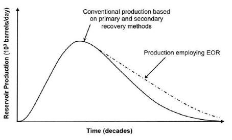
Figure 1. Use of EOR to Improve Production
The demand for petroleum is increasing steadily, with the International Energy Agency (IEA) projecting that the world's petroleum expenditure will rise from 3564 Million Tonnes of Oil Equivalent (MTOE) in 2007 to as much as 5471 MTOE in 2015 and 6301 MTOE in 2030. More than two-thirds of the oil discovered around the world remains unrecovered; 40–70% of the original oil is still left in place after using conventional production techniques, namely, primary and secondary recovery techniques. This paper is based on the use of the Thermal Enhanced Oil Recovery (TEOR) method in a Sudanese oil field, the Orion field. There are two types of thermal EOR methods, namely In-Situ Combustion (ISC) and Hot Fluid Injection Process. The selection of a specific thermal EOR method is crucial for economic production. Also the challenges faced, such as depth limitation, conventional completion problems, reservoir heterogeneity, etc. are discussed. In order to get maximum recovery from the field, it is necessary to select a shallow depth so that heat loss does not occur inside the formation.
A procedure for recovering oil that has not already been recovered using primary or secondary oil recovery methods is known as enhanced oil recovery, sometimes known as tertiary recovery. Due to their complexity and high cost, enhanced oil recovery techniques are only used after primary and secondary recovery methods have run their course (Tewari et al., 2011). It may not even be cost-effective to use EOR, depending on circumstances like the price of oil. In some scenarios, the remaining oil and gas may be left in the reservoir since it is just not financially viable to remove them. Scientists and petroleum firms are interested in EOR because it has the potential to increase the lifespan of wells in known or future oil resources. However, EOR procedures frequently have negative environmental consequences, such as causing harmful chemicals to leak into groundwater. As shown in Figure 1, EOR effectiveness over time is compared to primary and secondary production. The production curve in this graph represents the general trend of production. A realistic production curve may have many peaks and faults during the exponential production phase.
Figure 1. Use of EOR to Improve Production
Tewari et al. (2011) objective was to implement and evaluate the cyclic steam stimulation method in the heavy oil fields of Sudan. The Fula oil field is in the Muglad basin. The field has been divided into four fields, namely Fula Main, Fula Central, Fula North and Fula North East. The stratigraphic framework of the Muglad Basin comprises, in ascending stratigraphic order, the Albian-Cenomanian Bentiu formation overlying the lower Toarican Aradeiba formation. The Bentiu formation has higher porosity and permeability with 29-34% porosity, followed by the Aradeiba formation with 27-28% porosity and heterogeneity throughout, and the Abu-Gabra formation has lighter crude oil with lower porosity and permeability than the bentiu formation. The formation of bentiu is aided by strong acquisition support. The bentiu formation is shallow, with a formation depth of 550–600 m. Heavy oil is discovered in the shallow region, while light oil is discovered in the depths, specifically in the Abu-Gabra formation. The bentiu formation has an excellent net pay of 28.7 million. Fula North East (FNE) field is a mediumsized oil field at a shallow depth of 550–600 m. Oil is found in all three formations, out of which the bentiu formation holds >90% of Stock Tank Oil Initially In Place (STOIIP). A field development plan has been considered for this formation.
First, it was decided to develop primary fields as Cold Heavy Oil Production With Sand (CHOPS).It was recognized early on that heat would be required to reduce the viscosity of the heavy crude oil in the FNE field in order to increase well productivity and improve overall recovery factor. The expected primary recovery in the Fula North East field is lower, around 19%; the reservoir depth is shallower; and the crude oil is viscous.
All EOR processes are highly capital-intensive, highly technical, and complex in nature. A screening study was carried out, which suggests that the reservoir and fluid characteristics of Fula North East field are most suitable and favorable for steam based enhanced oil recovery processes. A thermal process also reduces the residual oil saturation thus increasing the moveable oil volumes and better sweep efficiency is obtained at higher temperature (Tewari et al., 2011). The optimization of soaking time is shown in Figure 2.
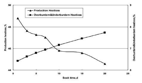
Figure 2. Optimization of Soaking Time
After injecting heat inside the reservoir, well is shut for a specific period, and this period is called soaking time. As seen above optimum soaking time is important because if soaked for a longer period of time, the heat drainage radius increases, but at the same time heat loss to overburden and under burden formation also increases. In this design study, a steam injection rate of 200 m3 /d with a bottom hole steam quality of approximately 60% and a steam injection strength of 160 m3/m has been modelled for various soaking periods. Figure 3 shows the steam quality during injection.
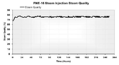
Figure 3. Steam Quality During Injection
"Steam quality" means the maximum temperature present at the bell mouth. As seen above, the quality of the steam has been kept consistent throughout the period of injection. CSS requires the combustion of approximately 1 Billion Barrels of Petroleum Liquid (BBL) of oil to be burned to produce 3-4 BBL of oil. Therefore, it becomes necessary to maintain steam quality.
Elbaloula and Musa (2018) describe and analyze the CSS concerns and challenges in Sudanese oil fields, such as depth limitation greater than 1400 m, conventional completion wells, and comingle injection and production.
The results demonstrate the great success of thermal EOR projects, which nearly doubled output from 130 barrels per day to 300 barrels per day in the FNE oil field and from 280 barrels per day to 440 barrels per day in the bamboo oil field.
It is strongly advised to choose shallow depth, thermal completion, prevent comingle layer injection, or employ a unique technique for separate layer injection in order to achieve the most recovery out of the wells.
CSS have been implemented in Sudan since 2009, with the FNE oil field being the first to do so; the field contains heavy oil in multiple reservoirs of the bentiu formation in 8 selected wells spread across the field and is led to maximize the recovery factor; the actual result is better than predicted in simulation studies, with a lower steam intensity of 120 m/m compared to the planned 160 m/m (Tewari et al., 2011). Also, Elbaloula and Musa (2018) studied the sudanese oil field and designed and implemented Africa's first steam flooding pilot test, and the results showed that switching from Cyclic Steam Stimulation (CSS) to steam flooding after the third cycle could increase the field's recovery factor by up to 43 to 50.1%, whereas CSS could only increase the recovery percent of the suggested well groups by 32.5 to 34.2% of the studied sector model, making steam flooding a more appealing method as a development method (Elbaloula & Musa, 2018). In the heavy oil fields of Sudan, this field contains heavy oil in multiple reservoirs of the bentiu formation. This 18-20% primary recovery plan is designed for early thermal enhanced oil recovery applications to maximize recovery.
The geological data, reservoir data, and production data for the heavy oil Sudanese field have been collected and used for analysis to investigate the main challenge of CSS and to design the optimum selection criteria that can maximize the recovery factor. The reservoir properties (i.e., porosity, permeability, depth, initial formation pressure, etc.) have been analyzed. When we compare the performance of the cold wells and the CSS in the same well, it has been found that the production increased to almost double for the first cycle, 70% for the second cycle, and 50% in the third cycle, and the production returned to being the same as cold after the fourth cycle for most wells (Elbaloula & Musa, 2018). The CSS challenges in heavy oil Sudanese fields are depth limitation more than 1400 m, horizontal wells, high water cuts, conventional completion wells, and a long soaking period.
Clark et al. (2010) developed a method for improving the Steam injection and production conformance in thermal EOR work using intelligent well technology consisting Interval Control Valves (ICV), well segmentation and associated borehole instrumentation and that is nodal analysis. The biggest hurdle in the process of Steam Assisted Gravity Drainage (SAGD) is achieving even steam conformance along the horizontal wellbore because of many reasons like reservoir heterogeneity and the limited control of steam placement along the wellbore. Figure 4 depicts the SAGD wells with steam trap or steam control in conjunction with the production well.
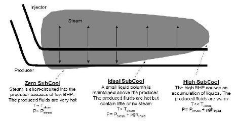
Figure 4. SAGD Wells Commonly Handled Under Steam Trap or Sub Cool Control With the Production Well is Clogged Again if Active Steam Reaches the Producer
To achieve the desired results, a number of technologies were applied, including dual tubing strings and the relocation of a tubing string along the wellbore. However, due to high heterogeneity, it was concluded that the better option was the use of ICV, which would allow for some measure of segmentation and control from the surface, which eventually helped to develop stepped rate control (Clark et al., 2010). The trial injector's intelligent ICV completion is shown in Figure 5.
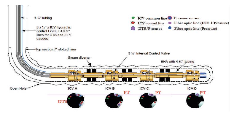
Figure 5. Trial Injector Intelligent ICV Completion
The modelling that had been done shows that depending on the magnitude of the heterogeneity present in the reservoir, an improvement of 20 to 40% in the steam oil ratio and 5-10% in recovery can be achieved in a SAGD method when both injection conformance and producer differential steam trap control can be applied in a zonal horizontal well.
The three types of EOR are chemical flooding, gas injection, and thermal. Chemical Enhanced Oil Recovery (CEOR) has been determined to be an effective oil recovery technique for recovering bypassed oil and residual oil trapped in reservoirs. This EOR method relies on the injection of chemicals to boost oil recovery. Gas injection, uses gases such as natural gas, nitrogen, or carbon dioxide (CO2) that expand in a reservoir to push additional oil to a production wellbore, or other gases that dissolve in the oil to lower its viscosity and improve its flow rate. Thermal recovery is an EOR technique that has been commercially successful. Conventionally, thermal EOR usually involves burning natural gas to produce steam, which is injected into the reservoir to heat heavy oil to reduce its viscosity.
Thermal EOR is basically introducing heat energy inside the oil reservoir to lower the viscosity and density of the oil, which helps improve the mobility of the oil. Since most of the oil left is heavier, thermal EOR has been found to be the most successful EOR method worldwide. In the USA, from 1980–2002, over 4 Billion Barrels of Petroleum Liquid (BBL) of oil were recovered using the steam flooding method. Thermal Enhanced Oil Recovery (TEOR) can be used in light oil reservoirs despite its usefulness in heavy oil deposits. TEOR is perhaps the most effective EOR technique for up surging output, particularly steam flooding, while having a far larger environmental impact than traditional oil production.
Thermal recovery has a long history that dates to 1865, but the first TEOR experiment that had a substantial industrial impact was carried out in 1931, not far from Woodson, Texas. This test included steam injection. When reservoir fluid pressure was released by a retrograde flow of injected steam, an advanced steam injection (cyclic steam injection) was subsequently identified ironically, which produced a significant amount of oil instead of the anticipated steam. Subsequent large-scale TEOR projects were conducted in the Tia Juana and Mene' Grande fields, both located in Venezuela. When the venezuelan field (Mene Grande) was discovered, steam flooding was chosen as the best TEOR method, and a continuous steam injection over several weeks was deployed, with the wells shut in for short periods to support heat transfer within the reservoir. Figure 6 shows the production of thermal EOR.
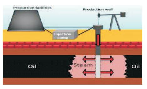
Figure 6. Thermal EOR
Based on Figure 7, the classification of thermal EOR is divided into the hot fluid injection process and the In-Situ Combustion (ISC) process. For our analysis, the ISC process is considered.
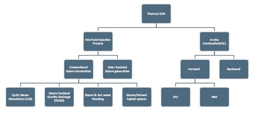
Figure 7. Classification of Thermal EOR
In situ combustion, also known as fire flooding, is a unique type of EOR process because some of the oil-in-place is oxidized and utilized as a fuel to produce heat. In the insitu combustion process, the reservoir's crude oil is set ablaze, and air injection maintains the flames. In the middle of the procedure, air is continuously injected into an injection well to start it. After air has been introduced for a while, the crude oil in the reservoir may ignite spontaneously or it may require heating. Even without burning, heat is produced by a chemical interaction between the oxygen in the air and the crude oil. Depending on the nature of the crude, the pace of this oxidation process can be enough to raise temperatures high enough to ignite the oil. If not, ignition can be initiated by the down-hole electric heaters, preheating injection air, and preceding air injection with oxidizable chemicals. There are three forms of in situ combustion processes, namely forward combustion, wet combustion, and backward combustion.
The term "forward combustion" is used to signify the fact that the flame front is advancing in the same direction as the injected air. The schematic view of several distinct zones formed in an oil reservoir during the forward combustion process is shown in Figure 8.
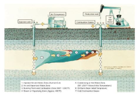
Figure 8. A Schematic View of Several Distinct Zones Formed in An Oil-Reservoir During The Forward Combustion Process
In the forward combustion, the dry combustion is considered with the analysis for the final showdown. The oil displacement mechanism and temperature profile associated with each of these zones are depicted in Figure 9.
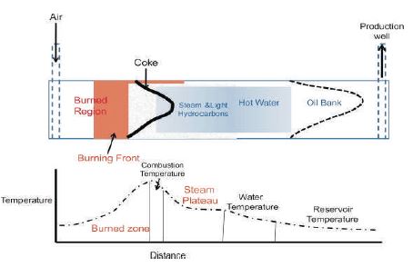
Figure 9. The Oil Displacement Mechanism and Temperature Profile Associated with Each of these Zones
As shown in both Figures 8 and 9, there are seven zones that have been recognized during the forward combustion process, and the zones are described briefly.
The burned zone is the zone that has already been burned. This zone is devoid of any oil or coke, and it may also include a tiny quantity of leftover, unburned organic compounds. However, it is mostly made up of pure sand. The burnt zone temperature rises from the injected air temperature at the injector to the temperature at the combustion leading edge as a result of the continuous air injection. The combustion front zone is ahead of the burned-out zone and has a temperature variation ranging from 600 °F to 1200 °F. It is in this region that oxygen combines with fuel and high-temperature oxidation occurs. Considering the coke zone, the coke region is located directly in front of the combustion front zone. The zone where carbonaceous material has been deposited as a result of the thermal cracking of the crude oil is represented by the coke area.
High-molecular-weight and high- boiling- point components make up the coke residual fractions. These fractions can represent up to 20% of the crude oil. The vaporizing zone, which includes evaporated light hydrocarbons, combustion by-products, and steam, is located before the coke area. The temperature range in this region ranges from that required to evaporate reservoir condensed water to the high temperature of combustion.
Then the condensing zone is located farther downstream of the vaporizing region and is where oil is removed by several driving forces. Condensed steam generates a hot water flood mechanism, and condensed light hydrocarbons displace reservoir oil that is miscible, and combustion gases enable further oil recovery via gas drive. Temperatures in this zone are typically 50°F–200°F above the initial reservoir temperature. While in the oil bank zone, the displaced oil builds up to create an oil bank. With a slight improvement in oil viscosity, the temperature in the zone is practically close to the initial reservoir temperature. Finally, the undisturbed reservoir is given by the portion of the reservoir that has not been disturbed and has not been impacted by combustion and is located further in front of the oil bank.
Since air has a low heat-carrying capacity, the forward combustion process uses heat relatively inefficiently. In the forward combustion system, only around 20% of the heat produced is transferred ahead of the combustion front, where it is helpful for oil recovery. The charred area is where the leftover heat is kept and is eventually lost to the cap and base rock of the pay zone. Several variations of the in-situ process have been proposed to utilize this lost heat. Water may be injected simultaneously or alternately with air, resulting in better heat distribution and reduced air requirements. In the burned zone, injected water is converted to superheated steam, which flows through the flame and heats the reservoir ahead. This is called Combination of Forward Combustion and Water Flood (COFCAW) process.
It has been recommended that the reserve combustion method be used in reservoirs that house very viscous crude oil systems. The reverse combustion process is initiated as a forward combustion process by pumping air into a well that will eventually be converted into a producer. The well is placed into production, and air injection is shifted to another nearby well after establishing ignition and burning out a short distance in the oil sand. While the combustion front moves in the opposite direction toward the air injection well, the oil is displaced toward the producing well by the air injection in the nearby well as it passes through the hot zone. The air (i.e., oxygen supply) is shut off and the air injection well is shut off if the oil near the air injection well ignites spontaneously.
The in-situ combustion process tends to sweep only the upper part of the oil zone; therefore, vertical sweep in very thick formations is likely to be poor. The burning front produces steam both by evaporating the interstitial water and by combustion reactions. The steam mobilizes and displaces much of the heavy oil ahead of the front, but when water condenses from the steam, it settles below the steam vapors and combustion gases, thus causing their flow to concentrate in the upper part of the oil zone. The oil-bearing layers, interbedded shale, base rock, and cap rock are heated to a greater extent than the oil itself by the heat produced by in-situ combustion. As a result, in situ combustion would be practical from an economic standpoint when there is less rock to heat, i.e., when the porosity and oil saturations are high and the sand thickness is modest.
Thermal infusion is a cycle that is regularly utilized in the oil and gas industry to work with oil extraction. During the warm infusion process, heat is introduced to the oil to decrease its consistency. Warm infusions can be carried out using either warmed liquids or flammable gases. The infusion of intensity-bearing liquid might offer a more extensive application to optional and tertiary recuperation from regular oil supplies than underground burning since the cycle is more easily controlled and the repository prerequisites, as a rule, are less basic. Conduction heat misfortunes to overburden and under burden will always impose a monetary limit on the size of the area that can be cleared out from any one infusion point for any random set of conditions (Bai & Bai, 2018; Corrosionpedia, n.d.).
Steam generators are utilized to deliver steam for the steam flood. The most well-known steam generators are the 25-and 50-Metric Million British Thermal Unit/hour (MMBtu/hr.) units. The 25- MMBtu/hr. units are utilized as versatile units and give steam to cyclic-steaming or remote-infusion wells. The 50-MMBtu/hr. units give steam from a focal banked area, which works on the water- and fuel-treatment plants and the steam-circulation framework. If fume gas cleaning is required, the scrubber framework can also be concentrated. Critical reserve funds can be acknowledged by bringing together these units.
An ordinary steam generator and framework stream schematic are displayed in Figures 6 and 7. It consists of a convection segment and a brilliant segment. The convection segment is intended to preheat the mellowed feed water, and the radiant area further warms the steam pipe for producing steam. A steam generator produces 60 to 80% quality steam, contingent upon the repository's necessities. More excellent steam can be created if great-quality water and fuel gas are utilized. At the point when the expected steam quality exceeds 90%, control becomes troublesome, and the opportunity of an overheated pipe builds in view of the generally low fluid stage close to the line emanating (Wikipedia, 2022).
CSS is also known as the "huff and puff method," an alternate injection of steam and production of oil from the same well. This consists of three stages, the first of which is the injection of high-pressure steam under high pressure and temperature into the pay zone to mobilize oil and build reservoir pressure over a period of several months. Soaking period, also called "soak stage," is when a well is shut in for a period of 3-6 days depending on the reservoir parameters to allow injected heat to distribute inside the reservoir. Finally the production of oil is started and initial production rate are increased for short period and then decline gradually as the production goes along. The schematic illustration of CSS is shown in Figure 10.
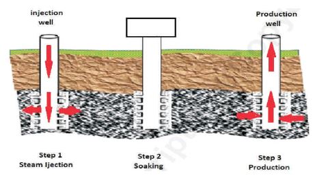
Figure 10. Schematic Illustration of CSS
In the case of SAGD, steam at high pressure is continuously injected into a horizontal well to provide thermal energy in the well that reduces the oil's viscosity. The heated well is then drained into a lower well, where it is pumped out as shown in Figure 11. This method is best suited for heavy oil extraction in carbonate reservoirs, as reported by Hosseini et al. (2017).
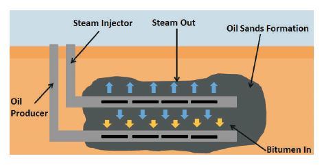
Figure 11. Schematic Illustration of Steam-Assisted Gravity Drainage Process
A strategy for warm recuperation is where hot water is infused into a supply through extraordinarily circulated infusion wells. Hot water flooding diminishes the thickness of the unrefined petroleum, permitting it to move more effectively toward the creation wells. Hot water flooding, otherwise called boiling water infusion, is ordinarily less powerful than a steam-infusion process since water has a lower heat content than steam. All things considered, it is best under specific circumstances, for example, development aversion to new water (Schlumberger, n.d.).
Gaseous EOR is more commonly used in tight oil reservoirs, such as shale oil, where the permeability to flow oil is low and economically unfeasible. In many gas flooding projects performed in the field, the miscibility of the gas injected is usually the most desired displacement mechanism. Gas injection (miscible and immiscible) improves microscopic displacement efficiency by reducing the Inter Facial Tension (IFT) between the oil and the displacing gas fluid. When used after a flood, the injected gas helps in re-establishing a pathway for the remaining residual oil to flow through the rock space, which then leads to low residual oil saturation. The reservoir conditions, as well as local availability, would influence what type of gas is most likely to be injected in the reservoir. CO, for instance, is miscible with oil at a relatively low pressure and temperature (shallow reservoirs) and is readily available. In sandstone reservoirs, CO injection is best suited for light to medium oils (>30° American Petroleum Institute (API)). Most CO flooding field projects are being conducted in the United States and Canada. Figure 12 shows the schematic view of gaseous EOR.
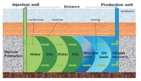
Figure 12. Schematic View of Gaseous EOR
By capturing CO2 at the site of combustion and storing it in geological reservoirs or through Enhanced Oil Recovery (EOR) in a process known as "miscible flooding," carbon capture seeks to minimize the release of CO2 and lower CO2 atmospheric emissions. Supercritical CO2 is used in miscible CO-EOR to remove oil from a depleted oil reservoir. By dissolving in, swelling, and lowering the viscosity of the oil, CO2 increases oil recovery. Natural gas and flue gas are examples of hydrocarbon gases that are employed in certain large reservoirs to replace miscible oil. It's possible that these displacements in the reservoir are just "pressure maintenance." In these flooding procedures, the ideal injection parameters are defined by the minimal miscibility pressure, which is established by several contact studies and swelling tests.
The decision of whether the CO2 should be miscible or immiscible depends on several variables, primarily the qualities of the reservoir rock and reservoir fluid, such as the pay zone depth, thickness, and mineralogy. The general rule is that when miscibility is challenging to obtain, as it is with moderately to severely viscous oils, immiscible CO2 becomes extremely valuable. One of the most important interactions between the gas and the oil that takes place when the immiscible CO2 is introduced into the reservoir is CO2 solubility. Oil will start to expand as a result of CO2 diffusing into it during solubility. Depending on the composition and other characteristics of the crude oil, such as its API gravity and molecular weight, it will have a varied solubility. The thermodynamics of the reservoir is a significant factor that has been proven to affect CO2 solubility in crude oil. While raising the temperature will result in a drop in solubility since the CO2 molecules have a much higher activity at higher temperatures, increasing the CO2 injection pressure will result in a higher solubility. Due to the high solubility of CO2 in crude oil during immiscible CO2 injection, this application can have a strong influence on increasing oil recovery, even in heavy oil reservoirs. Even though solubility has been proven to be an extremely important factor during immiscible CO2 injection, no comprehensive data analysis has yet been performed to determine its overall impact on different crude oils from lab and field studies.
Nitrogen is used as the injection fluid for EOR and is widely used in oil field operations. In miscible gas injection, the gas is injected at or above the Minimum Miscibility Pressure (MMP), which causes the gas to be miscible in oil. MMP of various oils varies with temperature, reservoir fluid composition, and pressure on miscibility. Here, the nitrogen injection process and the determination of nitrogen MMP are discussed (Al-Anazi, 2007).
Among all the EOR strategies, the chemical EOR strategy, a non-thermal EOR technique, has been pronounced as the most encouraging due to its higher productivity, specialized financial plausibility, and sensible capital expense.
Chemical EOR (CEOR) techniques, and even more explicitly polymer flooding, were most well-known during the 1980s, yet from that point forward, their prevalence consistently declined. By the by, polymer and surfactant flooding are among the most commonly utilized CEOR strategies. In any case, these techniques are profoundly delicate due to the unpredictability of oil costs, regardless of the improvement of additional effective and less expensive surfactants and polymers. There are a few large-scale projects underway, including polymer flooding in Argentina, Canada, China, India, and the US. Other CEOR strategies, like the infusion of surfactant, alkali, alkali polymer, alkali surfactant-polymer, and surfactant-polymer, as well as micelle solutions, have been tried, however, on just a set number of fields. Consequently, the absence of adequate information on the fruitful utilization of these sorts of synthetic compounds for CEOR limits their application because of their likely eccentricity.
The three compounds that stand out in typical EOR are polymers, alkalis, and surfactants. The viscosity of the aqueous phase is increased by the injection of polymers using water floods, which also enhances their mobility as they migrate from the injection well toward the producer. The polymer solution also improves oil recovery by decreasing the reservoir's permeability to water.
Surfactant solutions work by interacting with certain components in crude oil, solubilizing interfacial coatings, and inducing emulsification to lower the IFT between water and crude oil. The capillary forces of trapped and leftover oil are reduced as a result of the IFT decrease. Additionally, surfactant adsorption on reservoir rocks alters the wettability of the rocks, increasing oil recovery. While using a different injectant, alkali flooding works in the same way that surfactant solutions do. Foam flooding guarantees the pore scale and sweep efficiency of the Original Oil In Place (OOIP) (Levitt & Pope, 2008).
During a water flood, polymer flooding is used as a mobility control agent with the aim of improving volumetric sweep and displacement efficiency. At a lower risk and for a wider variety of reservoir conditions, polymer injection operations are significantly more prevalent than chemical floods, although they produce comparatively little additional oil. The range of recovery with polymer is 5–30% of OOIP (Courtenay, France). Polymer flood efficiency is in the range of 0.7 to 1.75 lb of polymer per bbl of incremental oil production.
Gas injection is a common and widely applied method for enhanced oil recovery (EOR). However, because of high gas mobility, recovery factors obtained during gas injection are often lower than anticipated, as gas tends to override the water and Oil In Place (OIP). Water-Alternating Gas (WAG) Injection, that is, the injection of gas slugs alternated with slugs of water, has been successfully applied to partially overcome the drawbacks of continuous gas injection. Foaming the gas is another method for reducing gas mobility and increasing volumetric sweep efficiency. Foam involves a discontinuous gas phase where gas bubbles form within a continuous liquid phase. Gravity segregation might also occur during WAG flooding, yielding an early breakthrough of gas. Gas injection is a common and widely applied method for Enhanced Oil Recovery (EOR). However, because of high gas mobility, recovery factors obtained during gas injection are often lower than anticipated as gas tends to override the water and Oil In Place (OIP) (Janssen et al., 2019).
Chemical EOR with surfactant flooding is a tried-and-true technique. This approach has been effective because it maximizes oil recovery by using several different processes. These include emulsification, foam production, wettability modification, and an Inter Facial Tension (IFT) decrease. Surfactant flooding continues to face difficulties, such as instability under hard or typical reservoir conditions and high adsorption. These problems have an impact on the anticipated oil recovery, which lowers the projects' economic returns. Nevertheless, surfactants can be correctly chosen based on the characteristics of the reservoir and the kind of rock. Surfactant screening techniques are typically used for this, and they place restrictions on the IFT, surfactant adsorption, and other parameters under certain temperature and salinity conditions (Massarweh & Abushaikha, 2020).
One of the key techniques in chemically enhanced oil recovery is the alkaline flooding process, which involves Chemical Enhanced Oil Recovery (CEOR). When an alkaline agent reacts with acidic components in crude oil, alkaline flooding creates an in-situ surfactant in the reservoir. Alkaline water flooding's primary goal is to mobilize unrecovered oil in porous media by improving the effectiveness of the microscopic sweep. Sodium hydroxide, sodium carbonate, sodium orthosilicate, sodium tripolyphosphate, ammonium hydroxyl, and ammonium carbonate are alkalis utilized in alkaline related EOR. This triggers several processes aimed at enhancing oil recovery (Sheng, 2013).
Apart from thermal, gaseous, and chemical EOR techniques, there are some other techniques used to enhance the recovery of oil in place that is left after the primary and secondary oil recovery techniques. There are several methods, namely Microbial Enhanced Oil Recovery (MEOR), alternated injection of water and gas, water injection at the gas-oil interface, explosives, and vibrations.
MEOR is an alternate strategy for oil recovery. MEOR frequently entails injecting vital nutrients and living microorganisms into an injection well. The injected microorganisms multiply exponentially in the presence of favorable environmental conditions in the reservoir, and the metabolic products of these bacteria mobilize the leftover oil. The illustration of MEOR is shown in Figure 13. The injected microorganisms can produce a selection of metabolic products that find useful applications in EOR. The growth of the microorganisms and their effects depend on a number of factors, including for starters, the reservoir's pressure, porosity, and permeability, temperature, pH, dissolved solids, and salinity. Secondly, the availability of nutrients to the bacteria. Thirdly, the specific type of microorganisms injected into the reservoir.
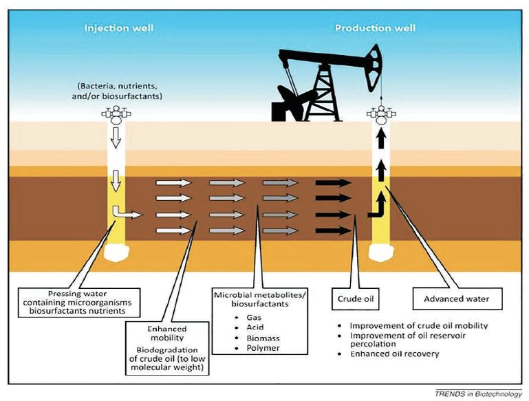
Figure 13. Illustration MEOR
After primary and secondary recovery techniques have been used, all of the remaining oil in a reservoir is thought to be recoverable by MEOR to a maximum of 50%. In general, the microbial growth and metabolites generated are used to modify the chemical and physical features of reservoir rocks and crude oil in order to achieve this extra recovery.
Therefore, MEOR might circumvent the basic barriers to effective oil recovery, such as high crude oil viscosity, poor reservoir permeability, and high oil-water IFTs that cause capillary forces that are sufficiently strong to keep the oil in the reservoir rock's pores.
The oil and gas industry has been interested in the relatively advanced Water Alternating Gas (WAG) injection oil recovery method used in hydrocarbon reservoirs for a long time due to its good performance. By fusing the advantages of Gas Injection (GI) and Water Flooding (WF), the major objective of the WAG projects is to manage mobility and reduce the problem of viscous fingering, resulting in better oil recovery through WF. A thorough awareness of prior successful and unsuccessful experiences, as well as a sufficient comprehension of the technical and non-technical parts of the recovery process, are necessary for the implementation of a new EOR or IOR project. Examining comparable initiatives that have been described in the literature can provide this insight. In tertiary EOR techniques, the WAG method is a frequently used and recognized procedure. 59 WAG projects were reviewed from different locations. They showed that about 5–10% of the Original Oil In Place (OOIP) was recovered in successful WAG projects after secondary EOR methods. They stated that the majority of WAG projects were carried out as a miscible process in onshore sandstone reservoirs (Afzali et al., 2018).
The potential of the thermal recovery process is much greater than the current production would suggest. One reason is that there are large accumulations of heavy crudes amenable to thermal recovery in certain parts of the world, especially in western Canada and central Venezuela. Another potential of thermal recovery is that it can be used to displace and recover light crudes.
Steam injection is challenged by factors including access to inexpensive and clean-burning fuel to generate steam, water for steam generation, energy intensity that increases life-cycle CO2emissions, air pollution, and ultimately public acceptance. These are considerable environmental challenges (Kovscek, 2012).
Formation of oil-water emulsions, which cause pumping problems and reduce well productivity, production of lowpH (acidic) hot water rich in sulphate and iron that causes corrosion problems, increased sand production, and cave-ins Wax and asphaltene formation as a result of oil thermal cracking, liner and tubing failure due to high temperatures at production are disadvantages (Ahmed & Meehan, 2012).
Matrix permeability, oil viscosity, and oil-gas capillary pressure are the pinnacles that affect the Thermally Assisted Gas Oil Gravity Drainage (TAGOGD) process. The requirement for sufficient fractures to sustain the drainage process is a natural limitation in the selection process. Steam flooding-based technologies were recommended due to their power to increase the recovery factor in heavy and extra-heavy oil reservoirs by providing the required heat content of steam. Transitional producer wells are a proven well design concept for production closer to the heating zone. Viscosity is one of the parameters with high uncertainty in heavy and extra-heavy oils. It should be said that EOR technologies based on steam injection show potential to be used in 46.8% of the OOIP in sands with CSS and SAGD.
The potential of thermal recovery processes is much greater than the current production would suggest. One reason is that there are large accumulations of heavy crudes (some of which are called tar sands) that are amenable to thermal recovery in certain parts of the world, especially in western Canada and central Venezuela. The amount of crude in place in those two areas is estimated at about 950 x 10 BBL for Canada (19) and 750 x 109 BBL for Venezuela (22). Only a fraction of those amounts ultimately will be proved as reserves. For comparison, the proved reserves for the world as of the end of 1975 were 567 x 109 BBL (23). Thermal recovery is expected to play a dominant role in the production of those reserves.
The fact that some of the other enhanced recovery processes have not reached the maturity of thermal recovery, the pressures that exist to increase oil production in the U.S., and the recognition that thermal processes may be used today to supplement primary methods for increasing U.S. oil production should accelerate the early commercial use of thermal recovery in light-crude reservoirs. In such applications, the production rates are increased because the total field operating life is reduced and less oil is left in the reservoir at the end of the project.
The number of light-oil reservoirs in which thermal recovery may be economically attractive is probably small, although this may change with experience (Prats, 1982).