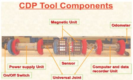
Figure 1. Different CDP Tool Components
Pigging is commonly utilized in pipelines for different maintenance tasks such as cleaning and inspecting pipes using pigging pigs. This is done without interrupting the flow of goods via the pipeline. The operation is carried out by introducing a pig from the source to the end-point of the pipeline. During the pig's travel through the pipeline, it brushes out the trapped product and cleans the pipe walls. It is also utilized for pipeline inspection, providing us with interior data such as corrosion characteristics, and identifying dents, wrinkles, buckles, welding faults, and fractures. It ensures product flow and reduces product contamination within the pipeline. It eliminates accumulated debris, which eventually helps to defend against the defects with heavy duty bristles and pit cleaning brushes are highly effective in both swiping the liquids downstream, and out of pits.
The use of pipeline inspection gauges or pigs, i.e., pigging, is necessary to execute different operations on a pipeline without interrupting the flow of goods (Tolmasquim & Nieckele, 2008). These procedures include pipeline cleaning and inspection. This is done by placing the pig in a "pig launcher" (or launching station). The launcher or launching station is then shut off, and the pressure of the GAS or Liquefied Petroleum Gas (LPG) in the pipeline is employed to propel it along the pipeline until it reaches the receiving trap, the "pig catcher" (or receiving station) (Quarini & Shire, 2007). Modern intelligent pigs are very sophisticated devices with varying degrees of sophistication and complexity depending on their intended function and manufacturer. An intelligent pig is essentially a computer that collects various types of data while travelling around the forest.
The first pigging operation took place in 1870. The first use of rubber ball pigging was done in 1904. The development of foam pigs took place in 1960. The development of the high-resolution inspection tool happened in the 1970s. The development of ultrasonic tools was done in the 1980s.
For more than half a century, pigs consisted of steel bodies and rubber, leather, or urethane cups or discs. The tools were equipped with wire brushes, scrapers, knife blades, and other devices for ploughing. Until 1960, most pipe cleaning was limited to the oil and gas industry. Then the foam bullet-shaped pig was developed—referred to as the "polly" pig because it was made of polyurethane foam. Although the oil and gas industry remains the largest user of foam pigs, many new industries, such as the water and wastewater industry, as well as the chemical processing, petrochemical, and mining industries, are now using pigs in their pipelines, realizing gains such as energy savings, increased flows, decreased pumping pressures, cleaner products, and salvaged products.
The lessons learned from standard pigging operations to clean, dewater, fill, and displace product from pipelines and the pressures, speeds, and problems incurred have greatly contributed to the development of instrumented pigs. These were introduced in the late 1960s, and development is continuing to the present day.
Quarini and Shire (2007) depicts some background on pigs and explain why pigging systems are used as well as why they are not. A review presents the different types of pigs, their functions, and their features. The most common types of pigs are considered as well as some of the specialist pigs that have been designed for specific tasks. Also covered is the more recent development of nonsolid pigs, which include gel pigs for use in the hydrocarbon industries and ice pigs for use in the fluid products and process industries.
Tolmasquim and Nieckele (2008) provide an efficient tool to assist in the control and design of pig operations through pipelines; a numerical code has been developed based on a finite difference scheme. It allows the simulation of two-fluid transient flow, i.e., liquid–liquid, gas–gas, or liquid–gas products in the pipeline. Modules to automatically control process variables were included to employ different strategies to reach an efficient operation.
Cameron et al. (2008) discussed regulations and issues related to pigging and pipeline integrity management programs. Methods of cleaning pigs and determining flow regimes were also reviewed. Pigging incidents have caused injuries to oil and gas personnel. Documented procedures must be followed in order to ensure the safety of operators. Regulatory oversight programmes are used to evaluate the adequacy and effectiveness of integrity management programmes as well as to determine their effectiveness. There are currently over 500 different types of pigs on the market, and the appropriate pigs must be considered in terms of acid gas corrosion, under deposit corrosion, and microbiologically induced corrosion.
Mishra et al. (2019) mention that crude oil is continuously flowing in deeply buried cross-country pipelines containing slugs and wax, which get deposited within the pipeline, creating a blockage, and the situation gets even worse due to the presence of corrosion and erosion because of them. In this research, we have focused on the details of a pipe inspection gauge robot that can be used for cleaning and leakage detection of cross-country pipelines that run with the current of crude oil within the buried pipelines.
Clark and Nestleroth (2004) depict that pigs that are equipped with sensors and data recording devices are called "intelligent pigs." Pipelines that cannot be inspected using intelligent pigs are deemed "unpigable." But many factors affect the passage of a pig through a pipeline, or its "pigability." The pigability pipeline extends well beyond the basic need for a long, round hole with a means to enter and exit. An accurate assessment of pigability includes consideration of pipeline length, attributes, pressure, flow rate, deformation, cleanliness, and other factors, as well as the availability of inspection technology.
The factors that are considered for pigging are the condition of the pipe, the design basis of the pipeline, the number and type of bends, the pipeline elevation, and the frequency of pigging.
Additional considerations such as number and type of bends, number and type of valves, internal diameter(s), end connections, flow rate, flow media, pressure rating, operating temperature, pipeline length, pipeline elevations, handling of flow and debris downstream, and other factors are considered.
Pressure requirements are considered for moving the pig through piping. Product variables that can affect pressure requirements, such as viscosity and density, ability of the pig to move through the piping layout with the clean-inplace requirements are considered.
It is also based on the number of bends and the type of bends, which mainly affect the experiment as a factor, and also on the economic condition of the experiment based on certain conditions. The use of bends is economic as it reduces the number of expensive fittings.
Given the pipeline elevation and frequency, it has a significant impact. Because elevation is important in cleaning and the effective removal of impurities.
Pigs are used to clean solids, scale, wax buildup, and other debris from the pipelines to keep the pipeline flow efficiency high.
In pipeline transportation, pigging is the practice of using pipeline inspection gauges or gadgets, devices generally referred to as "pigs" or "scrapers." The intelligent PIG is used to inspect the pipeline wall defects (corrosion, dents, cracks, pits, and so on) and implement pipeline surveying.
To remove undesirable materials, Internal cleaning, various cleaning, clearing, maintenance, and inspection of pipelines are all performed.
Cleaning pigs is one of the most efficient tools for cleaning the pipeline. Impurities such as silica/mud, oil and grease, ferrous particles, and so on are deposited inside pipeline walls over time (Davidson, 2002). These materials can cause internal corrosion. So, the pipelines are to be cleaned as per some pre-defined schedule and guidelines. Many types of cleaning Pigs are used in the pipeline industry (Clark & Nestleroth, 2004). The industry generally uses Bi-Di brushes and magnetic pigs to clean the pipelines. The brush pigs rub the pipeline surface, and their sealing discs collect the debris, whereas the magnetic pig collects the ferrous particles along with other materials. It increases pipeline efficiencies (Ran et al., 2013).
Utility pigs are used to clean the pipeline of debris or unwanted materials. Debris can be accumulated during pipeline construction and during the operating phase. Types of utility pigs include mandrel pigs, foam pigs, solidcast pigs, and spherical pigs.
The mandrel pig can be used for cleaning, sealing, or a combination of both. The seals and brushes can be replaced to make the pig reusable. These pigs are designed for long runs. The cost of redressing the pig is high, and larger pigs require special handling equipment to load and unload the pig. Occasionally, the wire brush bristles break off and get into instrumentation and other unwanted places. Smaller-size mandrel pigs do not negotiate 1.5 degree bends.
The Foam Pig is initially launched to test the pig's ability and pipeline cleanliness, as well as to verify the internal geometry of the pipeline in terms of ovality, dent, and so on, and to ensure that internal bore restriction at any location does not exceed the limits of the proposed tools to be used later (Deng et al., 2017).The pig can manoeuvre itself through 1.5 degree bends. It can be classified into three groups based on density range (Weight/Volume Ratio) as low density: - 1-4lb/Cu. Ft, medium density: - 5-7lb/Cu. Ft, high density: - 8-10lb/Cu. Ft
Solid-cast pigs are usually molded in one piece. The materials used for the preparation of solid cast pigs are neoprene, nitrile, Viton, and polyurethane. Solid-cast pigs are considered sealing pigs, although some solid-cast pigs are available with wraparound brushes and can be used for cleaning purposes. The cup, disc, and combination cup/disc solid cast pig are all in available design. Because of the cost to redress a mandrel pig, many companies use the solid-cast pig up to 14 inches or 16 inches. Solid-cast pigs are used in removing liquids from product pipelines, removing condensate and water from wet gas systems, and controlling paraffin buildup in crude oil systems.
Spherical PIGs are normally used for removing liquids from wet gas systems serving to prove fluid meters. They are also used in controlling paraffin in crude oil pipelines flooding the pipeline to conduct hydrostatic tests, dewatering after pipeline rehabilitation or after new construction. They should never be run in lanes that do not have special flow tees installed.
To perform internal surveys such as dents, wrinkles, ovality, internal corrosion, cracks, crack-like defects, longitudinal weld defects, metal loss, etc. incline inspection pigs are used. The type of information gathered by inspection pigs includes temperature and pressure, corrosion and metal loss, diameter, bends and curvature, cracks, weld defects, surface pitting, and areas of crushing and deformation. Inspection pigs use two methods to gather information about the interior condition of the pipeline.
Gel pigs (a combination of gelled liquids) can be used in conjunction with conventional pigs or by themselves. Pumped through the pipeline, there are a number of uses for gel pigs, including product separation, debris removal, hydrostatic testing, condensate removal, and removing a stuck pig. It is used in conjunction with conventional pigs to optimize pipeline dewatering product separation.
A plug is a specialized pig that can be used to isolate a section of pipeline while it is under pressure for repair. It is to isolate a section of the pipeline under pressure.
The gauge pig has an aluminum gauge plate covering approximately 95% of the minimum ID of the pipeline and is launched to see if there is any hard dent observed in the gauge plate. Depending on the severity of the damage to the gauge plate after receiving the gauge pig, a subsequent pigging operation is planned. The discs are made of polyurethane with a carbon steel body (Mishra et al., 2019). The pig is suitable for a 250-kilometer continuous run. The pig can manoeuvre itself through 3D bends. Pig is willing to negotiate ID restrictions of up to 15%.The pig can withstand temperatures ranging from 0 degrees to 80 degrees.
The cleaning pig, which has a brush and magnet, is launched to clean the pipe by removing the non-ferrous and ferrous debris left during construction or operation. The ferric debris includes the welding rods, nuts, brushes, and various solid steel objects. The pig is bi-directional, with the housing having adequate strength to prevent the magnet from breaking and falling into pieces in the event of contact. Each magnet can lift approximately 3 kilos and has an 800 gauss strength. The pig can manoeuvre through 3D bends.
Two types of Incline inspection pig are as follows,
Geometrical Pig - It determines the dents, wrinkles, ovality, bend radius and angle etc.
Intelligent Pig - It determines pitting corrosion, general corrosion, wall thinning, mechanical damage, girth weld corrosion, dents and pipe wall thickness < a href="#ref1"> (Cameron et al., 2008).
There are different types of Intelligent Pig. The Magnetic Flux Leakage (MFL) are of two types namely corrosion detection pig and axial detection pig.
The various tools used for the Pigging process is defined as follows.
One of the most efficient ways to gather the information that may serve as the cornerstone of an integrity management programme is through in-line inspection (also known as "intelligent pigging") programs. Several ILI tool types can identify different pipeline flaws, but highresolution MFL tools are becoming more common as their uses expand beyond those for which they were originally intended. The modern, high-resolution MFL instrument, which is intended for locating regions of metal loss, can precisely determine the degree of corrosion characteristics and characterize dents, wrinkles, buckles, welding faults, and fractures.
Based on the thickness of the metal loss due to corrosion or due to other reasons, the assessments for mitigation are being done.
The EGP is launched before launching the intelligent tools to identify the exact location of the restriction. The EGP is capable of recording the entire length (launcher receiver) with the requisite data storage capacity of its electronic recorder system. The measurement shall cover 360 degrees of the internal pipe wall circumference.
Individual girth welds, dent, ovality, buckle, changes in ID, different thicknesses, bends with a radius, degree of bend, and valves can all be identified and located using the tool.
The XYZ mapping tool with high resolution is used for the identification of 3-dimensional geographic pipeline coordinates by an inertial navigation unit. The tool is compatible with the following: XYZ Mapping Reports, a List of Installations, a List of Bends, a List of Geometric Anomalies, a List of GPS marker/reference points, a Pipe Tally, XYZ coordinates of the pipe centerline, girth weld, valve, dents, ovalities, etc., and to locate an individual defect with GPS coordinates.
Upon completion of all preceding activities (foam, gauging, EGP, cleaning, XYZ-mapping), and based on their result, the CDP is launched for identifying and sizing the anomalies like general corrosion, mechanical damage, circumferential cracks, pitting corrosion, laminations, bulges, girth weld defects, dents, ovalities, run distancing measurement, manufacturing defects, measuring pipe wall thickness and spool length, and locating metallic objects near P/L. The Axial Defect Detection (ADD) pig, like the CDP (Corrosion Defect Detection) pig, is launched to identify and size pipeline anomalies. Figure 1 shows different CDP tool components.
Figure 1. Different CDP Tool Components
The direction of the pig launching side and receiving side is shown in Figure 2.
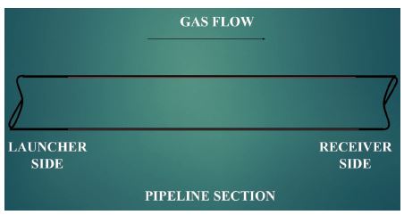
Figure 2. Direction of the Pig Launching Side and Receiving Side
In Figure 2, we see that pig launchers are used at the start of the pipeline, while pig receivers are located at the end of the pipeline. It moves in the direction of gas flow (Fisher, 1998).
The pigging methodology consists of the following procedures: operational procedure, on-site operation, pig launching, pig receiving, pig tracking, safety during pigging, contingency plan (pig struck), and disposal of debris.
The pigging schedule will be distributed to all maintenance bases (Maximum continuous rating (MCR), Next Generation Media Corporation (NGMC), etc.). Downstream consumers must be informed about the availability of alternative fuel in the event of an emergency, as well as fluctuations in pressure parameters caused by pigging operations by the respective maintenance base in charge (Hopkins, 1997). Arrangements for spare filters have to be made by the respective maintenance base in charge to handle additional debris in filters due to pigging activities (Sousa et al., 2021).
All station valves, quick opening closures, and signals shall be tested for proper functioning, and all mainline valves at SV stations are to be ensured that they are in a fully open position and kept in manual mode. Standard Operating Procedure (SOP) should be available at the launcher, receiver, and control room. The pig's velocity and travel time are calculated by using the velocity formula and the pressure and flow parameters of that pipeline section. It is ensured that a transmitter has been installed in every pig except the foam pig to track the pig with an electronic pig tracking device.
Step 1: Separate the trap isolation valve and the kicker line valve.
Step 2: Vent the gas and open the end closure.
Step 3: Insert the pig and close the end closure.
Step 4: Equalize the pressure across the pig.
Step 5: Open the kicker line and trap the isolation valve.
Step 6: Close the main line valve.
The pig will be launched, and after that, we have to again repeat the first step.
The trap isolation and kicker line valves are opened. When the pig approaches the pig trap, the main valve is closed so that the flow is maintained through the kicker line and the pig is received in the barrel. The trap isolation valve and kicker line valve are closed and gas is vented. The end closure is opened and pig removed.
Important points to be noted while performing this task during launching or receiving is enough differential pressure is required if flow and pressure are low, So Dynamic Positioning (DP) has to be created by completely stopping the flow downstream and then quickly opening the Kicker line valve. However, more DP should not be generated when receiving or launching the PIG at the customer end, or at the compressor or pumping station; otherwise, the plant may trip due to low pressure.
Pig tracking shall be carried out at Safety Valve (SV) locations and assessable intermediate points between valves. The location of the tracking points shall be mutually agreed upon at the site. The bi-directional pigs will have a transmitter mounted on their bodies. A handheld receiver with an antenna shall be kept at the locating point. An acoustic pig tracker is also available at the tracking point. The pig makes a distinct sound while passing each weld. This sound is detected by the acoustic pig tracker. Sometimes at some locations, the pig might not be tracked while the pig is moving due to external factors like magnetic interference, electrical noise, EMI, geographical conditions, weather, depth of the pipeline, etc. Each tracking team shall communicate the time of pig passage to the designated person. Two tracking teams with equipment and two vehicles will be available for tracking in every pipeline section under the supervision of one team leader.
During the operation of the barrel end closure, we should not stand in front of the barrel door closure or on the hinged side. Also, it is ensured nobody stands in the line extending from the closure, regardless of the distance. The pig can try to enter the receiver's kicker line. If this occurs, it can cause very high back pressure in the line. In such a situation, the Flow Tee actuator valve is opened rapidly to avoid a pressure drop in the downstream section. To ensure worker safety, all pigging personnel should wear Personal Protective Equipment (PPE).
Another pig should not be inserted in the launcher barrel until the first pig is received and without knowing the condition of the pig or gauge plate. After venting the barrel, while launching or receiving activities, nitrogen purging should be done while opening the end closure. When more dry dust powder with sulphur content is received along with the PIG, it is better to spray. Dynamic Cone Penetrometer (DCP) is inserted into the barrel after opening the end closure to avoid contact with the atmosphere. Otherwise, it may ignite and catch fire.
When the driving force is lost due to pump or compressor failure, the pig stops due to excessive wear of the sealing disc and the consequent loss of drive. The pig's mechanical breakup was caused by a component failure or blockage of the line with excessive dust or debris. Some dent or defect in the line is obstructing the pig.
It is done by pig tracking; an increase in pig upstream pressure and a fall in pig downstream pressure; and delayed receipt of the pig.
Attempts to move the pig forward were made by closing the upstream valve and administering a shock while locating the pig. Both the upstream and downstream valves are closed and the Quick Opening End Closure (QOEC) of the upstream valve is opened for gas venting to try to reverse the pig's movement. If attempts to restart the pig are unsuccessful, then a hot tapping and stopping operation will be required to cut the pipe to retrieve the pig.
The foam pig before and after launching is shown in Figure 3.
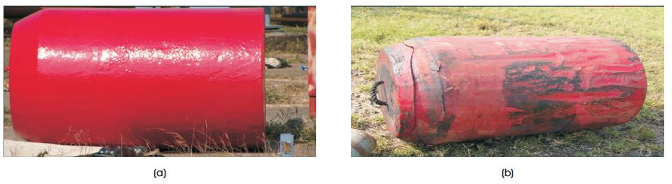
Figure 3. Foam Pig Before and After Launching
The damage caused to the foam pig is shown in Figure 4. As we can see from the above condition of the foam pig after receiving it, there is hardly any damage to it. Hence, the pipeline is suitable for pigging.
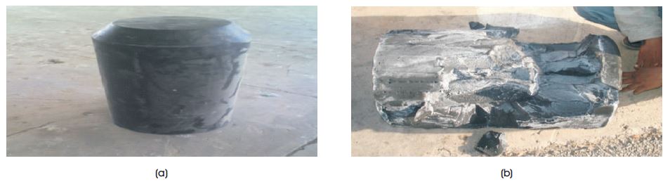
Figure 4. Damage Caused to the Foam Pig
Figure 5 shows the condition of the gauge pig before launching and after receiving.
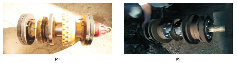
Figure 5. Condition of the Gauge Pig Before Launching and After
As we can see from the above condition of the gauge pig after receiving it, there is a major dent on the gauge plate. Hence, the pipeline is not suitable for pigging. From the side image of the gauge pig after receiving, it is observed that there is no major dent on the gauge plate. Hence, the pipeline is suitable for further cleaning, pigging, and intelligent pigging.
The before and after effects of the cleaning pig are shown in Figure 6.
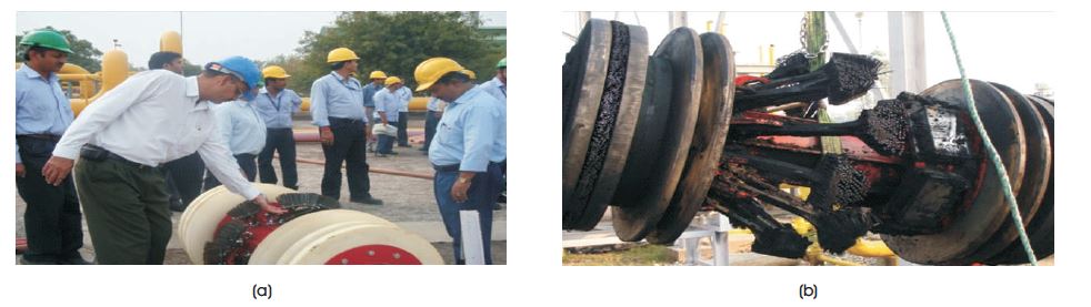
Figure 6. Before and After Effects of the Magnet Pig
We can see from the condition of "Brush + Magnet PIG after receiving the sealing disc. Magnetic discs and guide discs are OK. Hence, the same PIG can be rerun in the pipeline.
The applications of pipeline pigging that are common are as follows.
Removal of biofilms, bacteria, mud, scale, sediment, calcium carbonate, manganese iron, and other pollutants.
Debris removal, including calcium carbonate, manganese iron, particles, scale, and rust.
Removal of contaminants such as scale, rust, bacterial formations, sand, and wax.
Removal of water, rust, scale, and construction debris
Removal of iron sulphides, carbonates, and oxides of iron (known as Black Dust).
Pipelines are often regarded as the most effective way to move gases and liquids over varied distances (Wu et al., 2021). All parties involved have made significant financial, environmental, and operational commitments, and to safeguard these priceless investments, continuing maintenance must be carried out regularly to guarantee the pipeline continues to work at its best. After construction is complete, new pipelines must undergo hydrostatic testing to demonstrate that they will be able to fulfil the approved MAOP (Maximum Allowable Operating Pressure). Pipeline pigs are used to fill pipelines with water during the testing phase and to dewater the pipeline following the successful conclusion of the hydrostatic test.
Pigs are also used to remove any construction debris that accumulated during pipeline installation. In some circumstances, such as with high-pressure gas transmission mains, pigs will also be used to further clean and dry the pipeline to remove any remaining moisture, rust, scale, and debris and to achieve the minimum dew point required by the relevant pipeline building criteria (Nagaraj, 2013).
The following parameters comprise the advantages and disadvantages. Pipeline rehabilitation and clearing, testing for Future Pipeline Projects, tracking and inefficient pumping, high costs of power, pressure lowering, turbidity and discoloration, product reaction, cleaning up trash, product restoration, product separation, and batching, measurements of internal bores, cleaning for the preinspection survey, removing tough deposits, using chemical inhibitors or interior coatings, removing interior forms like rust scale, commissioning, testing hydrostatics, dewatering, and filling.
As pipeline infrastructure ages, corrosion and Self- Compacting Concrete (SCC) will continue to be problems since they reduce pipeline integrity globally. The need to incorporate grossly overstated conservatism during assessments and/or the need to verify crack depths by grinding out crack indications has decreased as a result of the use of Non-Destructive Testing (NDT) techniques to accurately size defects. Sizing data for engineering evaluations will be correct if the kind of problem under inquiry is recognised and the proper calibration and inspection are carried out.
Maintenance personnel have been using highly "smart" pipeline inspection gauges, or PIGs, since the 1960s to discover rust, weak seams, thin walls, and other signs that a pipe requires replacement or repair. Pigs create a screaming noise as they move through narrow spaces. They travel where humans cannot, but controlling them can be difficult because most rely entirely on the pressure fluid inside the pipe for movement. A pig is extremely challenging to halt in one place.
A third of the 1.3 million miles of natural gas pipeline in the United States is also "unpiggable." Some pipes widen before becoming narrower, while others include bends that are too severe for existing PIG technology to negotiate. It becomes more necessary to examine these pipes as they get older and corrode. Some gas transmission lines in the United States date back to the Great Depression, and about 60% of them were installed before 1970. Old cast-iron and steel pipes are gradually being replaced by non-corroding plastic pipes by utilities. Even so, pigging an existing pipe is still much more economical than having a new one installed.
Hagen Schempf, a roboticist at Carnegie Mellon University, and his colleagues created a more advanced inspection tool. The Explorer-II, a 66-pound, eight-footlong wireless robot was recently unveiled by Schempf's team after 10 years of study and around $1 million in support from National Aeronautics and Space Administration (NASA) and the U.S. Department of Energy. Its segmented body easily negotiates bends and turns. Instead of being propelled by the flow of natural gas like other PIGs are, its powerful drivetrain allows operators to precisely regulate where it starts and stops. Additionally, its specially created sensors find minute irregularities in pipe walls before they become problematic.
Traditional PIGs employ permanent magnets to look for variations in the magnetization of the pipe walls that could be signs of corrosion, but the magnetic field interferes with the PIG's motion and slows it down. Permanent magnets are replaced by a small electromagnetic coil in the Explorer II, which detects the same issues without slowing down.
The robot is currently undergoing commercial trials with a Canadian gas company after recently proving its toughness in Pennsylvania by snaking through 2,000 feet of previously impassable pipeline.
Creating appropriate pigging schedules is critical to preserving pipeline efficiency while lowering both capital and operating expenses connected with pipeline systems. To that purpose, operators must precisely assess the needs of each pipeline. The key problem is selecting the correct pig and devising an efficient pigging program. Maintaining pipeline efficiency and cost effectiveness requires rigorous record-keeping and data analysis. Furthermore, pigging operators should stay upto- date on the latest methods and technology that might help them improve their operations.