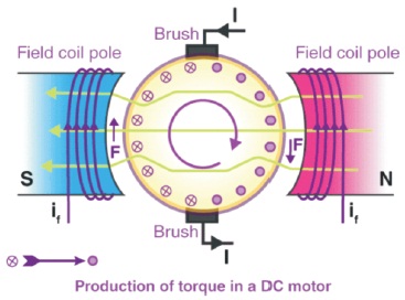
Figure 1. DC Motor
In the recent development of automobile industries, there has been a focus on reducing the environmental impacts of flue gases emitted from Internal Combustion Engines, such as CO, CO2, NOx, and other pollutants, and thus it is critical to develop pollution-free e-vehicles to protect the environment. The goal of this study is to produce a light-weight regenerative electrical bicycle. In this study, a regenerative DC hub motor in the front wheel is employed to generate power from the rotational motion of the front wheel, which is then stored in a power storing device such as a battery or a regenerative convector unit. The stored energy in the storage unit is transferred to a DC hub motor mounted on the bicycle's rear wheel, and the rational moment of the DC hub motor shaft is transferred to the rear wheel motion, which acts as the rear wheel axle. The fundamental advantage of a regenerative e-bike is that it can work in any circumstance without requiring any additional power. When compared to the country's commercially available e-bikes, the regenerative electrical bicycle enhances efficiency.
All vehicles on the road pollute the environment, and the cost of gasoline is rising every day. A remarkable treatment is required to adjust for the shifting gasoline price while also reducing pollution. That would be an unrestricted power transmission system. This task's equipment combines a DC Regenerative motor and a bicycle, allowing for environmentally beneficial energy technology. This takes into account both personal health and environmental concerns ( Vignesh et al., 2015). The bicycle is operated without the use of pedals, with the help of an electrical DC Regenerative motor in the front wheel (Alternator) and a DC electric motor in the rear wheel. Various motivational factors contribute to the successful implementation of the hybrid-electric driven era in the automobile industry.
In recent years, hybrid electric powered motors (HEV) have occupied a significant portion of the automobile market. Since the introduction of the first mass-produced hybrid vehicle in 1997 (the Toyota Prius), their presence on the road has rapidly increased. Internationally, more than five million automobiles have been purchased, and their range is rapidly expanding. All of the major automobile manufacturers have hybrid-electric models on the market, which are either in production or about to be released. A hybrid automobile, by definition, is a vehicle with incredible reassets of ability power that can be converted one after the other into useful kinetic power.
Super-capacitors (electric), batteries (electro-chemical), pressurised fluids (mechanical), revolving flywheel (mechanical), and gasoline (chemical) are some of the ways this ability power might be conserved ( Sankar et al., 2013). HEVs (hybrid electric powered vehicles) are a technological advancement that bridges the gap between traditional automobiles and electric driven motors. They combine an electric pressure device, such as a battery or other power storage tool, with a quick recharge in a renewable portfolio standards (RPS). RPS can be a gasoline or diesel internal combustion engine, a gasoline mobile unit, or a gasoline turbine. HEVs, often known as RPS, are utilised in the present industry and are proven. This RPS recharges the electric garage tool (battery or super capacitor) and can immediately pressurise the wheels with the electric motor. This can be accomplished in two ways: directly through an instantaneous mechanical pressure transfer or indirectly through the provision of electric generated energy to the motor ( Vijayan et al., 2019).
The concept of a motorised bicycle, much alone an electric propelled bicycle, is not new and has existed for over a century. Sylvester Howard Roper of Boston, MA, invented the first non-motor bike in 1867. The Roper steam velocipede, which was essentially a bike driven by a steam engine, has been the result of his creative approach to the bicycle. The electric bicycle did not make its mark on history until 1895, despite the fact that it had been in use for some time at the period. The Ogden Bolten design incorporates a six-pole brush and a commuter DC hub motor that is attached to the rear wheel. He was then granted a US patent. Hosea W. Libbey built an electric bike a few years later that has been propelled by two electric motors. This motor has been built in such a way that it has been connected to the crank set axle. Torque sensors and power controllers were created later in the 1990s, as well as certain modified versions of bikes using NiMH, NiCd, and/or Li-ion batteries, which offered lighter, higher-density batteries. As the year progressed, more and more electric motorcycles with various driving methods were manufactured. Some featured a belt or chain connecting the motor to the wheel. Albert Parcelle of Boston, Massachusetts has been the inventor. By 1992, there were still very few commercial electric bicycles on the market.
The bicycle is created to run using dynamo by Vignesh et al. (2015) in their work. Two or more photovoltaic cells may be used to harness solar energy to provide power to charge the battery, according to Barve (2016).
Today, we intend to keep working on the electric bike concept and find new ways to make a more efficient and practical electric bike. In this paper, we create an electric bicycle that requires no external power and runs on a variety of energy sources such as solar, dynamo, and energy recovered during braking.
Sprockets are used in bicycles, motorcycles, automobiles, tracked vehicles, and other equipment to convey rotary motion between shafts where gears fail or to impart linear motion to a track, tape, or other device. Perhaps the most common sprocket design may be found inside the bicycle, where the pedal shaft is made up of a large sprocket-wheel that drives a chain, which in turn drives a little sprocket at the rear wheel's axle. Early automobiles were also driven in significant part with the help of a sprocket and chain mechanism, which has been mostly modelled after bicycles ( Aikenhead, 2011).
A DC generator (or) DC Regenerative Motor is an electrical system whose essential characteristics are to transform mechanical electricity into electricity. When a conductor receives magnetic flux, an emf is generated, which is based entirely on Faraday's Laws' electromagnetic induction principle. The Faraday disc, the world's first electromagnetic generator, has been designed in 1831 by British scientist Michael Faraday. Generators provide almost all of the power for electric-powered power grids ( Matey et al., 2017). We know that when a progressive conductor is placed in a different magnetic field, an emf is induced inside the conductor, according to Faraday's law of electromagnetic induction.
The direction of the required current changes every time the direction of movement of the conductor changes, according to Fleming's right-hand rule. Consider an armature that rotates clockwise and a conductor on the left that transfers upwards. When the armature has completed 1/2 of a rotation, the conductor's movement can be reversed downward. As a result, the contemporary course in each armature may alternate. However, with a split up ring commutator, the armature conductor connections are reversed, resulting in a contemporary reversal. As a result, we get unidirectional contemporary terminals ( Bhavani et al., 2015; Pucher et al., 1999).
While the DC motor's spherical coil is powered as shown in Figure 1, a magnetic region forms within the air hole. The magnetic area formed is on the other side of the armature's radii. The magnetic area enters the armature through the North pole of the sphere coil and escapes through the South pole of the sphere coil. The conductors on the opposite pole are subjected to the same depth of pressure, but on the opposite side of the path. The torque created by these opposing forces causes the motor armature to revolve.
Figure 1. DC Motor
Even though certain lithium number one mobileular sizes do have lithium-ion rechargeable equivalents, lithium-ion rechargeable batteries are no longer interchangeable with number one types using different chemistry ( Vignesh et al., 2015). The chemistry used in most rechargeable cylindrical cells has a nominal voltage of around 3.7 volts, although LiFePO cells yield the best 3.2 volts. Complete charge voltage (100% charged) is 4.2 volts, and absolutely discharged voltage (0% charge remaining) is 3.0 volts for batteries with a nominal voltage of 3.7 volts.
Lithium-ion batteries come in a variety of sizes as shown in Figure 2 and are frequently integrated into packs for portable equipment. Many types have an internal safety circuit to prevent over-discharge and short-circuit damage ( Desai et al., 2016). This can increase their physical length; for example, an 18650 is approximately 65 mm (2.56 in) long without an inner safety circuit, but may be around 68 mm (2.68 in) long with one. Recharging the cells in a safe and cost-effective manner necessitates the use of a charger designed specifically for those cells. PC battery packs, digital cigarettes, flashlights, electric powered vehicles, and cordless energy equipment are all popular packages.
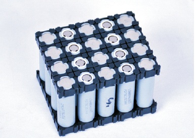
Figure 2. Lithium-ion Battery
Large rechargeable cells are usually given five-digit numbers, with the first two digits representing the (approximate) diameter in millimetres and the next three digits representing the (approximate) top in tenths of millimetres. Not all manufacturers use this Li-ion battery mobile branding device for all batteries. In this battery, each mobileular has a 3.7 volt and a pair of ampere requirements, and the battery that meets the usage of 104 batteries is utilised in a row with 13 cells and 8 columns, with parallel connections. Then, after combining cells with a rated voltage of 48 volts and a 20 ampere battery backup as in Figure 3, the e-bike is ready to ride.
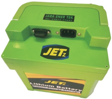
Figure 3. 48 V and 20 A Lithium-ion Battery
The most charging time for a regenerative electric convector is 3.5 hours. Specifications for Batteries rated 20 Ah, Nominal Voltage: 48.1 V, Voltage Range: 39 ~ 54.6 V, Dimensions (L x W x H): 230 x 100 x 140 mm, Maximum Continuous Charging Current: 40 A, Maximum Continuous Discharge Current is 80 A for 3 second, Maximum Permanent Discharging Current: 40 A, Operating Temperature: Charge: 0 °C – 50 °C; Discharge: 20 °C – 60 °C, Providing 1500-1800 cycles, which is four times longer than a lead-acid battery's 200-500 cycles. Highest-Level Safety is only 1/4 the load of a lead-acid battery with same potential ( Barve, 2016).
The above-mentioned components were constructed for the e-bike in this study. For the convenience of converting a standard bicycle, 26-inch wheel rim is mounted in the rear wheel in the bicycle frame. 36 holes spokes with 960 W and 48 V hub motor rear wheel were utilised in this work. Throttle and Horne controls are mounted in the bicycle handlebar on the right and left sides, respectively, as on a motorcycle. With the use of a regenerative DC electrical motor, 960 W and 48 V DC regenerative convertors were employed to transform mechanical energy (rotary motion) into electrical energy in this study (Front wheel).
A front-wheel regenerative hub motor is mounted on the bicycle frame's front side (24-inch wheel rim with 36 holes spokes) as shown in Figure 4. The power collected from the front-wheel is used to power the Regenerative DC convertor, which is fixed with one step-up module and an adjustable booster power supply module for step-up and for constant power supply to the DC convector. A two-way locking mechanism has been used here for the safety of the e-vehicle, one of which has a battery-operated key system installed on the front side of the bicycle handlebar. That will indicate the battery percentage like 100%, 80%, 60%, and 30% etc.
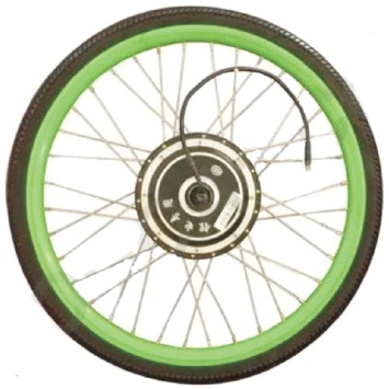
Figure 4. Regenerative DC Hub Motor Front Wheel
Figure 5 depicts the key control, which includes both manual keys for LED headlamp control and a remote control for centre locking. If we use the centre lock with the remote to drive the bicycle forward, it will automatically create an opposite direction moment to stop the forward rotational motion. In addition, the front wheel axle lock in this e-vehicle uses a manual locking mechanism in comparison to the U-type locking clamping system. These battery backup and control devices are housed in a sheet metal box beneath the bicycle's cushioning layer ( Barve, 2016). This cushioning layer has been carefully developed by TVS excel vehicle seat for comfort when driving an e-bike over long distances. This e-bike has a three-speed control switch next to the throttle control, allowing three separate speed ranges of 20 kmph, 30 kmph, and 40 kmph, respectively. For the smooth and good couching effect of the driving person, this research work is done on a dual suspension attached bicycle.
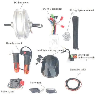
Figure 5. DC Hub Motor and Components
The DC Regenerative hub motor's (Dynamo/Alternator/ Generator) function is to convert mechanical energy to electrical energy. Initially, it will give motion to the front wheel with the help of manual pedalling. This human effort is converted into rotary motion of the front wheel, and developed power is stored in the battery through regenerative convertor (350 W and 48 V) to develop power during the rotational motion of the front wheel. The bicycle front wheel hub motor, which works as a dynamo, is equipped with a DC Regenerative hub motor ( Aikenhead, 2011).
It is propelled by the bicycle's rear wheel, which is powered by a battery. The DC Regenerative hub motor is activated as the wheel revolves. The front wheel's DC regenerative hub motor is connected to the controller, which is connected to the battery. Initially, power is delivered to the front wheel with the help of guiding paddling, and then the battery is charged mechanically often with the help of a DC Regenerative hub motor. Terminals are built into the battery. One is a good terminal, whereas the other is a bad terminal ( Aikenhead, 2011).
The string connections were built to allow electrons to flow from one junction to another. When the motor is powered by current, the stator subject coil is magnetised, causing the rotor shaft to rotate in a counter clockwise direction. Another hub motor is installed in the bicycle's back wheel and serves as a motor to deliver rotary action to the front wheel. The power of the DC regenerative hub motor is transferred to the wheel over time, allowing the bicycle to move in the forward direction. The above-mentioned steps are carried out at all times when the bicycle is in motion.
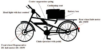
Figure 6. Design of Regenerative E-Bicycle
Figure 6 shows the design of planned e-bicycle. Figure 7 explains the circuit diagram of the concept used. Figure 8 shows the actual e-bicycle developed. A bicycle, sometimes referred to as a bike, is a human-powered, pedal-driven, single-tune vehicle with wheels attached to a frame, one behind the other. This bicycle has been built expressly for the job, with each operation jogging at the same time (with assist of a step-up module with adjustable booster strength deliver module to charge the battery in addition to battery power to rear wheel hub motor). The regenerative motor generates 48 V and 7.29 A continuously through guide pedalling at a minimum speed of 15 kmph to charge the battery on a regular basis. Because voltage fluctuates from time to time, and one installation booster has been attached between the regenerative motor and the regeneration controller to change the constant 48 V has been used to charge the battery.
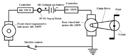
Figure 7. Circuit Diagram
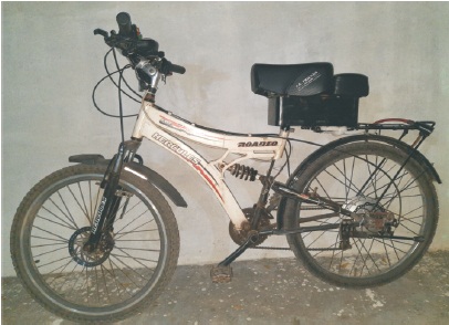
Figure 8. Regenerative Electrical Bicycle
In this study, three separate test-drive results were displayed as shown in Figures 9, 10, 11, 12 and 13. This test can be performed by three different weighted individuals: 100 kg, 80 kg, and 60 kg.
The findings of e-bicycle distance travelled by three distinct weight groups are shown in Figure 9. The first individual to be tested weighed 100 kg and the results were shown in blue colour. The e-bicycle reached a distance of 60 km when driven at a speed of 20 kmph in economic mode, 55 kmph in normal mode, and 48 kmph in sports mode. This test drive took about 15 days. Person weighing 80 kg has been the second to be tested. The result of the e-bicycle speed range of 20 kmph in economic mode achieved the distance of 68 km, in the regular mode at the speed range of 30 kmph, the e-bicycle reached the distance of 60 Kms, and finally at the sports mode speed range of 40 kmph, the e-bicycle reached the distance of 55 kms. The final test subject weighed 60 kg, the result is shown in green colour on Figure 9. The remaining of the Figure 9 is in economic mode. At the regular mode, speed of 30 kmph is required to reach the e-bicycles's distance of 67 km, and at the sports mode, speed of 40 kmph is required to reach the e-bicycle distance of 62 km.
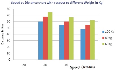
Figure 9. Speed vs. Distance Chart with Different Weighting Conditions
The battery discharge characteristics of the e-bicycle running condition at economic mode for the speed range of 20 kmph with 100 kg weight person are shown in Figure 10. The lithium-ion battery has discharging power at a rate of 100% to 80% when the distance reached 32 km, then 80% to 60% when the distance reached 16 km, 60% to 30% when the distance reached 8 km, and finally 30% to 0% when the distance travelled 4 km. In these conditions 60 km have been reached for full charging condition under above-mentioned weight and speed range.
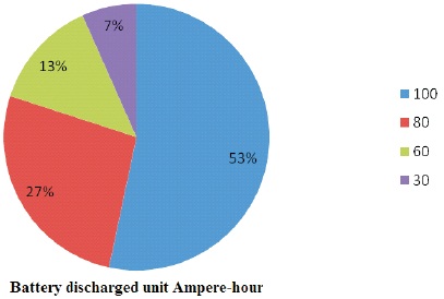
Figure 10. Battery Discharge of 20 kmph Speed at 100 kg Weight Condition
The battery discharge characteristics of the e-bicycle running condition at economic mode for the speed range of 30 kmph with 100 kg weight person are shown in Figure 11. The lithium-ion battery has discharging power at a rate of 100% to 80% when the distance reached 30 km, then 80% to 60% when the distance reached 14 km, 60% to 30% when the distance reached 7 km, and finally 30% to 0% when the distance travelled 4 km. In these conditions 55 km have been reached for full charging condition under above-mentioned weight and speed range.
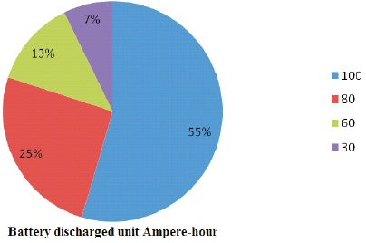
Figure 11. Battery Discharge of 30 kmph Speed at 100 kg Weight Condition
The battery discharge characteristics of the e-bicycle running condition at economic mode for the speed range of 40 kmph with 100 kg weight person are shown in Figure 12. The lithium-ion battery has discharging power at a rate of 100% to 80% when the distance reached 26 km, then 80% to 60% when the distance reached 12 km, 60% to 30% when the distance reached 6 km, and finally 30% to 0% when the distance travelled 4 km. In these conditions 48 km have been reached for full charging condition under above-mentioned weight and speed range.
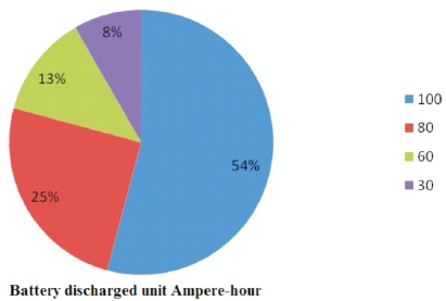
Figure 12. Battery Discharge of 40 kmph Speed at 100 kg Weight Condition
Finally, Figure 13 shows the results of battery charging categories, which show the different percentages of charging for different distance travelled conditions. For example, in the first 15 km, the battery charges to 30%, in the next 21 km, the battery charges to 60%, and after 36 km, the battery charges to 80%, and the full 100% battery can regenerate the motor to run continuously for 3 hours and 30 minutes.
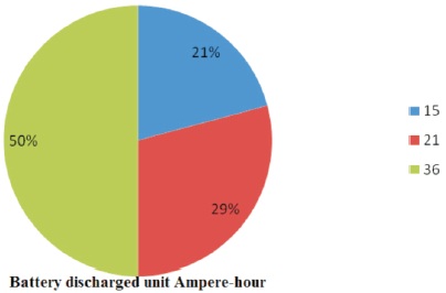
Figure 13. Battery Charging 30% for 15 km, 60% for 21 km, and 80% for 36 km
The specifications for the DC motor used for design are listed in Table 1.
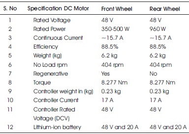
Table 1. Specifications
As per Ohms law
Power = Voltage x Ampere
Power= 48 * 20=960 Watt
Watt / Voltage = Ampere
960/48 = 20 Ampere
P = 2πNT/60
P - Power in W, N - Speed in rpm, T - Torque in Nm
D - Diameter of the motor - 0.180 m
960 = 2π 404 T/60
T = 22.7029 Nm
T = 22702.9 Nmm
T = πτD3/16
τ = 2043.261 x 16/π *(0.180)3
τ= 363.2464/0.9048
τ = 32692.176/0.01832
τ = 1784507.4235 N/m2
τ = 1.7845 N/mm2
The eco-friendly regenerative electrical bicycle has been successfully manufactured in this research project. In comparison to other weight and speed ranges, a maximum of 75 km has been attained for a 60 kg mass at a speed of 20 kmph. While the e-bike reached a distance of 75 km, the battery gained 80% of its energy. The energy is obtained by running the e-bike for three and a half hours with a current output range of 7.29 A.