Figure 1. Design Methodology of Bell Nozzle
The engine's interpretative thrust production, such as nozzles, has been restructured for higher staging. Modern expansions of combustion systems, such as rocket nozzles, will be adjusted to meet the needs of today's applications. The bell and dual bell nozzles are an example of such advancements. From the four fundamental types of bell nozzles, one such bell nozzle is chosen. The parabolic shape optimised the thrust of an axisymmetric nozzle. The basic goal of constructing a bell nozzle is to produce as little shock waves as possible. A dual bell is explored and studied in this work using CFD flow. The main focus is on the design and analysis of dual bells based on altitudes ranging from 2, 5, 7, 10, 12, 15, inlet mass flow rate of 5 kg/s, inlet temperature of 1200 K, and NRP value of 12. We had performed simulation to the design and flow simulation with the help of SolidWorks 2020 by adjusting the value of inlet pressure of the fluid and calculating with the help of ambient pressure with regard to altitude. Flow simulation is done in a three-dimensional model.
A nozzle is a structure that allows hot gases to flow in order to generate high thrust. Fluid is released at a high velocity and low pressure, at high temperature via a nozzle. The slope of the counter is modelled on the parabolic equation, and the dual bell nozzle has been created based on the requirements of the mission of the rocket employed. The throat's breadth is determined by the throat flow, which determines the mass of fuel that will be extended into the contour (it is divided as two parts first contour and second contour). The gases will travel from the nozzle's inlet to the throat, where they will pass through the first and second contours before being released into the atmosphere.
In a thermal chamber, a nozzle is utilised to convert chemical energy to kinetic energy. The dual bell nozzle produces isentropic flow. A plane of discontinuity is used for transition from supersonic to subsonic flow. The shock wave is the plane of discontinuity, and the flow-through shock is no longer isentropic. It comprises of a high angle (20 to 50 degrees) at the connection between the nozzle and the counter, followed by a contour slope at the exit with an angle of less than 10 degrees.
The contour structure is used to provide the fluid a larger angle of expansion just after it passes through the throat. At the nozzle exit, the nozzle is designed to produce a virtually straight flow of fluid. The larger the expansion at the throat, the more expansion shock waves is produced. If the slope reversal influences the exit to near zero degrees, compression shock waves are produced. A well-designed nozzle generates a pair of shock waves that are imposed on each other and cancel each other out.
The nozzle's primary goal is to increase the kinetic energy, energy loss, and pressure of the flowing material. The fluid attains sonic velocity when the nozzle's pressure ratio is too high. The thrust is generated in large part by the nozzle design. The amount of thrust generated is determined by the mass-flow rate, exhaust gas speed, and nozzle pressure. It lacks the engine motor's pliability due to the lack of throttling capability. A pintle nozzle is used to compensate for this. The pintle's potential lies in the ability to regulate pressure by varying the throat area of the nozzle.
Chada et al. (2020) made a study on conceptual design and shape optimization of pintle and concluded that the pintle's performance may be improved by varying the shape of the pintle. Genin et al. (2012) had studied numerical investigation of dual bell nozzle flow field and concluded that the recirculation area in the separated extension during sea-level mode shows the most difficulties. Schneider et al. (2013) determined that the impact of a film-cooled dual-bell nozzle extension shows transition behaviour in operation. The dual bell nozzle has higher overall performance than the single bell-shaped nozzle, according to Sreenath and Mubarak's (2016). The numerical design of a dual-bell nozzle by Ferlauto and Marsilio (2003) concluded that the extension to three dimensional flows is simple, but it comes at the cost of a flow field evaluation that is unsteady. Due to an expansion at the nozzle exit for an over-expanded nozzle flow, the pressure drops much below the value of the free stream pressure in the case of a supersonic outer flow (Barklage et al., 2017). The transition between sea-level and altitude mode occurs at lower NPR values than with a subsonic outer flow. Akib et al. (2017) investigated the characteristics of a dual bell nozzle using a computational fluid dynamics characterised developed model of a dual-bell nozzle profile, as well as the behaviour and fluid parameters that it had best-optimized.
The influence of Reynolds number on the hysteresis behaviour of a dual-bell nozzle has been studied by Barklage et al. (2019), who found that numerical results for the high Reynolds number case agreed well with experimental data. In comparison to the experiment, numerical simulations predict a higher NPR-value for transition and retransition in the low Reynolds number case. The transition duration has been measured with two methods: pressure measurements and schlieren optics, and has been found to be in the order of a few milliseconds in experimental study of dual bell nozzles (Nürnbergergénin & Stark, 2007).
The pressure gradient has an effect on transition length and local front velocity in both techniques. Beena et al. (2017) investigated the CFD of a bell nozzle and found that it decreased as the NPR increased. At Mach stem in viscous prediction, the normal shock strength generally increases. The influence of wake flow is critical in flow behaviour of dual-bell nozzle (Génin et al., 2020). Davis et al. (2015) used experimental and computational methods to determine the best design for a dual bell nozzle that produces an optimised output.
A model of the dual bell nozzle with the help of the SolidWorks software has been created after conducting a thorough investigation of the dual bell nozzle. A fine messing operation and a detailed procedure has been produced with the help of flow simulation SolidWorks 2020 workbench.
In the dual bell nozzle, air is considered the working medium. The value of the operating parameters is derived from the inlet. Here, we must choose the proper approximation for the excess command under supervision and check plot to see how the iteration is progressing. Once every parameter is set out, the simulation is pulled off till the value gets converged to indispensable. A mathematical model is designed for differential equations that govern the variation of the physical system, and the described frontier conditions.
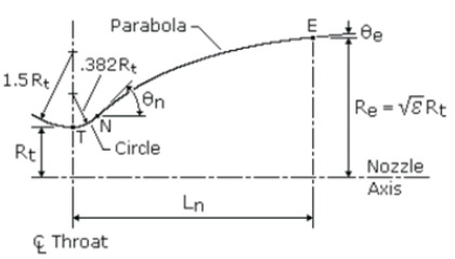
A dual bell nozzle is constructed (Figure 1) using a convergent part and the divergent part from four curves.
Figure 1. Design Methodology of Bell Nozzle
An initial, large circle coming from the inlet to the throat, a smaller circle exiting the throat, and a parabola to extend the approximated bell contour to the start of second bell or counter to extend the approximated contour to existing plane is designed in the model. The following equation determines the length of the nozzle.
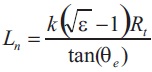
Where k is a constant value based on the present length of the nozzle.
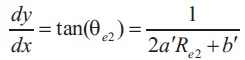
The flow deviate with an angle of θe. The radius of the throat is considered as Rt and ε is considered as the area ratio of the nozzle.
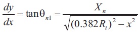
The centre of the throat is described in two curves, where the first curve and the second curve has been defined as the entrance and exit of the throat respectively where the equation of the two curves is defined as,
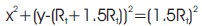
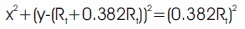
The equations coefficients are described with the help of derivatives at the section where the circle from the throat and the parabola coincide, xN, and the nozzle length. To describe xN, the angle, θN is mandatory to be defined, and the second curve equation must be equal to its tangent.
Then the equation is described as,
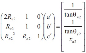
The equation can be described in matrix form as,
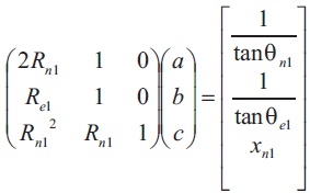
The matrix can then be solved for the coefficients.
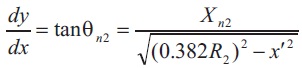
The design of the nozzle is similar to the second curve. So the equations considered are,
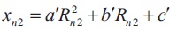
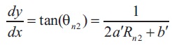
Their matrix form is,
The area ratio is used to build the convergent section, and the angle is kept constant at 45 degrees. The area ratio is calculated as 11.2983, and the throat radius is 0.0305 m.
The throat radius is 0.0305 m when dual-bell nozzle (first contour) is included. The initial contour is 0.3673 m in length.
The angles of nozzle are,
θn1=40.0000
θe1=14.237
The area ratio ε1 = 31.47
For the second contour, the throat radius is 0.0305 m when dual-bell nozzle (second contour) is included. The initial contour has a length of 0.2732 m.
The angles of nozzle are,
θn2=40.0000
θe2=14.237
The area ratio ε2 = 64.5603
The design parameters are indicated as shown in Table 1.
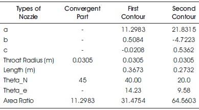
Table 1. Design Parameters
The nozzle inlet pressure parameter has been determined using the following calculations based on ambient pressure.
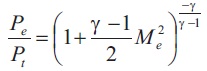
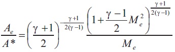
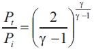
Using these formulas, the values in Table 2 has been found.
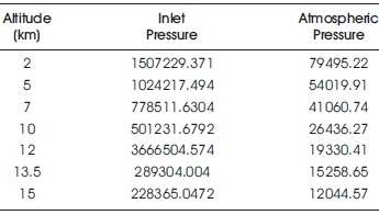
Table 2. Operating Pressure Conditions
Design parameters for the nozzle have been developed and using those parameters, a simple sketch of the nozzle has been drawn as shown in Figure 2. It revolves through an axis and produces a CAD model as shown in Figure 3. The nozzle's CAD drawing are created using the specifications listed in Table 1.
Figure 2. Dimensions of Nozzle
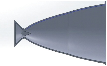
Figure 3. CAD Model of Nozzle
To create an optimization condition, a pintle is placed at the nozzle's throat, and the CFD has been performed by the SolidWorks flow simulation. The operating parameters of the nozzle are to produce high force thrust, so the simulation at a constant inlet flow of 5 kg/s and a constant temperature of 1200 °C has been performed, while varying the pressure based on the altitude of 2, 5, 7, 10, 12, 13.5, 15 km. The flow variation in the dual bell nozzle is observed, and the fine meshing is performed. The flow boundary conditions are established, such as all nozzle walls are treated as real walls, and the fluid or gas is treated as air because it has similar properties, and all of these considerations are required to analyse the flow simulation. Solid Works 2020 is used to simulate the flow nozzle model. To simulate the chosen geometry, Solid Works is governed by the Navier-Stokes equations. Fluid dynamics is the most important branch of engineering study, and Bernoulli's theorem is a well-known concept in fluid dynamics. He explained that if the fluid flow is uniform, it does not face any changes in gravitational potential energy. Then a drop in the fluid's pressure is harmonised with the fluid's velocity rise. He stated that during the transition, the complete mechanical energy of the flowing fluid, including fluid pressure energy, potential energy of gravitational elevation, and fluid kinetic energy, remained unaltered. Bernoulli's theorem is based on the principle of energy conservation. When fluid flows between two horizontal tubes with different cross-sectional areas, the fluid exerts the minimum pressure at the smallest area and vice versa.
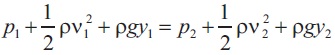
Where ρ is described as the pressure,
ρ is the density of the fluid,
The gravity is denoted as g,
y is the height from the plane.
At a steady flow, incompressible flow, frictionless flow, and flow along a streamline, Bernoulli's equations have a disadvantage. The expanded Bernoulli's equation can be used to investigate typical practical problems.
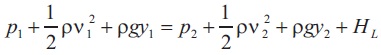
Where, HL is the friction on wall's head loss.
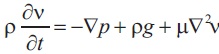
The Navier-Stokes equation is named after Claudelouis Navier and George Gabriel Stokes, two prominent scientists. The principal newton's second law of motion puts this equation into action in the engineering and science streams. The Navier-Stokes equation has a unique and functional purpose. It is possible to observe the relationship between all the pressure, temperature, density, and velocity of a flowing fluid. The Navier-Stokes equations are a combination of Euler's equations that deal with the viscosity of a stream fluid. The Navier-Stokes equation is made up of continuity, three time-dependent equations, and three time-independent equations.
Based on the conditions in Table 2, the inlet parameters are applied at different elevations of 2, 5, 7, 10, 12 and 15 km. The air input mass flow rate is set to 5 kg/s and the temperature is set to 1200 K.
The simulated results are given in Table 3. The results in Table 3 are indicated in the form of graphs as shown in Figure 4, 5, 6, and 7.
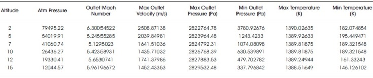
Table 3. Results
Figure 4 depicts the variation of maximum velocity with altitude, while Figure 5 depicts the variation of Mach number with altitude. Figure 6 depicts the variation of maximum pressure with altitude, and Figure 7 depicts the change of minimum pressure with altitude.
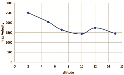
Figure 4. Altitude vs. Max Velocity
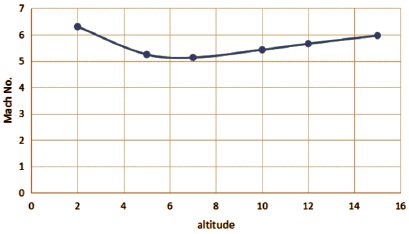
Figure 5. Altitude vs. Mach Number
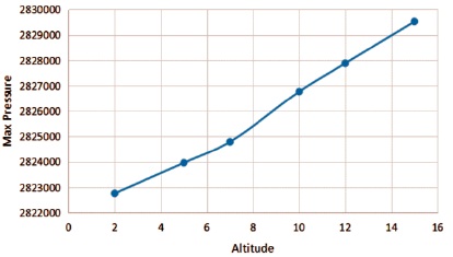
Figure 6. Max Pressure vs. Altitude
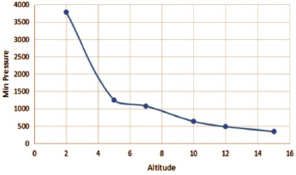
Figure 7. Min Pressure vs. Altitude
The design parameter is created according to the parameters, and the work is done in SolidWorks 2020. SolidWorks Flow Simulation 2020 has been used to study the flow at various altitudes. The results are positive, and the flow has been improved. As the altitude rises, the outlet pressure rises, whereas other metrics display a pattern of decreasing and then increasing parameters except velocity. At various elevations, the nozzle and the outlet have shown good agreement. Due to the shortage of time, various adjustments, testing, and experiments have been postponed (i.e. the experiments with real data are usually very time consuming, requiring even days to finish a single run). Changes in pintle shape, nozzle design, pintle position, and so on will be addressed in future work.