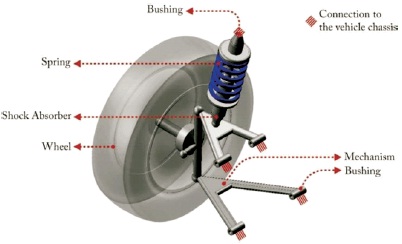
Figure 1. The Main Components of a Suspension System
Suspension system acts as an important mechanical structure in vehicles to achieve ride comfort and stability. This suspension system comprises of a system of springs, dampers and linkages which connects the chassis to its wheels. The performance of the suspension system directly affects the ride comfort and handling safety of the vehicle. Therefore, the suspension system of a vehicle needs to be durable, light weight, efficient and structurally stable. Researchers are optimizing and refining their suspension system designs in search of perfect ride comfort coupled with stable race-worthy handling. In the suspension system, the control arm acts as most important part and it is assumed as the research object now-a-days. This paper covers essential aspects of vehicle suspension systems. This paper begins with the introduction of the role of suspensions in cars and a description of their main components and types of suspension system. Then, a literature review on recent developments in the design and analysis of control arm including their disadvantages and advantages has been provided. Finally, the scope of future work in the design and analysis of control arm is discussed.
The suspension system comprises of a set of springs and shock absorbers which connects the chassis to its wheels. It ensures that the wheels remain in contact with the ground and also minimizes the vehicle rolls. Therefore, it provides a smooth ride over rough roads. It has four main components: mechanism, spring, shock absorber, and bushings which are discussed in detail. The main desired features of a suspension system are: independency, good camber control, good body roll control, good space efficiency, good structural efficiency, good isolation, low weight, long life and low cost. Researchers usually study the design of a suspension system on the following three important principles (Appleyard & Wellstead, 1995; Cao et al., 2008; Williams, 1994).
Ride Comfort isolates the vehicle body from external disturbances coming from irregular road surfaces and internal disturbances created by cornering, acceleration, or deceleration.
Road Holding keeps a firm contact between the road and the tires, in order to have good handling performance.
Stability ensures that the vehicle will be stable in every maneuver and to react to variations in load, which are generated by changes in the number of passengers and luggage, or from internal disturbances.
A suspension system is made of four main components - mechanism, spring, shock absorber, and bushings as shown in Figure 1 (Goodarzi & Khajepour, 2017).
Figure 1. The Main Components of a Suspension System
Researchers have proposed different types of suspension mechanism in the literature. Some of them contain more than one arm that connects the chassis to its wheels. The main function of them is to transfer all forces and moments in different directions between the ground and the chassis. The mechanism of a suspension system determines some of the most important characteristics such as suspension geometry and wheel angles and their relative motions. Over the rough roads, wheel angles experience the variation which causes a change in tyre forces and hence, the ride comfort, road holding and stability are directly affected. The mechanism also determines the weight of a particular suspension system. Researchers have found that the use of heavy materials in its construction decreases the ride comfort, whereas the use of light materials improves the ride comfort but they are more expensive.
The spring is usually a winding wire or a number of strips of metal that have elastic properties. It converts kinematic energy into potential energy or vice versa. It supports the vehicle's weight and makes a suspension tolerable for passengers. Researchers have found that the use of high stiffness springs increases the road holding and handling but it decreases the ride comfort. Hence, there exists a limitation while choosing appropriate spring stiffness.
The shock absorber is a mechanical or hydraulic device to dampen impulses and dissipate kinetic energy. The shock absorber with high damping coefficient increases the road holding and handling but it decreases the ride comfort. Hence, there also exists a limitation while choosing appropriate shock absorber.
The bushing minimizes the vibration and isolates the noise by preventing the direct contact between two metal objects. Bushing uses the soft materials such as rubber for isolation. Different types of vibration isolator are used to connect various moving components to the vehicle body or suspension frame. Different types of bushing are also used which are classified by the number of DOF between the two connected parts that they support. The most common type of bushing is revolute joints. Bushings act as one of the most expensive parts in a suspension system.
A passive suspension is a conventional system which is composed of the non-controlled spring and the shock absorbing damper with constant coefficients, while active suspension system is composed of a controllable actuator, a mechanical spring and a damper. In active suspension, actuator is regulated by a control algorithm using data from sensors attached to the vehicle. Active suspension systems employ a controllable actuator between the sprung and unsprung masses and it is able to both add and dissipate energy to and from the system. In semiactive suspension, the damping coefficient is varied by a variety of methods but still the suspension system can only dissipate the road forces and can't add additional force to the system. Passive suspensions have constant damping coefficient and it only responds to the external excitation passively, and do not allow any active control (Omar et al., 2017).
Active suspension provides a smooth ride in the car and maintains control of the vehicle over rough field or in case of sudden stops. The passive, semi-active and active suspension system is pictured in Figure 2.
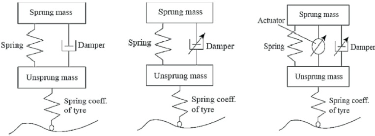
Figure 2. Passive, Semi-Active and Active Suspension Systems (Omar et al., 2017)
In independent suspension system, the movement of a wheel on one side of the axle is independent from the movement of the wheel on the other side of the axle while in dependent suspension system any movement of one wheel is translated to the other wheel. Figure 3 shows a vehicle with its right wheel going over a bump. It can be clearly seen that the wheel can negotiate the bump without disturbing the other wheel in case of independent suspension system while the other wheel tilts in case of dependent suspension system. Hence, independency of wheel movement improves a vehicle's ride comfort, road holding, and handling. Examples of dependent suspension system are Leaf Spring Suspension, Push and Pull Rod and Anti-Roll Bar Suspension. Examples of independent suspension system are Macpherson Suspension, Double Wishbone Suspension and Trailing Arm Suspension.
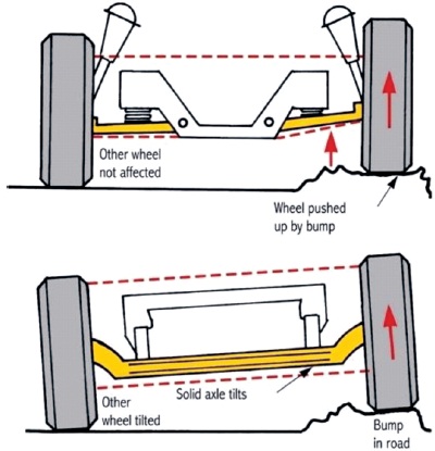
Figure 3. Independent vs. Dependent Suspension Systems
In Kavitha et al. (2019) authors have proposed a method to improve handling characteristics of the vehicle by using double wishbone suspension arms which controls chamber and toe angle in an adaptive manner. In this method, two telescopic arms with actuators change the chamber and toe angle of the wheel dynamically in a closed feedback manner. In this mechanism, PID controller is used which triggers the actuators based on the chamber and toe angle input received from sensors. The physical quarter car modelling has been done in Solid works and analysis has been done in MATLAB. The simulation results show that 89% of chamber reduction and 45% of toe reduction is achieved.
In Mahmoodi-Kaleibar et al. (2013), Genetic Algorithm (GA) is proposed to optimize the geometric parameters of suspension system. The modelling and analysis has been done in ADAMs. The results are evaluated by varying the geometric parameters and by varying the steering angles. It is found that the optimized suspension system improves the handling, stability and ride comfort by reducing the chamber angle variation.
In Saurabh et al. (2016), the authors have designed a front double A-arm push rod suspension system in context to formula student race car. The CAD modelling of the components has been done in Solid works, and ANSYS workbench is used for finite element analysis for the same. The authors have performed both kinetic and dynamic analysis of the proposed model. This paper mainly focuses on design and analysis related aspects of the formula racing cars.
In Singh and Saha (2018), the authors have proposed optimization of the structural strength of the components and performed the stress analysis. The results show that the stress on the components has been decreased and falls well within the yield stresses i.e. 211.06 MPa for the given loading condition. It has been found that the minimum safety factor has been 1.1845 which clearly shows that the component is safe.
In Patil et al. (2013), the comparison of stress and static load conditions deflection in steel lower wishbone arm and composite lower wishbone has been done. It is seen that deflection as well as natural frequency of composite lower wishbone arm is higher as compared to steel lower wishbone arm with the same loading condition. The proposed carbon fiber suspension arms achieve an average weight saving of 27% as compared to the steel arms.
In Patil and Kharade (2016), Finite Element Analysis of existing lower wishbone arm has been carried out. The lower wishbone arm is optimized using topology optimization. The comparative study of the existing and optimized lower wishbone arm has been performed using the ANSYS software. The optimized lower wishbone is also fabricated. Then, the FEA results and experimental outcomes were compared.
In Kulkarni et al. (2014), the force acting on lower wishbone has been studied when the vehicle has been subjected to critical load condition. The CAD modelling of lower wishbone arm has been done using Pro-E software packages while the optimization and analysis of lower wishbone arm has been done using Hyper works. The results show that the obtained values for the maximum stress and maximum displacement are lower than safer limit. It is found that the change in material leads to change in resonance condition. It is also observed that topology optimization generates an optimized material distribution for a set of loads and constraints within a given design space.
In Gunjan and Sarda (2018), the lower wishbone arm is analyzed and optimized using the ANSYS topology optimization tool. The results show that the total deformation, maximum shear stress and mass is reduced as compared to the previous existing lower wishbone arm which in turn reduces the production cost of the lower wishbone arm.
In Prashanthasamy et al. (2016), the existing design is optimized by using aluminum alloy. The CAD modelling has been done in CATIA, FEA analysis has been done using Hypermesh and the static and dynamic analysis has been done by using Abaqus. The results show that the new design with aluminum alloy reduces the stress to 30% as compared to the existing design. The deformation in the new design is almost reduced to 10% as compared to existing design.
In Mahamuni and Shinde (2015), weight optimization of wishbone arm has been carried out by reducing the weight of chassis using topology optimization. The static analysis of the wishbone arm has been done by using Hypermesh and Radioss. The dynamic analysis has been done by using ANSYS. The results show that weight of wishbone arm can be reduced by 13% which in turn saves material cost and reduces fuel consumption.
In Manjhi et al. (2017), various aspects related to design and analysis of suspension system for All Terrain Vehicle (ATV) is discussed. The modelling of the components has been done by using CATIA. The analysis has been done by using NASTRAN/PATRAN commercial FEA software. The Lotus software is used for the simulation of front and rear systems. Then, the system has been fabricated and its performance has been duly tested which has been found to be satisfactory in all the aspects such as safety, comfort, and stability.
In Pachauri et al. (2017), various aspects related to design and analysis of independent suspension system for All Terrain Vehicle (ATV) is discussed. This study mainly focuses on design of all-terrain vehicle, as the ATV have to sustain the effects of large rocks, downed logs, bumps and mud holes etc. The CAD modelling of suspension control arms has been done by using Solidworks. The analysis has been done using ANSYS and the Lotus software is used for the simulation. Then, the performance has been tested and found to be satisfactory in all aspects such as safety, comfort, and stability.
In Taksande and Vanalkar (2015), the stress analysis of lower wishbone arm has been done by using the different materials. The analysis has been done using ANSYS. The results show that the performance of Fe410 material has been much better than of the EN 24 material.
In Deore et al. (2018), design and analysis of double wishbone arm is discussed. The double wishbone suspension arm is designed and analyzed using CATIAV5R20 software. The dimensions of upper and lower arm were calculated. The roll centre of ATV by geometry of double wishbone suspension system has been also calculated. The results show that better performance, reduction in cost and weight of suspension assembly has been achieved.
In Ijagbemi et al. (2016), a study has been carried out on vehicle suspension system (VSS) by using Finite Element Analysis (FEA). In this study, the fatigue life, von misses stress, factor of safety and stability were analyzed. The study also focuses on how the weight and size of the suspension system can be reduced. The comparative study has been performed with different materials. It has been found that Titanium Ti-13V-11Cr-3Al drastically reduces the weight of the car and gives better result in terms of strength and durability which in turn reduces CO2 emission and its negative effect on the climate.
In Soo et al. (2015), the use of lightweight materials and multi-material concepts in car manufacturing has been carried out. The results show that significant reduction in carbon dioxide (CO2) emissions has been achieved. In this paper, the varied ranges of joining techniques were used to join multi-material vehicle.
In Kumar (2020), the premature failure analysis of suspension system is studied. The authors highlighted that the major reasons behind the premature failure of suspension system is insufficient deflection. It is also highlighted that the life of suspension system also depends on deflection capacity under dynamic condition. The bond graph technique is used for modelling and simulation. In this paper, an attempt has been made to study the dynamic behaviour of passenger car through bond graph modelling technique and to evaluate the different parameters through simulation at various speeds.
It is concluded that the design of adequate suspension system is a highly and difficult control problem due to the complicated relationship between its components and parameters. A broad range of design issues and challenges were carried out by the researches in this field. As degrees of freedom goes on increasing from one degree (whole system) to four, seven, eight etc. complexity in analysis increases.
It is also observed that the control arm act as most important part of the suspension system and it keeps the wheels of a motor vehicle from uncontrollably swerving when the road conditions are not smooth. The control arm suspension normally consists of upper and lower arms. The upper and lower control arms have different structures based on the model and purpose of the vehicle. The lower control arm takes most of the impact that the road has on the wheels of the motor vehicle. It either stores that impact or sends it to the coil of the suspension depending on its shape. During the actual working condition, the maximum load is transferred from upper wishbone arm to the lower arm which creates possibility of failure in the arm. Hence, it is essential to focus on the stress strain analysis study of lower wishbone arm to improve and modify the existing design. The material of the lower wishbone can also be optimized to improve the performance of existing design.
It is also concluded that the process of the topology optimization which involves the material distribution can reduce the weight of the existing industrial component. Therefore, the weight of the control arm can be reduced further using the different materials.