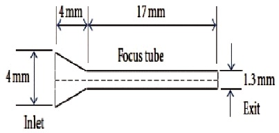
Figure 1. Dimension of a Single-step Nozzle (Deepak et al., 2012)
Abrasive water suspension jet (AWSJ) machining process mostly cut stronger materials and some steel tools in industries. This process encourages material removal without the involvement of heat. Nozzle wears resulting in uneven diameter of the center tube and outlet, which is the major problem of AWSJ machining process. The wear is caused due to abrasive type, nozzle dimensions and water jet variations. It is not possible to experimentally calculate the wear in the nozzle and control nozzle wear, hence this affects the surface finish through AWSJ machining process. In this research work the effect of geometry, abrasive size, wall shear stress and skin friction coefficient on single-step nozzle has been designed using GAMBIT 2.2.30 software and analysis is done by ANSYS Fluent 6.2.2 software. This simulation studies the wall shear stress and skin friction coefficient over the wall of the nozzle, thus analyzing the nozzle wear during machining process.
Abrasive water suspension jet (AWSJ) is a non-traditional and non-conventional metal removing process. A mixture of kinetic and potential energy of combination of fine particles (abrasives) and water is used to remove the material. When the combined stream of abrasives and water strike the surface of the material, due to erosion the material leaves the surface and the machining is done. The main part of the AWSJ machining method is the nozzle. To reduce abrasive wear, the nozzle area unit is made up of 2 varieties of materials, i.e., inorganic compound metallic element nozzle having an operating lifetime of 12 to 13 hours and sapphire nozzles having an operating lifetime of 3 hours (Deng et al., 2006; Folkes, 2009; Maniadaki et al., 2007).
When precise cutting is required by abrasive water jets, the most important thing is the kerf geometry produced by the jet. Kerf geometry depends on 2 factors, i.e., size of the orifice and size (Chetana & Chopade, 2017; Jegaraj & Babu, 2005; Liu et al. 2004; Srinivasu & RameshBabu, 2008). Surface roughness after the machining process is influenced by orifice diameter and and changes in focusing nozzle tube (Hashish, 1994; Mostofa et al., 2010). Several researches have been done on a fixed ratio of orifice diameter and changes in focusing nozzle tube has an influence on the kerf geometry. Thus by changing orifice diameter and focusing nozzle tube on different outputs i.e. depth of cut, MRR, kerf geometry are not investigated properly (Zohoor & Nourian, 2012). Considering the varying geometrical boundaries of a single-step nozzle, wall shear stress and skin friction coefficient are analyzed by using ANSYS FLUENT 6.2.2 software and designed by GAMBIT 2.3.30 software. Such a strategy works out by using a 2D asymmetric model. This is done by meshing after mesh check. DPM technology has been used to calculate skin friction coefficient and wall shear stress. In our work, treatment is done under control solutions for realizable kepsilon model of an enhanced wall.
The particle velocities at the nozzle exit are determined based on the nozzle length, particle mean diameter, particle density, air density and air flow velocity (Li et al., 2009). The pressure difference across the porous medium, generated due to the high-speed flow in the nozzle, continuously forces lubricant through it resulting in thin oil film forming on the walls of the nozzle protecting the walls from the impact and shear caused by the abrasive particles (Anand & Katz, 2003). Accelerated wear tests are conducted to study the effects of nozzle length, inlet angle, nozzle diameter, orifice diameter, abrasive flow rate, and water pressure on wear. (Nanduri et al., 2002). High scope of estimation of hardness and durability of rough water jet spray material were significant for processing. High hardness or high strength isn't adequate and quantifiable proof is required (Hashish, 1994). Li et al. (2009) introduced a hypothetical examination and built up a speed model for rough stream micro machining. The performance of abrasive water jets has been assessed in terms of different parameters such as depth of cut, material removal rate, cutting efficiency, kerf geometry and cut surface topography. In order to maintain the desired performance, it is essential to monitor the condition of nozzles and suitably adjust the process parameters with a view to control the process (Jegaraj & Babu, 2005). It is well known that the inlet pressure of the abrasive fluid suspension has significant effect on the erosion characteristics of the inside surface in the nozzle. An analysis has been carried out with constant nozzle taper angle and water as carrier medium (Ramanathan et al., 2019). CFD simulation of flow over jet head of abrasive water jet cutting has been conceded and the subsequent inference has been made. Comparatively reduced wall shear stress and energy loss in the flow have been observed for acrylamide mixture along the nozzle and focus tube (Venugopal et al., 2018). The particle acceleration and movement trajectory in the jet field within AWJ cutting head were conducted based on the Euler-Lagrange approach and the discrete particle model (DPM) CFD simulation (Qiang et al., 2018). The effect of geometrical parameters of single step nozzle and abrasive size on skin friction coefficient at the wall of nozzle due to wall shear stress and jet exit kinetic energy has been analyzed by ANSYS software. This analysis helped in understanding nozzle wear during the AWSJ machining process. An increase in inlet pressure causes a significant increase in skin friction coefficient and results in proportional increase in the exit kinetic energy of the jet (Deepak et al., 2012). An analysis on the effect of inlet pressure on wall shear and exit kinetic energy has been carried out by varying the inlet pressure of the nozzle, so as to obtain optimized process parameters for minimum nozzle wear (Venugopal et al., 2017).
From the literature review of past researches, the objective of our work is identified. It is to analyze the effect of geometrical boundaries and abrasive size on skin friction coefficient and wall shear stress at the wall of nozzle by CFD Fluent software.
The numerical design geometry for flow parameters is shown in Figure 1 for a single step nozzle of AWSJ. The nozzle geometry consists of a focus tube of length 17 mm, having a cross-section of 1.3 mm and a converging nozzle of diameter 4 mm, while the nozzle length is also 4 mm. The nozzle inlet is supplied with abrasive suspended jet and water mixture and allowed to pass through the converged focus tube and exits the tube as coherent jet. To make the flow stable, a focus tube is employed at the exit.
Figure 1. Dimension of a Single-step Nozzle (Deepak et al., 2012)
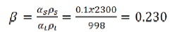
Particle loading of abrasive in AWSJ in the nozzle with different stokes number varies per unit area having different parameters to focus on the main spot at a time. Particles of abrasive plays greater impact on section interactions at the outline boundary because the mass density quantitative relation is explained by the relation of a particle with the carrier phase. The particulate loading for Garnet abrasive is,
The degree of interaction between the drag and turbulence phenomenon will influence the particulate fluid carrier and also get influenced by mean momentum and turbulence reduction. This type of drawback is noticed at all points of models also at multiple points, which is further corrected by the Eulerian point model.
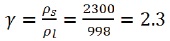
For Garnet abrasive,
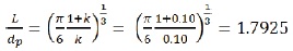
The average distance between the each particles of the particulate phase when particle size dp = 63 μm is,

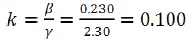
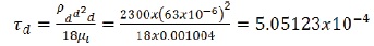
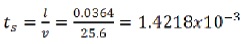
The best multi phase model can be taken by opting the precise value of stokes number. The Stokes number is defined as the ratio of the particle response time to the system response time and is calculated.
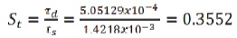
We will choose any 1 out of this 3 multiphase model, i.e., the volume of the fluid model, mixture model or Eulerian multiphase model, if stokes number comes one then the particle will follow the fluid flow multiphase model. As from formula and calculation, we can easily calculate the particulate loading coupling between the two intermediate phases. Hence by using the Eulerian multiphase model, the most accurate result are obtained at high cost. ANSYS FLUENT solver comprises of Eulerian multiphase model. This Fluent solves a single pressure of all the phases and also momentum and continuity equation for each phase. The granular temperature, solid-phase shear and viscosity are obtained by the study of a particle moving randomly and colliding with each other. Take the collision effect as inelastic in all the granular phase. Different variables like stresses, viscosity and pressure of the solid phase are determined by the severity of the particulate velocity fluctuation.
For continuous incompressible flow, control equations for mass and momentum conservation are solved. An algorithm for phase couples is simply developed for coupling between velocity and pressure. For turbulence flow, Realizable k-€ turbulence model is used. The governing partial differential equations, for mass and momentum conservations, are as stated.
Continuity Equation:
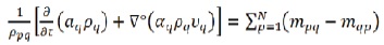
Where, p, q = phases, αq = volume fraction of the secondary phase, ρpq = density of suspended mixture (kg/m3), v= velocity, m= mass flow rate, N= lift force. Fluid-solid Momentum Equation:
The conservation of momentum equation for the solid phase is stated as,
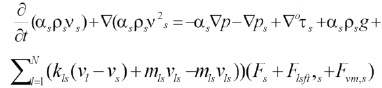
where αs =vol. fraction of solid phase, Fvm,s =virtual mass force of solid phase, ρs = density of the solid phase, K= momentum exchange coefficient, vs =velocity of the solid phase, τs= particle response time, l= length of flow domain (mm), Fs =external body force, Flift =lift force of solid phase, m = mass flow rate.
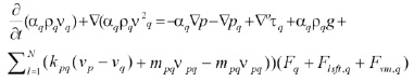
The conservation of momentum equation for the fluid phase is as follows.
Particle erosion and accretion rates can be monitored at wall boundaries. The erosion rate is defined by Brown (2002).
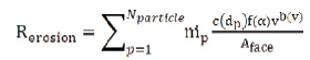
where,
c(d) = function of particle diameter
α = impact angle of the particle path with the wall face
v = relative particle velocity
b(v) = function of relative velocity
Aface = Area of the cell face at the wall
Defaults values are c = 1.8×10⁻⁹, f = 1 and b = 0.
The tangential force per unit area exerted by the flowing fluid on the surface of the wall of the conduit tube is given as,
where,
τd= shear stress
μ = dynamic viscosity
du = change in velocity
dr = change in radius of pipe/tube
To obtain the velocity and pressure fields for each control, volume conservation equation is solved. Curve convergence has been deviated when dependent fluid variable residual goes down i.e., below 0.00001 at the grid points. This computation of model will be done by using GAMBIT 2.3.30 software as per help document which is a commercially available pre-processor routine. Meshing is done by selecting a grid cell of suitable size. A boundary level meshing is done to observe and extract high-velocity gradients near the boundary wall. Grid independence test is performed to check the quality of mesh for solution convergence as shown in Figure 2. As negligible variation is observed in axial velocity distribution between mesh geometries of 21200, 25440 and 29690 control volumes. Hence mesh geometry of 30000 control volume has been adopted to obtain higher accuracy in solution. According to this condition, an axisymmetric model is constructed. Figure 3 and Figure 4 shows the computational domain as per Deepak et al. (2012).
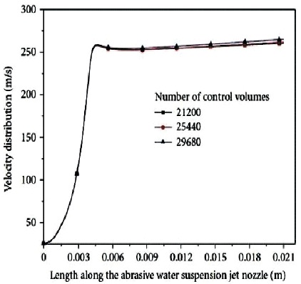
Figure 2. Result of Grid Independence Test for the AWSJ Nozzle
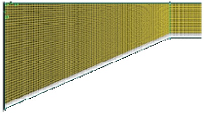
Figure 3. A Portion of Meshed Domain Near the Critical Section of AWSJ Nozzle
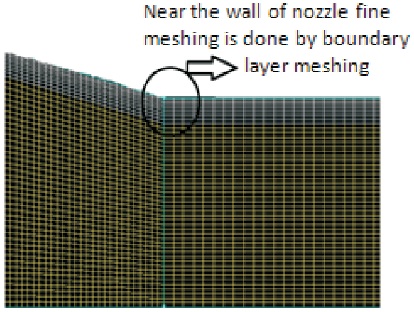
Figure 4. A Meshed Domains Near the Wall of the Nozzle
Suitable boundary conditions are imposed on the computational domain of nozzle of AWSJ machining as per the physics of the problem. Pressure inlet is opted and enters the nozzle at specified operating pressure. Velocity is assumed to be uniform throughout the section. Gauge pressure at the exit of the nozzle is zero so that the computational will be done through relative pressure difference across the grid volumes for the entire nozzle. Wall boundary condition as inlet and outlet at escape and wall discrete phase model boundary condition is a trap. In viscous flow models, the velocity component at the wall surface is set zero so that no chance of slip and impermeability conditions exist on the wall boundary. The problem is solved by computation domain as axisymmetric using constrained boundary condition for the same i.e., the values of fluid properties are set to zero across the axis line. Computational fluid dynamics simulation in the present numerical suspended liquid is treated as primary phase and abrasive is treated as a secondary phase.
The present model is benchmarked against the numerical work according to Deepak et al. (2012). The graph of the velocity distribution of one of the phases (liquid phase) has been calibrated in the present work as shown in Figure 6 with that of the work cited in the literature according to Deepak et al., (2012) as shown in Figure 5.
Figure 5 and Figure 6 both show that velocity first increases along the nozzle length, afterwards it becomes constant. It is clear that the present model shows a similar result as per the benchmarked model with respect to the velocity distribution.
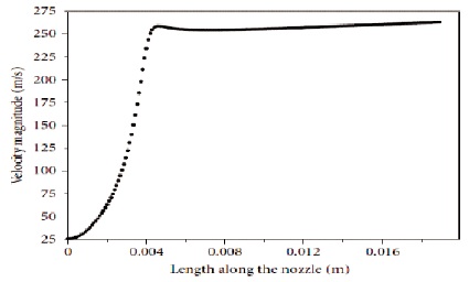
Figure 5. The Velocity Distribution Along the Length of the Single Step Nozzle (Deepak et al., 2012)
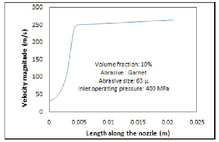
Figure 6. The Velocity Distribution Along the Length of the Single Step Nozzle for Present Model
Table 1 shows the tested parameters and their values. The inlet operating pressure 40 bar and volume fraction of abrasive is 10%. For geometrical analysis Garnet abrasive is taken with abrasive size of 63 μm.
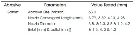
Table 1. Test Parameters and Values
Skin friction coefficient increases with increase in inlet diameter of the nozzle, as increase in diameter increases impact angle which further increases the abrasive velocity. This causes more shear stress and hence more skin friction coefficient. The data plot showing the variation of skin friction coefficient at the wall of nozzle for inlet diameter 3.8 mm and outlet diameter 1.3 mm is shown in Figure 7. The variation of skin friction coefficient at the wall of nozzle for inlet diameter 4.2 mm and outlet diameter 1.3 mm is shown in Figure 8.
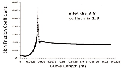
Figure 7. Variation of Skin Friction Coefficient at the Wall of Nozzle for Inlet Diameter 3.8 mm and Outlet Diameter 1.3 mm
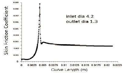
Figure 8. Variation of Skin Friction Coefficient at the Wall of Nozzle for Inlet Diameter 4.2 mm and Outlet Diameter 1.3 mm
Wall shear stress is inversely proportional to the diameter of inlet nozzle. Figure 9 and 10 shows the variation of wall shear stress for inlet diameter 3.8 mm and 4.2 mm respectively with an outlet diameter of 1.3 mm. From the figure we can infer that wall shear stress decreases with an increase in nozzle inlet diameter. As diameter decreases, lengths 3.79 mm, 3.89 mm, 4.13 mm and 4.25 mm are shown in Figure 11, 12, 13 and 14 respectively. It shows that with increase in nozzle convergent length, there is a slight decrease in skin friction coefficient.In the same way energy loss in pipe increases with an increase in pipe length as per Bernoulli law. Figure 15, 16, 17 and 18 shows the effect of wall shear stress for nozzle convergent lengths 3.79 mm, 3.89 mm, 4.13 mm and 4.25 mm respectively. There is a decrease in wall shear stress with increase in nozzle convergence length.
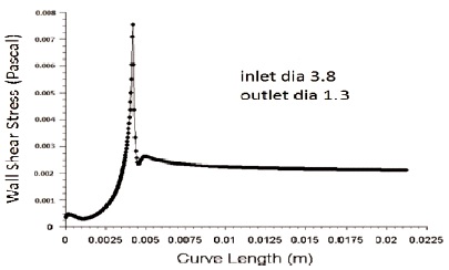
Figure 9. Variation of Wall Shear Stress for Inlet Diameter 3.8 mm and Outlet Diameter 1.3 mm
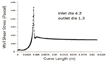
Figure 10. Variation of Wall Shear Stress for Inlet Diameter 4.2 mm and Outlet Diameter 1.3 mm
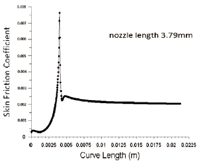
Figure 11. Variation of Skin Friction Coefficient for Nozzle Convergent Length 3.79 mm
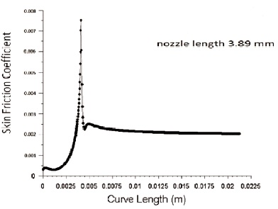
Figure 12. Variation of Skin Friction Coefficient for Nozzle Convergent Length 3.89 mm
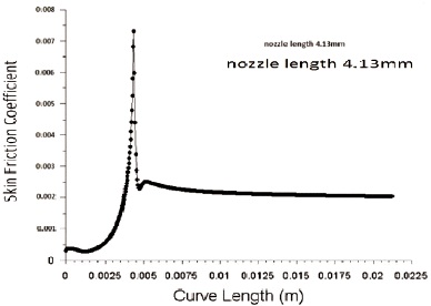
Figure 13. Variation of Skin Friction Coefficient for Nozzle Convergent Length 4.13 mm
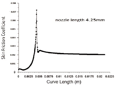
Figure 14. Variation of Skin Friction Coefficient for Nozzle Convergent Length 4.25 mm
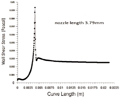
Figure 15. Variation of Wall Shear Stress for Nozzle Convergent Length 3.79 mm
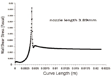
Figure 16. Variation of Wall Shear Stress for Nozzle Convergent Length 3.89 mm
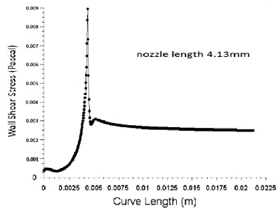
Figure 17. Variation of Wall Shear Stress for Nozzle Convergent Length 4.13 mm
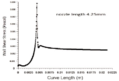
Figure 18. Variation of Wall Shear Stress for Nozzle Convergent Length 4.25 mm
Figure 19 and 20 shows the effect of skin friction coefficient for nozzle outlet diameter of 1.2 mm and 1.3 mm respectively for the inlet diameter of 4.2 mm. As the outlet diameter decreases, the skin friction coefficient also decreases.
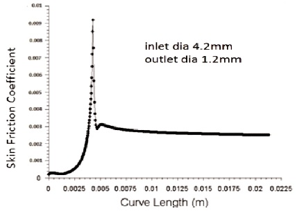
Figure 19. Variation of Skin Friction Coefficient for Inlet Diameter 4.2mm and Outlet Diameter 1.2 mm
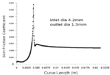
Figure 20. Variation of Skin Friction Coefficient for Inlet Diameter 4.2mm and Outlet Diameter 1.3mm
Figure 21 and 22 shows the variation in wall shear stress for nozzle outlet diameter of 1.2 mm and 1.3 mm respectively for the inlet diameter of 4.2 mm. As the outlet diameter increases, the wall shear stress decreases since wall shear stress is inversely proportional to exit diameter.The velocity of flow decreases with increase in outlet diameter and increase in velocity contributes to high skin friction coefficient at the nozzle wall.
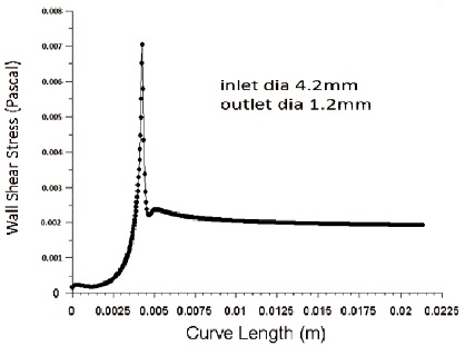
Figure 21. Variation of Wall Shear Stress for Inlet Diameter 4.2mm and Outlet Diameter 1.2mm
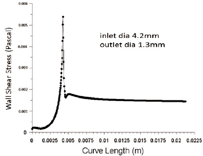
Figure 22. Variation of Wall Shear Stress for Inlet Diameter 4.2 mm and Outlet Diameter 1.3 mm
In the present research work, analysis is done on skin friction coefficient and wall shear stress by varying geometrical boundaries of a single-step nozzle. The wall shear stress and skin friction coefficient has been analyzed using ANSYS Fluent 6.2.2 software and designed by GAMBIT 2.2.30 software. Meshing and after mesh check is done for 2D asymmetric model. Enhanced wall treatment for realizable k-epsilon model in turbulent flow is done under control solutions. By using DPM analysis, nozzle wear during AWSJ machining is easily analyzed for better results at low cost. Higher the pressure of abrasive particle and water may cause sever wall shear due to wear and hence more wall shear stress. Also increased shear increases friction in the fluid flow, increasing the skin friction coefficient.
Following results are obtained from CFD Fluent simulation:
It is observed that higher the skin friction coefficient and wall shear stress induces higher wear of the wall. It is concluded from CFD analysis that nozzle geometry affects the wear rate and efficiency of AWSJ machining process.
The result obtained by CFD simulation provided good result and also useful for further studies on water suspension jet process.