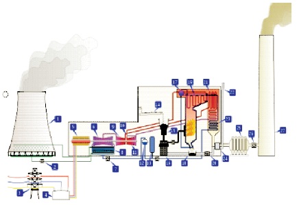
Figure 1. Thermal Power Plant Outline
A thermal power plant works on Rankine cycle. In this paper a case study of thermodynamic analysis of Rankine cycle has been chosen to enhance the efficiency of the existing thermal power plant in a steel industry. The practical Rankine cycle efficiency has been analyzed based on the existing value, and theoretical investigation for the improvement of the existing efficiency. A numerical calculation approach is used for improvement of the efficiency by considering the different improvement methods such as reheating, combination of reheating and regeneration of the cycle and other factors, based on the obtained results. From the calculation, suitable improvement method can be adopted in the thermal power plant for better efficiency.
Power plant plays an important role for the continuous working of a steel industry. The Thermal power plant in a steel industry has 5 boilers each generating 330 tph steam at 101 atm and 5400 oC. The boilers are capable of firing combination of fuels namely coal, coke oven gas, blast furnace gas and oil. Normally 4 boilers are kept in full load operation to produce 247.5 MW of power, and supply steam to 2 turbo blowers. The outlet flue gas passes through electrostatic precipitators to control air pollution. The fly ash and bottom ash generated are pumped in slurry form to ash pond through ground pipelines. The clarified water is recirculated back to the ash system.
The high pressure steam is produced in the boilers by burning fuel in the furnace. The high pressure steam is expanded in the turbine that causes the turbine to rotate the prime rotor coupled with the generator or the alternator and generates power. The steam from the turbine is condensed in the condenser and re-circulated back to the steam generator (boiler). The outline model of a thermal power plant is shown in Figure 1.
Figure 1. Thermal Power Plant Outline
Different units of the thermal power plant are:
Rankine cycle is the theoretical cycle on which the steam turbine works. The common working fluid is water. It is a closed cycle that enables the working fluid to be used again and again. Water is usually the fluid of choice due to its favourable properties, such as non-toxic and nonreactive chemistry, abundance, and low cost, as well as its thermodynamic properties (Roy, 2015).
The cycle consists of 4 processes as shown in Figure 2.
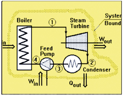
Figure 2. Rankine Cycle
The thermal efficiency (ηth) is a dimensionless performance th measure of a thermal device such as an internal combustion engine, a boiler, or a furnace, for example. The input, Qth to the device is heat, or the heat-content of a fuel in that is consumed. The desired output is mechanical work, Wout , or heat, Qin , or possibly both. Because the input heat out out normally has a real financial cost, a memorable, generic definition of thermal efficiency is,

From the first and second law of thermodynamics, the output cannot exceed the input, so 0£ h£1.0. When th expressed as a percentage, the thermal efficiency must be between 0% and 100%. Due to inefficiencies such as friction, heat loss, and other factors, thermal efficiencies are typically much less than 100%.
The Thermal Power Plant in is equipped with 5 units of boilers. Normally 4 boilers are in running conditions at full load and one is kept idle for emergency cases.
Table 1 indicates the boiler design data. The salient design data of the boilers are,
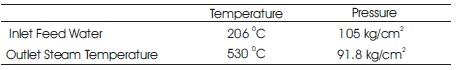
Table 1. Boiler Data
Boiler Capacity - 330 tph
Fuels fired - Pulverized coal, BFG, COG, HSD, HFO
SH steam pressure - 100 kg/cm2
SH steam temperature - 540 oC
Feed water temperature - 170 oC
It is defined as the ratio of heat utilized in generation of steam to the heat supplied by the fuel in the same period (Roy, 2015; Ameri et al., 2009).
It can be calculated in two methods:
Here we have calculated the efficiency of boiler by direct method.
Direct method:
The boiler efficiency can be obtained by calculating the output of the boiler (steam) and input of the boiler (water + coal + blast furnace gas (BFG) + coke oven gas (COG)) which can be expressed by
ηboiler = (Output/Input) ×100
Flow rate of steam (m) = 312.7 TPH
Output = Heat absorbed by working fluid
= Steam Enthalpy at boiler outlet – Water Enthalpy at boiler inlet
= 823.6 kcal/kg – 206.3 kcal/kg
= 617.3 kcal/kg
Heat generated (Output) by water
= m× (617.3) kcal/kg
=312700 × 617.3 kcal/kg
= 192939027 kcal/h
The heat input to the boiler is supplied by coal, blast furnace gas and coke oven gas. Hence the boiler is a multi fuel boiler. The consumption of each of the fuel may vary depending upon their availability. The fuel consumptions details are shown in Table 2.
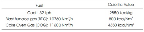
Table 2. Fuel Consumption
Heat input by coal = 32000 kg/h × 28500 kcal/kg
= 91200000 kcal/h
Heat input by BFG = 107670 Nm3/h × 800 kcal/Nm3
= 86136000 kcal/h
Heat input by COG = 11600 Nm3/h × 4350 kcal/Nm3
= 50460000 kcal/h
Total heat input = 228096000 kcal/h
ηboiler = Heat generated (output) by water/Total heat input
= 192939027/228096000
= 84.5%
Simple Rankine cycle in this thermal power plant,
ηRankine = Wnet /Q1 = (h1 – h2) / (h1 – ht4) (Rajput, 2015)
h1 = Enthalpy of superheated steam at exit of boiler (at 530 0C and 90 kg/cm2 )
= 3459 kJ/kg
h2 = Enthalpy of saturated steam at the end of expansion in turbine (at 54 0C)
= 2600 kJ/kg
hf4 = Enthalpy of wet steam at which feed water is fed into boiler (at 170 0C)
= 722 kJ/Kg
ηRankine = (h1 – h2)/( h1 – h14 )
= (3459 kJ/kg -2600 kJ/kg)/(3459 kJ/kg -722 kJ/kg)
= (859 kJ/kg)/ (2737 kJ/kg)
= 31%
Thermal efficiency of thermal power plant with assumed simple Rankine cycle is 31%.
The thermal efficiency of the Rankine cycle can be improved by the following methods (Boonnasa & Namprakai, 2008).
Let 1 kg of steam enters the turbine. Let m1 , m2 , m3 , m4 , be the mass of steam that is bled at 4 intermediate stages from beginning of high pressure expansion to end of low pressure expansion in the turbine into the heaters (HPH4, HPH3, LPH2,LPH1) respectively.
(Note: HPH – High Pressure Heater, LPH – Low Pressure Heater)
From the diagram obtained from the control room the corresponding temperatures and pressures at the point of bleeding have been noted as shown in Table 3.
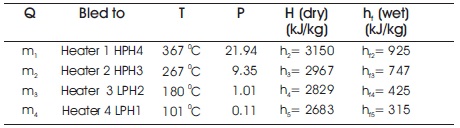
Table 3. Steam Tables Data Book Values (Jain, 2018)
The following values are taken from the control room of the power plant based on that the calculations are done (Murugan & Subbarao, 2008)
At the entrance of the turbine, at temperature 530 0C and 90 kg/cm2 ;
h1 = 3459 kJ/kg ,
hf1 =1352 kJ/kg
At the exit of the turbine at temperature 54 0C and 0.86 2 kg/cm2 ;
h6 = 2600 kJ/kg,
hf6 = 225 kJ/kg
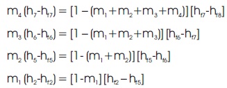
Applying energy balance equations for each of the heaters (Rajput, 2015), we get,
For heater 4:
m4 (h5 –hf5)=[1-(m1 +m2 +m3 +m4)](hf5 –hf6)
For heater 3:
m3 (h4 –hf4 )=[1-(m1 +m2 +m3)](hf4 –hf5 )
For heater 2:
m2 (h3 –hf3 )=[1-(m1 +m2 )](hf3 –hf4 )
For heater 1:
m1 (h2 – hf2 ) = [1- m1 ] ( hf2 – hf3 )
Substituting the enthalpy values in the above energy balance equations, we get
m1 (h2 – hf2 ) = [1- m1 ] (hf2 – hf3 )
m1 (3150 – 925) = (1- m1) (925 – 747.6)
m1 (2225) = (1- m1) (177.4)
13.5m1 =1 kg
m1 = 0.0738 kg
m2 ( h3 – hf3 ) = [(1- ( m1 + m2 )] (hf3– hf4)
m2 (2976- 747) = [1- 0.0738 – m2] (747 -425)
m2 (2229) = (0.926-m2 ) (322)
m2 = 0.1169 kg
m3 (h4 – hf4) = [1- (m1 + m2 + m3)] (hf4 – hf5)
m3 (2829 – 425) = [1 – 0.0738 – 0.1169 –m3] (425 -315)
m3 (2404) = (0.809-m3) (110)
m3 = 0.035 kg
m4 (h5 – hf5 ) = [1- (m1 + m2 + m3 +m4 )] (hf5 – hf6 )
m4 (2683 -315) = [1- 0.0738 – 0.1169 – 0.035 – m4) (315- 225)
m4 (2368) = (0.77-m4) (90)
m4 = 0.0283 kg
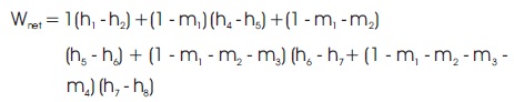
Net Work done according to (Rajput, 2015), can be calculated as
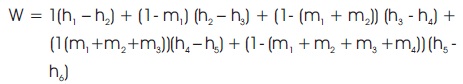
= 1 (3459 -3150) + (1-0.0738) (3150 -2976) + (1 - 0.0738 - 0.1169) (2976 - 2829) +(1- 0.0738 - 0.1169 - 0.035)(2829 -2863) + (1 - 0.0738 - 0.1169 - 0.035 - 0.0283)(2683 -2368)
= 309+1610.15+128.96+113.04+254.99
= 965 kJ/kg
Heat Supplied per kg of steam = h1 – hf2
= 3459 – 925
= 2534 kJ/KG
= (965 kJ/Kg)/ (2534 kJ/Kg)
= 38%
The calculated thermal efficiency of plant working on regenerative cycle is 38%
Steam consumption with regenerative feed heating
= 3.73 kg/kWh
Steam Consumption without regenerative feed heating:
= 3.29 kg/kWh
Difference in steam consumption
= Steam consumption with feed heating – Steam consumption without feed heating.
= 3.73 kg/kWh – 3.29 kg/kWh
= 0.44 kg/kWh.
Quantity of steam passing through the last stage of a 60 MW turbine with regenerative feed heating
= 3.73 (1- m1 – m2 – m3 – m4)× 60000
= 3.73 (1-0.0738 -0.1169 –0.035-0.0283)× 60000
= 166954.8 kg/h
Same without regenerative arrangement
= 3.29 × 60000
= 197400 kg/h
Thermal efficiency with 'Reheating' (neglecting pump work),
Heat supplied = (h1 –hf4) + (h3-h2)
Heat rejected = h4 –hf4
Work done by the turbine= Heat supplied – Heat rejected
= (h1–hf4) + (h3 –h2) - (h4 –hf4)
= (h1 –h2 ) + (h3 –h4)
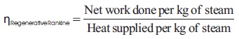
Thus, theoretical thermal efficiency of reheat cycle is
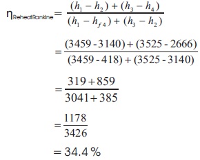
The calculated thermal efficiency of Rankine Cycle with reheating is 34.4%
m1, m2, m3, m4 are the masses of steam that has been fed to the heaters at various stages from 1 kg of steam that has entered at high pressure turbine.
Applying energy balance equations at each of the heater (Rajput, 2015), we have
Substituting the values of h from the steam table, To calculate m1 :
m1 (3150-925) = (1-m1) (925-756)
m1(2225) = (1-m1) (169)
14.16 m1 =1 kg
m1 = 0.070 kg
To calculate m2 :
m2 (h5 –hf5) = [(1 – (m1+m2)] [hf5 –hf6]
m2 (3364 – 756) = [(1 – (0.070 + m2) (756 -530)
m2 (2608) = (0.93-m2) (226)
m2 (11.53) = 0.93 – m2
12.53 m2 = 0.93 kg
m2 = 0.0742 kg.
To calculate m3 :
m3 (h6 –hf6) = [1 – (m1 +m2 +m3 )] (hf6 –hf7)
m3 (3100-530)= [1 – 0.070 – 0.074 – m3](530-450)
m3 (2570) = (0.856 – m3) (80)
m3 (33.12) = 0.856 kg
m3 = 0.025 kg
To calculate m4 :
m4 (h7 –hf7) = [1 – (m1 +m2 +m3 +m4)] (hf7 – hf8)
m4 (2945 -450) = [1 – 0.070 – 0.074 – 0.025 – m4] (450 – 389)
m4 (2495) = (0.83 – m4)
m4 (41.9) = 0.83 kg
m4 = 0.0198 kg.
Total work done per kg of steam supplied by the boiler (Rajput, 2015),
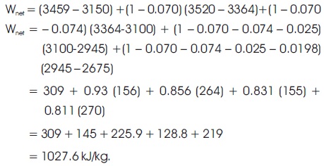
Qtotal = Heat supplied by the boiler per kg of steam + Heat total supplied in reheating process
Qtotal = Q1 + Q2
Q1 = Heat supplied by the boiler per kg of steam (Rajput, 2015)
Q1 = h1 – hf1
= 3459 kJ/kg – 1352 kJ/kg
= 2107 kJ/kg
Q2 = Heat supplied in reheating process (Rajput, 2015)
= (1 – m1) (h4 –h3)
= (1 – 0.070) (3520 – 3128)
= 0.93 * 392
= 364.56 kJ/kg
Total heat supplied = Qtotal = Q1 + Q2 (Rajput, 2015)
= 2107 kJ/kg + 364.56 kJ/kg
= 2471.56 kJ/kg
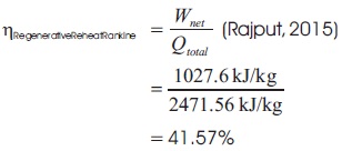
The calculated thermal efficiency of plant with combined regenerative reheat cycle is 41.57%
The thermal efficiencies of the steel industry power plant are calculated using different improvement methods and tabulated. Only mathematical equations are used to determine the thermal efficiency of the power plant as it is already established in the plant. The efficiency obtained from these calculations are compared with the practically obtained values. There is an error of 6.45% to 9.67% with the obtained results and this is a case study of how the actual power plant works and the methods to be considered for the improvement of the efficiency.
Table 4 shows the calculated values of efficiency. From the results it is noticed that the thermal efficiency can be increased by using different methods. The regenerative and reheat Rankine cycle shows higher efficiency of 41.2%. The efficiency obtained from numerical analysis shows variations when practically implemented as the entire power plant used in a steel industry produces 4 million tonne steel. This can be considered as a case study approach in exact operating conditions. This study will be useful for future researchers in modifying and simplifying power plant. Conditions and this study will be useful for the future to modify and simplify the power plant.
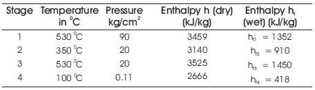
Table 4. Steam Table Values (Jain, 2018)
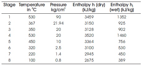
Table 5. Entalphy Values (Jain, 2018)
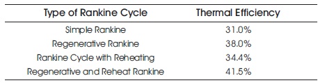
Table 6. Calculated Values of Efficiency
The practical investigations and analysis of the various important factors affecting the thermal power plant and thermal efficiency is discussed. The calculations and analysis explains that efficiency of a simple Rankine cycle is improved by using a intermediate reheat cycle and enabling the improvement of thermal conditions. The regeneration is vital to improve the efficiency as it uses the sensible heat of exhaust steam for the preheating of feed water. Inclusion of a feed water heater also introduces an additional pressure level into the Rankine cycle. The condenser vacuum and supply of condenser tube cooling water is another parameter. It is observed that though reheating improves thermal efficiency of Rankine Cycle by a considerable percentage, it is lower than efficiency of cycle with Regenerative method. A combined Reheat and Regenerative method results in a significant improvement in thermal efficiency.